manuals.online logo
Brands
  1. Home
  2. •
  3. Brands
  4. •
  5. Grumman American
  6. •
  7. Aircraft
  8. •
  9. Grumman American AA-5 1975 User manual

Grumman American AA-5 1975 User manual

Other Grumman American Aircraft manuals

Grumman American AA-5 User manual

Grumman American

Grumman American AA-5 User manual

Grumman American GA-7 COUGAR 1987 Owner's manual

Grumman American

Grumman American GA-7 COUGAR 1987 Owner's manual

Grumman American AG-5B Tiger Owner's manual

Grumman American

Grumman American AG-5B Tiger Owner's manual

Grumman American GA-7 COUGAR User manual

Grumman American

Grumman American GA-7 COUGAR User manual

Popular Aircraft manuals by other brands

Skywalk Mescal 4 instruction manual

Skywalk

Skywalk Mescal 4 instruction manual

Cessna U206G STATIONAIR Pilot operating handbook

Cessna

Cessna U206G STATIONAIR Pilot operating handbook

Cirrus SR22 Maintenance manual

Cirrus

Cirrus SR22 Maintenance manual

Schleicher ASK 21 Assembly & Disassembly

Schleicher

Schleicher ASK 21 Assembly & Disassembly

Cirrus SR20 Maintenance manual

Cirrus

Cirrus SR20 Maintenance manual

Skywalk Tequila 2 Manual/service

Skywalk

Skywalk Tequila 2 Manual/service

MAULE M-7-235B Airplane Flight Manual

MAULE

MAULE M-7-235B Airplane Flight Manual

Tecnam P92 Echo Super Maintenance manual

Tecnam

Tecnam P92 Echo Super Maintenance manual

Wills Wing HP II Owner's and service manual

Wills Wing

Wills Wing HP II Owner's and service manual

MAULE MX-7-180B Airplane Flight Manual

MAULE

MAULE MX-7-180B Airplane Flight Manual

Ozone ZENO 2 Pilot's manual

Ozone

Ozone ZENO 2 Pilot's manual

Boeing 737 Quick reference handbook

Boeing

Boeing 737 Quick reference handbook

MHD MHDFLY TINY GLIDER Z5630 Manual and using instructions

MHD

MHD MHDFLY TINY GLIDER Z5630 Manual and using instructions

Ozone Roadster Pilot's manual

Ozone

Ozone Roadster Pilot's manual

SpeedWing Mini SpeedWing EX Assembly instructions

SpeedWing

SpeedWing Mini SpeedWing EX Assembly instructions

Daher-Socata TBM 900 Pilot's information manual

Daher-Socata

Daher-Socata TBM 900 Pilot's information manual

Aircraft REIMS F152 Flight manual

Aircraft

Aircraft REIMS F152 Flight manual

Cessna 172 Skyhawk SERIES owner's manual

Cessna

Cessna 172 Skyhawk SERIES owner's manual

manuals.online logo
manuals.online logoBrands
  • About & Mission
  • Contact us
  • Privacy Policy
  • Terms and Conditions

Copyright 2025 Manuals.Online. All Rights Reserved.

I
GRUMMAN
AMERICAN
u
..
1 ' I
r
I
1975
Madel
AA-5~~~~~
and
Travele
r
0\IV
N E R ,S
MANUAL
CHECK LIST
MODEL
AA
-5 &
TRAVEL
ER
BEFORE
STARTI
NG
TAKE
-OFF
1.
PRE
FLI
G
HT
-
Fu
el. Oil, Prop, 1. Aux. Pump-
ON
Tire
s,
A1rc
ra
ft
Ge
ne
ra
l
Co
nd1t1on 2.
FULL
THROTTL
E
2. S
ea
ts and Be
lt
s- A DJUSTED 3.
Ra1
se
Nose-
55
to
60
MPH
3.
Br
akes- ON
CLIMB
4. Co
ntr
ols- FREE
5.
FUEL
-Fullest Tank ,.
FULL
THROTTLE
2. N
or
mal-100
MP
H
ST
ARTI
NG ENG
INE
CRUISE
1. Primer-AS
REQUIRED
1. Power-
2200
to 2700 RPM
2.
Mixture- RICH 2.
Aux
. Pump-
OFF
3.
Thrott
le- OPEN 1/8
IN
CH 3. L
ean
-AS REQUIRED
4.
Carb. Heat-
OFF
4. Fuel Quant
ity
-CHECK
5.
Master/Alt.
Switc
h- ON
6.
Au
x.
Pu
mp-
ON
(0.5
to
8 psi) BEFORE LA
NDING
Au
x.
Pu
m
p-O
FF 1. FU
EL-Fu
ll
est
Ta
nk
7. CL
EAR
PROP
2.
Aux.
P
ump
-ON
8.
Ignition
Switch- ON BOTH 3. Mi
xture
- AI
CH
9.
Starter- P
RESS
4. Carb. Heat-
AS
R
EQUIRED
10.
Oil
Pres
sure-CHECK 5. Fl
aps
-AS REQ
UI
RED
ENGINE RUNUP (Max. 120 MPH)
1. B
ra
ke
s-
ON 6.
Appr
oach-
75
MPH
2.
Thr
o
tt
le
-SET (1800 RPM)
AFTER
LANDIN
G
3. Engme lnst.- CHECK 1. Flaps-
UP
4. Magneto- CHECK
(1
75 R
PM
ea
.) 2. Carb. Heat-
OF
F
(Max. Di
ff
erence 50 RPM) 3. Aux. Pu
mp
-
OFF
5.
Ca
rb. Heat-CHECK
SHUT
DOWN
BEFORE T
AK
E-OFF
1.
Elec. EqUip
.-
OFF
1. Flap
s-
CHECK OPERA
TI
ON
2. Mi
xtur
e-
IDL
E CUT-OFF
2. Flaps- UP 3. Magnet
os-
a
FF
2.
Tnm
·- SET 4.
Ma
ster S
wit
ch-
OFF
3. Pnm
er
-
LOCKED
4. M1xture- RICH
5. Carb
Heat-OFF
6.
Contr
o
ls
-CHECK
7. Engine lnst.- CHECK
8. Flight
lnst
.
-SET
& C
HECK
9. Canop
y-
CH
EC
K
SERVICE REQUIREMENTS
FUEL:
Aviation grade . .
......
.
.....
80 /
87
minimum
grade
Capacity each
tank
....
......
...
....
....
19
ga
ll
ons
ENGINE OIL:
Aviation Grade
*R
eco
mmended
Grade Oil
Average
Ambient
Air
Above
600F
30°
to
90°F
0°
to
70°F
Below lOOF
Mineral Grade
SAE
50
SAE 40
SAE
30
SAE 20
Ashless Dispersant
SAE 40
or
SAE
50
SAE
40
SAE
40
or
SAE
30
SAE
30
O
il
Sump
Capacity
...................
8 U.S.
qu
arts
M
inimum
Saf
e
Quant
ity in S
ump
......
. . 2 U.S.
quarts
HYDR
AU
LI
C FLUID:
TIRE
I
NF
LATION:
Nose
Wh
ee
l
Main Wheels
MIL-H-56
06
21
PS
I
24 PSI
5.00
x 5 tire
6.00
x 6 tires
*
Refer
to
lat
est
revision
of
L
ycoming
Service Ins
truction
No.
1014.
Ful
ly illu
strated
Parts Catalogs
and
Service Manuals are
obtainab
le
through
authorized
Dealers
of
Grumman
American Aviation Corpora-
tion
or
from
the
Customer
Service
Department,
Clevel
and,
Oh
i
o.
Owner
____
______
____
________________________
_
Registr
at
ion No.
PERFORMANCE/S
PEC
I
FICATIONS
:
MODEL
AA
-5
GROSS
WE
IGHT .
.....
.
...........
.
........
2200
lbs.
SP
EED
: *
To
p Speed
at
Sea Level . . . . .
..
....
157 m.p.h.
Cruise,
75
% Power
at
85
00
ft
..
...
..
147 m.p.h.
Cruise,
65
% Power
at
8500 ft
..
.
....
136 m.p.h.
RANGE: Cruise,
75
% Power
at
8500
ft
. .
.......
638 mi.
37
Gallons, No Reserve . .
..........
.4.
3
hrs.
Cruise,
65
% Power
at
8500
ft
.........
674
mi.
37
Gallons, No Reserve
.............
5. 0
hrs
.
Opti
mum Range
at
1
0,000
ft
.........
680 m
i.
37
Ga
ll
ons, No Reserve
.............
5. 0 h
rs.
RATE
OF
CLIMB AT SEA
LEVEL
............
660
f.
p.m.
SERVICE CEILING
......
. . .
.......
.
.......
12,650
ft.
TAKE
OFF:
Gr
ound
Ro
ll
.....
.
...............
. .
880ft.
Total
Distance Over 50 ft.
Ob
stade
....
1600
ft.
LANDING:
Ground
Ro
ll
............
.
.....
.
....
380ft.
Total
Distance Over 50 ft.
Ob
stacle
....
1100
ft.
WING LOADING
........
..
...
.
....
..
.
..
15.7
lb./sq. ft.
POWER LOADING
.....................
.
14.7
lb./bhp.
BAGGAGE
....
.
..
.
.......
. .
..........
.
.....
120
lbs.
FUEL
CAPACI
TY:
TOTA
L. .
..
. .
....
.
..........
38
gal.
OIL CAPACITY:
TOTAL
.
..
..
....
. .
............
8 qts.
PROPELLER: McCAULEY
Fixed
Pitch
(Diamet
e
r)
....
73
in.
ENGINE: LYCOMING
Model 0-320-E2G
......
150
hp.
at
2700
r.p.m.
* Equi
pped
with
wheel fairings.
AAS-137-3-MUL-6000-9/74
This
manual
applicab
le
to
1975 m
ode
l.
Welcome Aboard!
Congr
at
ulations!
Your
AA-5
ha
s
been
designed
to
provide a
responsive, high
performance
four-place aircraft.
It
offers l
ow
hourly
cost
in flight
and
minimum
maintenance.
The
materials, tec
hniqu
es
and
design
innovations
which m
ade
the
AA-5 possible al
so
made
it
much stronger
and
more
hand
some
than
any
ot
her four-place airc
raf
t
in its class.
Metal-to-metal
bonding
eliminates
the
many
sou
rces
of
drag
and
st
ress
concent
r
at
ions
built
in
to
other
four-place aircraft,
and
leaves
the
aerodynamic
su
rf
aces s
mo
ot
h as glass.
Aluminum
h
oneyco
mb
co
mpl
ete
ly
su
rround
s the
cabin,
providing a lightweig
ht,
except
ionally
st
rong passenger
co
mp
a
rtm
ent
for
maximum
safety.
The
AA-5's
com
bina
tio
n
of
st
ren
gt
h,
performance,
agili
ty
and
economy
plus the rear
seat
conve
rtibility, make
it
an exce
ll
ent
passenger or utility aircr
aft
for
l
oca
l
or
cross-
country
flights.
Get
to
know
yo
ur
authorized
Grumman
Amer
ican Aviation Co
rp
-
oration
Dealer. He
can
provide
the
fast,
expe
rt service
that
will keep
your
AA-5 in excelle
nt
condition
for
many,
many
years. His factory-
trained
service
people
are
professionals.
9-1/
8"
PRINCIPAL
~
~
DIMENSIONS
II
II
. .
;]
.
[)
"-,
'
""
../
~
31' 6"
73"
MA
X.
i i
TABLE
OF
CONTENTS
Performance/Specifications
Section
I
Section
II
Section
III
Section
IV
Section
V
Section
VI
Section
VII
Warranty
Description
of
Systems
&
Structures
Check
List
&
Operating
Instructions
Operating
Procedures
Operating
Limitations
Performance
Charts
Emergency
Procedures
Care
of
the
Airplane
Service
Requirements
Check
List
Illustrations,
Charts
and
Graphs
Three
View
Fuel
System
Diagram
Electrical
System
Schematic
Walk-Around
Inspection
Instrument
Panel Diagram
Seating-Cargo
Arrangements
Loading
Graph
Sample
Loading
Problem
Center
of
Gravity
Envelope
Graph
Cargo
Belt
Configuration
Baggage
Strap
Buckling
Illustration
Take
Off
Data
Maximum
Rate-of-Climb
Data
Cruise &
Range
Performance
Landing
Data
Stall
Speeds
Airspeed
Correction
Table
Maximum
Glide
Chart
PAGE
inside
front
cover
1-1
2-1
3-1
4-1
5-1
6-1
7-1
7-4
inside
back
cover
back
cover
ii
1-4
1-6
2-1
3-2
4-3
4-4
4-5
4-6
4-7
4-7
5-2
5-3
5-4
5-5
5-5
5-5
5-6
i i i
SECTION
I
DESCRIPTION OF SYSTEMS & STRUCTURES
The
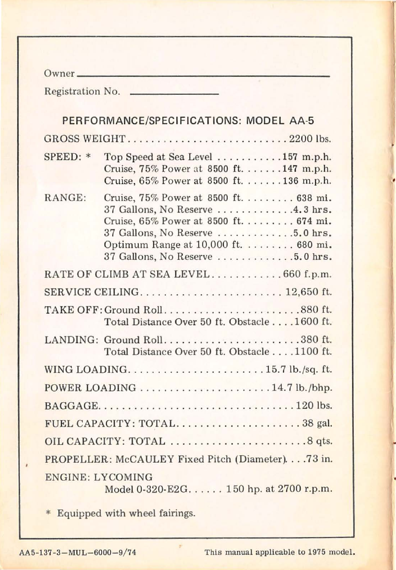
Model AA-5 is a four-place, all metal, low-wing monoplane.
It
is powered
by
a
150
horsepower Lycoming four-cylinder, horizontally
opposed engine with a fixed-pitch metal propeller.
Airframe
components
such as wings, fuselage
and
tail assemblies
employ high-strength adhesive bonding
of
aluminum
sheet
metal
to
ribs
and bulkheads.
The
cabin area is
constructed
primarily
of
bonded
aluminum
honeycomb
panel.
CABIN DESCRIPTION
1. CABIN DOME
LIGHT
A cabin
dome
light
is
provided for illuminating
the
seating area
and
baggage
compartment.
It
is controlled by a 3-position
rocker
switch which
is
located
on
the
fuselage side panel
to
the
left
of
the
pilot's
control
wheel. This location provides easy operation by
the
pilot
when in flight, and also convenient access from
the
outside
when entering
the
aircraft
at
night. The switch forward position
illuminates
the
front
cabin area,
the
center position
is
off,
and
the
aft
position illuminates
both
the
front
and rear cabin areas.
It
is
energized directly from
the
battery
regardless
of
the
master switch
position.
2. SEAT
AND
BELTS
Contoured
front
seats are individually adjustable fore
and
aft
using
the
adjustment
levers located
on
the
outboard
side
of
each seat. The
front
seat
backs fold forward for easy access
to
the
rear seat.
NOTE
Shoulder
belts are provided for
your
safety.
Be
sure to use them.
The
shoulder
belt
fastens
to
the
end
of
the
outboard
lap belt,
allowing
both
belts
to
be
fastened
or
removed in
one
operation.
Lap and shoulder belts may
be
neatly stowed
by
hanging them
on
the
side panel
supports
provided.
Lap belts should
be
adjusted
to
lie low on
the
hips,
without
any
slack. Shoulder belts should lie over
the
outer
shoulder
and
across
the
chest, with
just
enough slack
to
reach all controls comfortably.
3. CARGO
CONFIGURATION
The
rear
seat
and
seat
back may be folded forward
to
provide a
1-1
large cargo area. Both
front
seats should
be
in
the
full forward
position
to
swing
the
rear seat
bottom
up
and fold
it
forward.
NOTE
When
the
rear seat
bottom
is
folded
forward,
the
rear seat
back
must
be folded
down.
The rear
seat
shoulder harnesses
may
be
removed
and
used
to
secure
items in
the
cargo area when
the
rear seats are folded
down
in
the
cargo configuration. These harnesses
may
be
hooked
to
any
of
the
exposed
lap
belt
attachment
points as shown in
the
cargo
belt
diagram
in
Section 4.
A baggage door
is
provided
on
the left side
of
the fuselage for
access
to the baggage compartment. The baggage door latch
is
key
operated
from the outside and can be opened from the inside
by
a simple slide
handle.
Consult Section 4, Weight and Balance,
for
loading instructions
to
load
the
airplane with cargo.
4. INSTRUMENT PANEL
The
instrument
panel employs a
unique
"eyebrow"
design which
shields
the
windshield from panel reflections
during
night flights.
The eyebrow also houses
the
instrument
panel lights which are
controlled
by
a switch
rheostat
(ON-oFF
and
INTENSITY)
located
just
above
the
throttle.
Other
panel switches are also
the
rocker
type.
5. CONSOLE
The center console serves
as
a
front
seat
divider, provides storage
for
the
microphone, houses
the
microphone
jack,
the
flap switch,
flap position indicator,
trim
wheel,
trim
position indicator, ash
tray, cigarette lighter, fuel selector valve,
and
fuel gauges.
FLIGHT CONTROLS
The
control
surfaces are
operated
by a
combination
of
torque
tubes
and conventional cable systems.
The
elevator
trim
tabs are
located
on
the
elevator trailing edges and are anti-servo tabs. These trim
tabs
are
actuated
manually
by
the
trim wheel located
on
the
center
console.
Ground adjustable tabs on
the
rudder
and ailerons provide a simple
method
of
adjusting directional and lateral
trim.
Electrically
operated
flaps provide a full range
of
settings by means
of
a spring-loaded,
three
position switch.
The
flap
actuator
switch
is
held
down
until
the
flap position indicator shows
the
desired flap angle;
when released,
it
returns
to
neutral,
and
flap travel stops.
1-2
(Caution:
abruptly
releasing
the
switch may cause
it
to
snap
through
the
neutral
detent,
into
the
retract
position.)
To
retract
flaps, push
the
switch forward
and
release it;
the
flaps
retract
fully with
no
further
attention,
and
the
flap drive
motor
shuts
off
automatically.
ENGINE CONTROLS
The push-pull
throttle
control,
located in
the
lower
center
in-
strument
panel,
is
equipped with a friction lock
to
prevent creeping
(but
which can be overridden manually). The
mixture
control and
carburetor
heat
control,
to
the
right and left
of
the
throttle,
respectively,
are also
of
the
push-pull design.
FUEL SYSTEM
The
AA-5's fuel system (Figure 1) consists
of
two
tanks located
just
outboard
of
the
wing
root
fairing,
two
sump tanks (one in each
wing
root
fairing),independent fuel gauges and a fuel selector valve.
The
fuel tanks are vented and
equipped
with
two
main fuel lines in each
tank,
located
to
assure fuel supply in all normal flight attitudes.
The
flush
mounted
fuel
tank
vents are located in
the
bottom
of
the
out-
board wing panels,
just
forward
and
inboard from
the
wing tie downs.
A mechanical fuel
pump
mounted
on
the
engine transfers fuel from
the
tanks
to
carburetor.
An au.xiliary electric fuel
pump
supplements
the
engine-driven
pump.
Fuel pressure
is
indicated
on
a gauge in the engine
instrument
cluster, located
to
the
right
of
the
radio section
of
the
instrument
panel.
The
electric
pump
should be
turned
on if
the
engine-driven
pump
fails
as
noted
by a loss
of
fuel pressure. The electric fuel
pump
can also be
used
to
provide fuel pressure redundancy during low
altitude
operation,
such as during take-off and landing.
There are
four
fuel drains on
the
airplane. One
is
located in each
fuel
tank,
and
one
in each
sump
tank.
They can be reached
under
the
front
side
of
the
wing
at
the
wing
root
on
each side
of
the
airplane. A
drain
cup
is
provided (in
the
glove
box)
for draining fuel which should
be inspected for water
or
sediment
contamination.
HEATING
AND
VENTILATION
Cabin
heat
and
defrost
air
are
supplied
by
a
heat
exchanger on the
engine
exhaust
system.
The
supply
of
warm
air
for the
heater
and
de-
froster
is
controlled
by
the cabin
heater
control
on the
center
of the
instrument
panel.
Fresh air ventilation
is
provided by adjustable vents located
just
below
the
instrument
panel, with the air supply being
ducted
in from
inlets in
the
fuselage. Maximum ventilation can be
obtained
by sliding
1-3