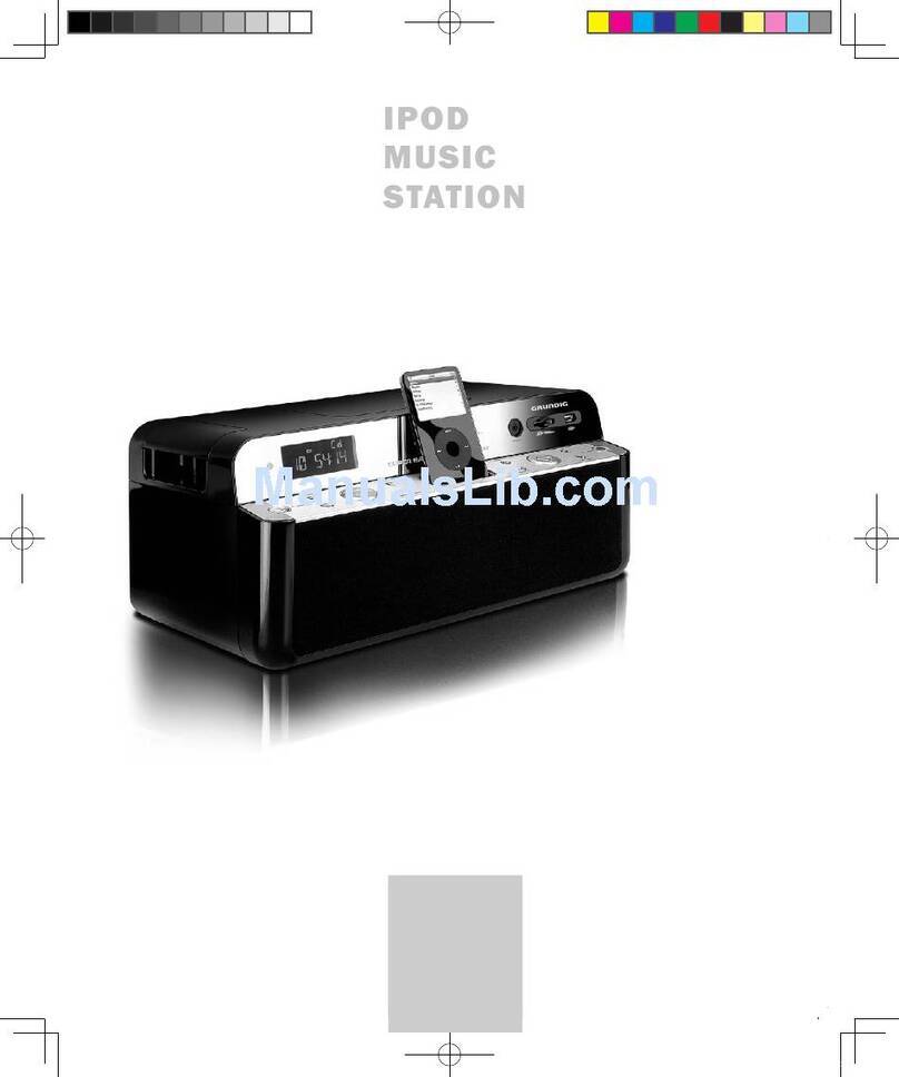
Grundig CDS2650IP User manual

The Gold Technical Support Line:1902 215 259
CDS2650IP
Music Station with Dual Dock
for iPod/iPhone
(Charges will apply at $2.95 per minute)

TABLE OF CONTENTS
Introduction
Australia.
Grundig Warranty: 1800 509 394
New Zealand
Grundig Warranty: 0800 450 259
1
Before We Begin ...................................................................................................1
Preparation for Use ................................................................................................2
Install / Replace Backup Battery .............................................................................3
Location of Controls & Indicators ............................................................................5
Remote Control ......................................................................................................7
Operating Instructions ............................................................................................8
Connecting External Devices..................................................................................8
Radio Operation ...................................................................................................11
Presetting Stations In The Tuner Memory .............................................................13
Alarm Setting .......................................................................................................15
iPod / iPhone Operation .......................................................................................18
Technical Specification ........................................................................................21
Warranty ................................................................................................................22
BEFORE WE BEGIN
Thank you for purchasing this audio product. This is your assurance of quality,
performance and value. Our engineers have included many useful and convenient
features in this product. Please be sure to read this Owner’s Manual completely to
make sure you are getting the maximum benefit from each feature.
This product was manufactured using the highest quality components and
standards of workmanship. It was tested by inspectors and found to be in perfect
working order before it left our factory. However, there is always the chance that
some problems may occur because of rough handling during shipment to the retail
store or to the final consumer. If you experience any problems with the operation of
this product, please refer to the instructions for obtaining services at the end of this
manual.
Once again, thanks for purchasing this audio product.
For future reference, record the serial number in the space provided.
Model No: CDS2650IP
Serial Number: __________________________________________________
Thank you for buying this Grundig product, which is designed to give you many years
of trouble-free service.
You may already be familiar with using a similar unit, but please take time to read
these instructions. They are designed to familiarise you with the unit’s many features
and to ensure you get the very best from your purchase.
Safety is important
Your safety and the safety of others is important.
Please therefore, ensure you read the “Safety Instructions” before you operate this
unit.
Warranty
In the unlikely event that your product fails to work properly, please call one of the
below free phone numbers to discuss the problem with one of our qualified service
engineers.

STEREO HEADPHONE JACK
Unpacking and Set Up
This system includes a stereo headphones jack on the rear panel of the main unit.
You may connect a set of stereo headphones(not included) to this jack for private
listening without disturbing others.
The main unit speakers are automatically shut off when headphones are connected
to the headphones jack. Make sure that the plug from your headphones is fully
inserted into the headphones jack. If the plug is not fully inserted the sound may be
intermittent, or you may only hear sound from one side of the headphones.
IMPORTANT: To prevent hearing damage always set the volume control to a low
level before you connect the headphones. Then connect the headphones and put
them on, very gradually increase the volume to a comfortable listening level.
23
Battery Installation
Battery
Compartment
The battery compartment for the lithium CR2032 Battery is located on the bottom
panel. To change the battery, remove the cover and insert the lithium CR2032
Battery in the respective compartment. Be sure that the battery is installed correctly
according to the marking in the battery compartment. If the battery is not installed
correctly the unit will not work.
After installing the battery replace the battery compartment cover and ensure this is
closed.
The lithium CR2032 Battery is used for maintaining the clock and timer. It will provide
back up power for the clock and timer for 6 months.
PREPARATION FOR USE
Remove the main unit, the AC adapter, all accessories and the six iPod®
adapter from the carton. Also remove all packing material from the main unit. We
recommend that you save the carton and packing material in the event that the
unit ever needs to be returned for service. Using the original carton and packing
material is the only way to protect your unit from damage during shipment.
Remove any descriptive labels or stickers from the top or front panels of the unit.
Do not remove any labels or stickers from the back or bottom panels.

5
4
Using The AC Adapter
Connect the small female plug of the AC Adapter to the DC Input Jack on the back
panel. Connect the housing of the AC Adapter to the 240V AC outlet.
When the adapter is connected to the unit the AC power source is selected
automatically, even if there are batteries in the battery compartment. Note: in order
to operate the unit on batteries the AC Adapter must be completely disconnected
from the DC Input Jack on the back panel.
NOTES:
normal.
Adapter while your hands are wet.
Protect Your Furniture
This model is equipped with non-skid rubber 'feet' to prevent the product from
moving when you operate the controls. These 'feet' are made from non-migrating
rubber material specially formulated to avoid leaving any marks or stains on your
furniture. However, certain types of oil based furniture polishes, wood preservatives
and / or cleaning sprays may cause the rubber 'feet' to soften and leave marks or a
rubber residue on the furniture. To prevent any damage to your furniture we strongly
recommend that you purchase small self-adhesive felt pads, available at hardware
stores and home improvement centers. You can apply these pads to the bottom of
the rubber 'feet' before you place the product on fine wooden furniture.
MWANT
1 2 3 4
5 6 7 8 9
10 11 12 13 14 15
16
17 18 19 20 21 22
1 . iPod Indicator
2 . Universal Dock for iPod
3 . Universal Dock for iPod/iPhone
4 . iPod/iPhone Indicator
5 . STANDBY Button
6 . VOLUME + / - Button
7 . MODE Button
8 . ALM 1 / PRESET - Button
9 . ALM 2 / PRESET + Button
10. SNOOZE/DIMMER Button
11. TIME SET / MEMORY Button
12. SLEEP Button
13. PLAY/PAUSE Button
14. TUNING/SKIP / Button
15. iPod SELECT Button
16. Display
17. FM AERIAL Wire
18. MW AERIAL Socket
19. AUX IN Jack
20. HEADPHONES Jack
21. DC IN Jack
22. Backup Battery Compartment(inside)
MWANT
LOCATION OF CONTROLS & INDICATORS

7
6
Low Battery Indicator
Alarm Indicator
Daylight
Savings Time
TIME AM / PM
Indicator
Wake To Indicator;
iPod,Radio,Buzzer.
Time/Alarm Display
SLEEP,
SNOOZE
Indicator
STEREO
Indicator
Left iPod Indicator
Right iPod Indicator
MW/FM Indicator
AUX/Radio Frequency/ Volume Level/
EQ/ DBBS Indicator
LCD DISPLAY
MW
1 . STANDBY Button
2 . MUTE Button
3 . VOLUME Button
4 . FM ST/MO Button
5 . DBBS Button
6 . SLEEP Button
7 . TIME SET / MEMORY Button
8 . PRESET MENU - Button
9 . MENU Button
10. TUNING/SKIP Button
BATTERY INSTALLATION
Insert (lithium CR 2032) into the battery compartment of the remote.
BATTERY REPLACEMENT
When the battery becomes too weak, the operating distance of the remote control
is greatly reduced. You should then replace the remote control battery.
NOTES:
To maintain the accuracy and long life of the transmitter, do not press two or
more buttons simultaneously.
If the remote control is not to be used for a long time, remove the battery to
prevent possible damage through a leaking battery.
USING THE REMOTE CONTROL CORRECTLY
Insert lithium CR 2032 battery into the remote control as shown below:
1
2
3
4
5
6
7
8
9
01
11
21
31
41
51
61
71
81
91
02
12
11. ENTER Button
12. iPod SELECT Button
13. PLAY/PAUSE Button
14. SNOOZE / DIMMER Button
15. VOLUME Button
16. EQ Button
17. ALM 2 Button
18. ALM 1 Button
19. PRESET MENU + Button
20. TUNING/SKIP Button
21. MODE Button
REMOTE CONTROL
SNOOZE /
DIMMER
PRESET MENU
VOLUMEMUTE
FM ST/MO DBBS EQ
SLEEP
MENU
ENTER
MODE
iPod SELECT
ALM 1 ALM 2
TIME SET
MEMORY
STANDBY
Point the remote control at the remote sensor.
The functions of the buttons on the remote control are the same as the
corresponding controls on the main unit.
When there is a strong ambient light source, the performance of the infrared
remote sensor may be degraded, causing unreliable operation.
The maximum effective distance for remote control operation is about 15 feet.

CONNECTING EXTERNAL DEVICES
89
OPERATING INSTRUCTIONS
General Controls
Most of the main functions of this system can be operated by the controls on the front
panel of the main unit, or by the buttons on the remote control handset. If a specific
function can only be operated by the remote handset, or by the front panel controls,
this will be clearly indicated in the instructions.
When operating this system with the remote control handset make sure that the IR
(Infrared) transmitter on the front of the remote handset is pointed at the remote
sensor on the front panel of the main unit.
The effective operating range of the remote control is approximately 15 feet. Please
note that bright sunlight or room lighting may interfere with the remote control
operation. If the remote is not operating properly try reducing the brightness of the
room or moving closer to the main unit. If this does not solve the problem, it may be
time to change the remote control battery.
AUXILIARY INPUT JACK
This system includes an AUX IN Jack to allow you to connect external audio
equipment and listen to the sound from the external equipment through the
speakers of this system.
To listen to the external audio source:
Connect the external audio equipment to AUX IN Jack
on the rear panel of the system as shown below.
Select the “AUX” using the MODE button.
plug
External audio source
Signal cord (not included)
MWANT
Setting The Clock
When the unit is connected to the AC outlet for the
first time “ AM12:00 ” flashes on the display.
Note!"#
main unit power is in STANDBY mode. Remember to set the correct time AM or PM.
1.)
Setting the DST(Daylight Savings Time)
1.) Press and hold the MODE button on the remote
control. The “DST” and “1” will appear on the display,
the time will advance one hour.
2.) Press the MODE button again and the “0” will appear
on the display. The clock will automatically return
to the current time.
Press and hold TIME SET / MEMORY button. The
hour digit will flash. Press TUNING / SKIP or
button to set the correct hours and then press TIME
SET / MEMORY to confirm, then the minute digit will
flash. Press TUNING / SKIP or to set correct
minutes. Press TIME SET / MEMORY button to
confirm.

Volume Controls
To increase or decrease the system volume press the VOLUME or VOLUME
button on the remote control or volume control on the top panel. The Volume
Level Indicator will appear on the display when you
change the volume level. The level indicator ranges from
“00” (minimum) to “30” (maximum).
The system remembers the volume level when the power is switched ‘Off’ and
automatically returns to the same level when the power is switched ‘On’ again.
EQ(Electronic Preset Equalizer)
The preset equalizer allows you to adjust the sound
characteristic for the most popular types of music.
Press the EQ button on the remote control to
cycle through the
following equalization modes:
The appropriate EQ indicator briefly appears in the display to
confirm your selection.
The system remembers the EQ setting when the power is switched ‘Off’ and returns
to the same setting when the power is switched ‘On’ again.
DBBS (Dynamic Bass Boost) Control
Press the DBBS button on the remote control to increase the bass response.
Press
again to cancel the Bass Boost function.
MUTE Button (On Remote Control Only)
Press the MUTE button on the remote control to shut off the
speakers temporarily, for example, to answer the telephone.
The sound stops and the “VOLUME” indicator flashes
for 3 minutes on the display.
Press the MUTE button again to cancel the mute function and restore the sound.
The mute function will also be cancelled automatically by pressing the VOLUME
or button.
EQ1(FLAT) EQ2(CLASSIC) EQ3(ROCK) EQ4(POP) EQ5(JAZZ)
11
1.) Press the STANDBY button to turn the system ‘On’.
The default Mode for this system is the iPod function.
The iPod®indicator will flash above the time display.
2.) Press the MODE button repeatedly to select the MW or FM Tuner function.
3.) Tune to the desired station as follows:
Manual Tuning
Repeatedly press the TUNING/SKIP or buttons on the remote handset or
touch the SKIP/TUNING or button on the unit until the display shows the
frequency of the desired station.
Press and hold the TUNING/SKIP or buttons until the frequency starts to
change rapidly then release the buttons. The Tuner will search up or down the
band for the next strong signal and stop on that station. Repeat this procedure
until the Tuner stops at the desired station.
4.) If you tuned to an FM Stereo station the ST indicator
will appear in the display. If the FM Stereo reception
is noisy or weak, press the FM ST/MO button on the
remote control to select the FM Mono mode.
5.) After listening press the STANDBY button to return the system to the Standby
(Off) mode.
10
RADIO OPERATION
Hits For Better Reception
FM: The FM lead wire antenna on the back panel should be extended to its full
length. You may also have to vary the direction of this antenna until you find
the position that provides the best reception.
MW: Insert the wire of loop aerial into the MW AERIAL connector on the unit.
Adjust the position of the loop aerial until you find the position that provides
the best reception for your favorite MW stations
.
FM ANT
MW ANT
13
12
Up to 40 radio stations(20 FM / 20 MW) can be stored in the Tuner Memory for
easy recall at any time.
Using either the manual or automatic tuning method described above, tune to the
first station to be stored (Example below uses FM 103.5 MHz on FM band) and then:
1.) Press and hold the TIME SET / MEMORY button on
the remote control. The memory location station
“FM103.5 MHz” will appear on the display.
Press the TIME SET / MEMORY button again to stop
flash and the channel number “P-01”.
2.) Press the PRESET MENU + or - button to select the
desired preset memory number. Example “P-03”.
Press the TIME SET / MEMORY button again and the
“P-03” stops flashing confirming that the station has
been stored in preset channel number “P-03”. After the
display shows “FM 103.5 MHz”.
3.) Tune to the next station you wish to store and repeat steps 1 to 2 until you have
stored up to 40 stations (20 FM / 20 MW) in the Tuner Memory.
Tuning into a Preset Station
Press the PRESET MENU + or - button repeatedly until
the desired preset number and frequency is shown on the
display(Example: FM107.5 MHz).
FM ANT
To connect the MW loop antenna
Presetting Stations In The Tuner Memory

Sleep Timer
This system includes a Programmable Sleep Timer that allows you to fall asleep to
between 10 and 120 minutes of music and then turns the unit to standby automatically.
To operate the Sleep Timer:
1.) Turn the system ‘On’ and operate the Tuner function as usual.
2.) Press the SLEEP button on the remote control or theSLEEP control on the
top panel.
3.) The display will show “SLEEP 120”indicating that the
sleep timer will shut the power off after 120 minutes.
Repeatedly press the SLEEP button to decrease the amount of sleep timer operation.
4.) After a few seconds the Sleep Time display disappears
and the normal Tuner display returns, but the small
SLEEP indicator remains on the display. When the
Sleep Timer counts down to“00”, the unit turns to
standby automatically.
Notes:
by pressing the STANDBY button at any time.
SETTING THE ALARM
Note!"#
main unit power is in STANDBY mode. Remember to set the correct time AM or PM.
1.) Press and hold the ALM1 button to enter the Alarm
Time setting mode. The alarm indicator appears and
the hour digits begin blinking in the display.
2.) Press the TUNING/SKIP or button repeatedly
until the display shows the desired wake-up hour.
3.) Press the ALM1 button to confirm. Then the
minute digits will begin blinking.
4.) Press TUNING/SKIP or button repeatedly until
the display shows the desired wake-up minute.
5.) Press the ALM1 to enter the alarm mode setting,
Press the TUNING/SKIP or button to select
the desired alarm mode, iPod®/Radio /Buzzer and
press ALM1 to confirm.
6.)
Press the ALM1 to enter the alarm volume setting. Press the
TUNING/SKIP
or button to select the desired volume.
7.) Press the ALM1 again to save and exit the alarm time setting mode.
8.)
15
14
ALARM SETTING
When the actual time matches the alarm time the system will turn on to the
Buzzer, Radio or iPod
®
alarm automatically. The Buzzer, Radio or iPod
®
will
continue to operate for one hour and then shut off and reset itself for the same
time on the following day. To stop the alarm sooner, press the ALM1 button
and press the TUNING/SKIP or button to deactivate the alarm. The ALM1
indicator on the front panel will turn ‘Off’.

SETTING THE SNOOZE / DIMMER
1.
2.
16
Main unit, remote
Remote
Control Location Function
MENU
iPod SELECT
Main unit, remote
Main unit, remote Press once to select track
Press to play, press again to pause
iPod MENU function
iPod SELECT function
MODE
17
Dock Adapter Compatibility
iPhone
3G iPhone
A B C D E F
8GB
8GB
16GB
16GB
160GB
Playing Music From Your iPod
Press PLAY on the iPod, main unit or remote. The music playback will start.
You can control all of the iPod’s functions including menu navigation from the remote
control. You can select tracks, play, pause and stop music from the main unit.
When the alarm is active, press the SNOOZE / DIMMER button to silence the
alarm for nine minutes. After the nine minutes snooze interval, the alarm will be
active again. The snooze timer starts counting down after the
SNOOZE / DIM-
MER button is released. Snooze can be used repeatedly within the one hour
active alarm interval.
During normal operation, press the SNOOZE / DIMMER button to control the
brightness of the LCD display.
9.) The ALM2 settings is the same as ALM1.
Notes:
Alarm volume setting can be selected only at iPod and Radio mode.
If you selected the wake to iPod mode but there is no iPod docked at the wake
up time, the system will default to Buzzer mode automatically. If you selected
the wake to Radio mode, the unit will sound to the latest FM/MW station you
listened before turning off the unit.

When connecting an iPod to this iPod Dock, please ensure that the
correct adapter plate is used. FAILURE TO DO SO MAY RESULT IN
DAMAGE TO THE iPod.
NOTE: The adapter for iPod nano is already installed in the dock.
To place a dock adapter:
1. Refer to the compatibility table below and select the correct
dock adapter for the iPod.
2. Place the proper adapter into the dock and press it
into position. The adapter will only go in one way.
The iPod dock connector should fit through the
opening in the bottom of the adapter.
3. Carefully align and then gently insert the iPod into
the dock. (The iPod must not be in a case or “SKIN”)
4. To remove/replace a dock adapter, first remove the
iPod, then grip the adapter and pull gently upwards.
Choosing The Correct Adapter
Listening to your iPod / iPhone
1. Insert the iPod as described above.
2. With the unit turned on, press the MODE button
repeatedly until "iPod®" is shown in the display.
3. Press the Play / Pause button on the Micro System to commence, control
playback and pause.
4. iPod / iPhone operate same as an iPod.
5. I
nsert the iPod and the iPhone at the same time. The system will choose the
“iPhone” previously playing.
6. Press the iPod SELECT button to select the iPod or iPhone playback.
7. Press the MENU button to display the mode main menu.
8.
Press the PRESET MENU + or PRESET MENU - button to select your desired
menu.
9. Press the ENTER button to begin programmed playback.
NOTE: The volume control on the iPod only adjusts the volume of any headphones
connectedTo increase the volume of the iPod when connected, use the volume
controls for the Micro System.
19
18
iPod / iPhone OPERATION
This iPod Dock comes with six removable dock adapters. Using the correct
adapter ensures the proper fit for your iPod and helps to reduce the stress on the
connector when operating the iPod.
Charging your iPod
Note: Please make sure you are using the correct insert for you iPod and that it is
properly docked into this unit. FAILURE TO DO SO MAY DAMAGE THE iPod.
When an iPod is inserted into the dock, it will go to standby mode then turn off.
Whilst the iPod is docked in the system, it will recharge (until fully charged). Please
note that older 3rd generation iPods cannot be charged by this unit.

Cleaning The Unit
Caution: Never allow any water or other liquids to get inside the unit while cleaning.
20
To prevent fire or shock hazard, disconnect your unit from the AC power source
when cleaning.
If the cabinet becomes dusty wipe it with a soft dry cloth. Do not use any wax or
polish sprays on the cabinet.
If the cabinet becomes dirty or smudged with fingerprints, it may be cleaned with
a slightly dampened cloth with a mild soap and water solution. Never use abrasive
cloths or polishes, as these will damage the finish of your unit
TECHNICAL SPECIFICATION
1. General
Power requirements
Power consumption
Dimensions of main unit
Weight of main unit
2. Amplifier
Power Output
Output
3. Tuner
MW Tuning range
FM Tuning range
4. Speaker system
Impedance
AC 240V, 50Hz
15W
295 (L) x 85 (H) x 185 (D)
1.6 Kgs
5W x 2 THD 10%
HEADPHONES(Stereo mini Jacks):accepts
Headphones of 32 ohms or more
522 KHz to 1620 KHz
87.5 MHz to 108.0 MHz
2.5” Speaker x2 + passive subwoofer panel
system
21

Warranty
Please keep your receipt as proof of purchase. This product is under warranty for
any defects in the materials or workmanship for one year after the original date of
purchase. This product is for normal domestic and office use only. This warranty
does not cover damage from misuse or neglect, accidental damage, vermin
infestation, excessive voltages such us lightning or power surges or any alteration
that affects the performance or reliability of the product.
In the unlikely event that your product fails to work normally, please contact the
Grundig Helpline 1800 509 394 (Australia) or 0800 450 259 (New Zealand)
and have your receipt of purchase on hand.
This guarantee is subject to the following provisions:
instructions contained in the manual
damaged by inexpert repair
This guarantee is in addition to, and does not diminish, your statutory or
legal rights.
PO BOX 6287
Silverwater NSW 1811
www.grundig.net.au
Grundig Helpline: 1800 509 394 Australia
Grundig Helpline: 0800 450 259 New Zealand
22
Table of contents
Other Grundig Docking Station manuals

Grundig
Grundig Trio Touch GMSX1000DABIP User manual

Grundig
Grundig BUSH CDS2500IP User manual

Grundig
Grundig BUSH CDS2500IP Instruction Manual

Grundig
Grundig IPD02 User manual

Grundig
Grundig CDS2600iP User manual

Grundig
Grundig GDR710DABIP User manual

Grundig
Grundig GMSX900DABIP User manual

Grundig
Grundig CDS2500IPW User manual