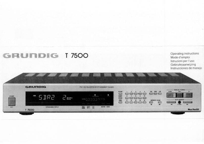
Grundig T 8200 MK II User manual

a
CD
Btx
*
32700
#
GRUMD
EG
service
manuat
10/88
a
_
____T
8200
MK
II
Inhaltsangabe
'
Seite
Contents
.
>
Page
Allgemeine
Hinweise
/Ausbauhinweise
2-3
General
Notes
/
Disassembly
Instructions
23
Ersatzteilliste
4-5
Spare
Parts
List
Boag
4-5
Sicherheitsvorschriften
?
79
Safety
Requirements
6-9
Abgleich
—
10-12
Alignment
10-12
Druckplatten
13-16
Printed
Circuit
Board
;
;
.
13-16
Schaltbild
17-24
Connection
Diagram
17-24
Sommaire
Page
Indice
.
Pagina
Contenido
.
:
Pagina
Instructions
de
démontage
D/GB
2-3
Note
riguardanti
lo
smontaggio
D/GB
2-3
Consejos
para
el
desmontaje
D/GB
2-3
Liste
de
piéce
détachées
D/GB/FA.
=
4-5
Lista
ricambi
D/GB/F/
4-5
Lista
de
piecas
de
repuestos
D/GB/F/I
4-5
*
Prescriptions
de
securite
D/GB/F//E
7-9
-
Prescrizioni
de
sicurezza
D/GB/F/VE
7-9
Recomendamos
de
seguridad
OIGBFIVE7-9
>
Alignement
D/GB/F/V/E
10-12
Taratura
D/GB/F/I/E
10-12
_Ajuste
D/GB/F/I/E
10-12
Circuits
imprimés
D/GB
13-16
Piastre
stampate
D/GB
13-16
Placa
de
C.I.
D/GB
13-16
Schéma
de
montage
D/GB/F//E
17-24
‘Schema
elettrico
D/GB/F/V/E
17-24
Esquema
D/GB/F/I/E
17-24
sede
mae
m+
ents
spatntnnni
ap
mapa
eA
NE
NINN
ean
eens
inary
egeicemnrnnenneg
OH
EO
term
leaner
A

-
Bei
Eingriffen
SchutzmaBnahmeh
fir
MOS-Bauteile
beachten!
Das
Gerat
muB
auch
nach
der
Reparatur
den
Sicherheitsbestimmu-
|
ngen
nach
DIN/IEC
65
VDE
0860
entsprechen.
MW
Abstimmung:
Das
MW-Raster
kann
fiir
USA
von
9
kHz
auf
10
KHz
geandert
werden.
MW-Taste
halten
und
Gerat
einschalten
=
10
kHz-Raster,
wiederho-
len
=.9
kHz-Raster.
Die
USA-Ausfiihrung
ist
ab
Werk
auf
10
kHz-
Raster
eingestellt.
lm
Display
erscheint
fiir
ca.
2
sec.
ein
U
fir
USA
oder
ein
E
fir
Europa.
FM
Abstimmung:
Das
Suchlauffenster
kann
fir
USA
von
15
kHz
auf
25
kHz
umge-
schaltet
werden.
FM-Taste
halten
und
Gerat
einschalten
=
25
kHz-
Fenster,
wiederholen
=
15
kHz-Fenster.
Die
USA-Ausflhrung
ist
ab
Werk
auf
25
kHz-Fenster
eingestellt.
lm
Display
erscheint
flr
ca.
2
sec.
ein
U
fur
USA
oder
ein
E
fir
Europa.
Ausbauhinweise
Gehaduseoberteil
-
6
Schrauben
a
herausschrauben.
|
Frontblende
Pa
-
3
Schrauben
b
hgrausschrauben..
.
-
Steckverbindung
ldésen::
Display
und
Displayplatte
7-4
Schrauben
c
herausschrauben.
Achtung
|
t
Abstandsrollen.
Displayplatte
-
Display
und
Displayplatte
ausbauen.
-
Schraube
d
herausschrauben.
-
Platte
vorsichtig
aus
den
Fihrungen
ziehen,
da
der
Flexprint
auf
der
Platte
aufgeklebt
ist.
lm
Reparaturfall
muB
das
Display
komplett
gewechselt
werden.
—
Lampenplatte
-
Lampe
90°
drehen
und
herausnehmen.
-
Rastnase
e
ausrasten
und
Lampenplatte
aus
den
Fihrungen
ziehen.
-
Beim
Einbau
darauf
achten,
daB
die
Leiterseite
oben
ist.
Bedienplatten
-
Frontblende
ausbauen.
-
Display
und
Displayplatte
ausbauen.
-
15
Schrauben
f
lésen.
Hauptplatte
-
5
Schrauben
g
herausschrauben.
-
6
Schrauben
h
herausschrauben.
Netzteilplatte
-
3
Schrauben
|
herausschrauben.
Netzschalterplatte
-
Netzschalter
ausrasten
und
Taste
abziehen.
-
-
Frontblende
abschrauben.
-
2
Schrauben
I
herausschrauben.
.
-
Netzschalter
und
-Platte
mit
Halterung
herausnehmen.
Trafo
oe
4
Schrauben
k
herausschrauben..
Halterung
fiir
Speicherbatterien
-
2
Schrauben
m
herausschrauben.
N.B.
When
carrying
out
repairs,
observe
MOS
precautions
|
After
the
unit
has
been
repaired,
it
should
still
meet
the
DIN/IEC
65
VDE
0860
safety
requirements.
:
MW
Tuning:
The
MW
channel
pattern
can
be
changed
from
9
kHz
steps
to
10
kHz
steps
for
US
version.
Push
the
MW
button
and
switch
on
the
unit
=
10
kHz
steps,
repeat
=
9
kHz
steps.
The
US
version
is
set
to
10
kHz
steps
by
the
factory.
For
about
two
seconds
an
U
for
US
or
an
E
for
Europe
lights
up
in
the
Display.
FM
Tuning:
The
FM
selfseek
pattern
can
be
changed
from
15
kHz
steps
to
25
kHz
steps
for
US
version.
Push
the
FM
button
and
switch
on
the
unit
=
25
kHz
steps,
repeat
=
15
kHz
steps.
The
US
version
is
set
to
25
kHz
steps
by
the
factory.
For
about
two
seconds
an
U
for
US
or
an
E
for
Europe
lights
up
in
the
Display.
Disassembly
Instructions
Cabinet
top
“
Undo
the
6
Screws
a.
Front.
panel
-
Unscrew
the.3
screws
6
Te
Disconnect
the
plug-
in
connections.
Display
and
Display
board.
=
Unscrew
the
4
screws
c
Take
care.
of
spacers!
Display
board
-
Remove
the
display
and
the
display
board.
-
Undo
screw
d.
-
Withdraw
the
board
carefully
from
the
guides
because
the
flexible
printed
circuit
board
is
glued
to
it.
If
repair
is
necessary,
the
complete
display
must
be
replaced.
Lamp
circuit
board
-
Turn
the
lamp
through
90°
and
remove
it.
-
Unlock
the
latch
e
and
withdraw
the
lamp
board
from
the
guides.
-
When
refitting
the
board
take
care
that
the
printed
side
faces
upwards.
Keyboard
circuit
boards
-
Remove
the
front
panel.
-
Remove
the
display
and
the
display
board.
-
Loosen
the
15
screws
f.
Main
circuit
board
-
Unscrew
the
5
screws
g.
-
Undo
6
screws
h.
Mains
board
-
Unscrew
the
3
screws
I.
Mains
switch
and
board
-
Release
the
power
switch
and
remove
the
button.
-
Undo
2
screws
i.
">
Remove
the
mains
switch
and
board
together
with
the
holding
—
device.
Transformer
-
Undo
the
4
screws
kK.
Holding
device
for
storage
batteries
-.
Undo
the
2
screws
m.


Part.No.
DESIGNATION
DENOMINAZIONE
Fig.|
Références
No.
ordine
Bedien!
:
.
(55110-810.01)
(55110-810.01)
(55110-810.01
(55110-810.01)
(kein
E-Teil}
(no
spare
parts)
(aucune
piese
de
rechange)
(nessun
pezzo
di
ric.)
1
55110-500.01
Frontblende
Front
mask
Ecran
frontal
Mascherina
frontale
2
55092-240.01
Tastenkappe
Push
button
cap
Capuchon
de
touche
Cappa
tasto
3
§5092-241.01
Tastenkappe
Push
button
cap
Capuchon
de
touche
Cappa
tasto
4
§50S92-243.02
Tastenkappe
Push
button
cap
Capuchon
de
touche
Cappa
tasto
5
55092-244.02
Tastenkappe
Push
button
cap
Capuchon
de
touche
Cappa
tasto
6
55092-245.02
Tastenkappe
Push
button
cap
Capuchon
de
touche
_
Cappa
tasto
7
§5092-242.02
Tastenkappe
_
Push
button
cap
Capuchon
de
touche
Cappa
tasto
8
55092-220.01
Power-Taste
Power-button
Touche-secteur
Tasto
di
rete
9
55110-300.01
Sichtscheibe
Viewing
disc
Fenetre
==
Vetrino
10
55092-230.01
Leuchtkérper
Light
element
Element
lumineux
Corpo
Iuminoso
11
§5110-820.01
Displaybaustein
Display
module
Element
d’affichage
Modulo
display
(55110-800.01)
(55110-800.01)
(6§5110-800.01)
(55110-800.01)
(kein
E-Teil)
(no
spare
parts)
{aucune
piese
de
rechange}
(nessun
spezzo
di
ric.)
§9752-068.01
Fuss
Foot
Pied
Piedino
§9752-069.00
Anti
Slip
Felt
Anti
slip
felt
Feutre
Feltro
antiscivolo
§9800-113.01
Batteriokasten
Batterie
case
Boitier
piles
Vano
batterie
§9800-099.01
Batteriedecke!
Battery
lid
Couvercle
da
batterie
Coperchio
batterie
§9600-071.00
AM-Loop-Areal
AM-Loop-Areal
Antenne
cadre
am
Antenna
atelaio
AM
§9600-072.00
Aerial-Hatlter
Aerial-holder
Support
d’antenne
Supporto
antenna
§9600-071.00
AM-Loop-Areal
AM-loop-Areal
Antenne
cadre
am
Antenna
a
telaio
AM
55110-210.00
Aeriai-selecteur
Aeriai-Selecteur
Selecteur
d’antenne
Selettore
antenna
59709-049.01
Wurfantenne
Wire
aerial
Antenne
volante
Antenna
a
filo
8290-991-201
Netzkabel
Mains
lead
Cable
secteur
Cavo
di
rete
09666-448.00
Zugentlastung
Tension
relief
Arret
de
cable
Fermacavo
09666-278.00
Hilse
Sleeve
Douille
Quaina
09667-064.01
.
Klemmstick
Shim
Piece
de
serrage
Pezzo
di
fissaggio
§9751-016.00
Kontaktrdéhrchen
Minature
contact
tube
Tube
de
contact
Tubetto
di
contatto
09666-487.97
Distanzstdck
Distance
piece
e
Entretoise
Distanziatore
§9352-934.94
Trafoplatte
Transformer
panel
Supporto
de
transfo
Supporto
trasformatore
§9400-305.00
Tipptaste
Push
button
Touche
Microtasto
§8400-321.00
Netzschalter
Mains
switch
_
Interrupteur
secteur
interruttore
di
rete
§9420-038.00
Frame
assy
Frame
assy
Cadre
Telaio
09621-236.01
Push
Terminal
Push
Terminal
Reccordement
Terminale
a
pressione
09623-417.02
Cinchbuchse
2-fach
Cinch
socket
2-way
Prise
cinch
2-fois
Presacinch
2-volte
09623-417.03
Cinchbuchse
2-fach
Cinch
socket
2-way
Prise cinch
2-fols
Presa
cinch
2-volte
09621-113.02
Sicherungshatter
Fuse
holder
Contact
de
fusbbile
Pontafusibile
09647-020.97
Ferritperie
Ferite
bead
Pere
ferrite
Perina
die
ferrite
«
!>
HINWEIS:
'
BAUELEMENTE
NACH
VDE-
BZW.
IEC-RICHTLINIEN.
IM
ERSATZFALL
NUR
TEILE
MITGLEICHER
~
_
SPEZIFIKATION
VERWENDENI
<!>
CAUTIONS:
COMPONENTS
TO
VDE
OR
IEC
GUIDELINES.
ONLY
USE
COMPONENTS
WITH
THE
SAME
SPECIFICATION
FOR
REPLACEMENT!
<!>
ATTENTION:
COMPOSANTS
CONFORMES
AUX
PRESCRIPTIONS
VDE
OU
IEC.
EN
CAS
DE
REMPLACEMENT
N’UTILISER
QUE
DES
COMPOS.
DE
MEMES
SPECIFICATIONS!
<!>
NOTA:
COMPONENTI
SECONDO
LE
NORME
VDE
RISP.
E
iEC.
IN
CASO
DI
SOSTITUZIONE
IMPIEGARE
SOLO
COMPONENTI
CON
LE
STESSE
CARATTERISTICHE!
ANDERUNGEN
VORBEHALTEN
-
ALTERNATIONS
RESERVED
-
TOUS
DROITS
DE
MODIFICATIONS
RESERVES
-
CON
RISERVA
DI
MODIFICHE
4

LL
'
Sachnummer
Part
number
|
DESCRIPTION
Références
DENOMINAZIONE
CD
DESIGNATION
.
.
No.
ordine
~.
19203-126.97
19203-126.97
19203-126.97
19203-
126.97
07202-730.10
07202-729.10
19203-124.14
19202-705.12
19202-704.12
17202-704.12
19202-702.12
19202-703.12
07202-728.12
07202-727.12
8140-526-862
8140-530-260
8140-530-240
09218-017.01
-.
8140-530-259
8140-530-258
8382-312-072
-.8602-331-001
8602-331-087
8305-262-217
8305-260-340
8305-260-166
8305-
100-522
8305-262-582
8305-278-744
8303-287-368
_
.B302-638-030
-
-
303-207-548
8303-406-240
»
8303-205-558
8303-205-558
8303-205-558
8303-406-240
8302-638-030
8302-638-030
8303-406-240
-8303-205-558
8303-205-548
8303-205-548
8303-205-548
8303-205-558
_
8302-991-044
8302-220-984
8302-220-095
8302-991-044
_.8303-406-240
303-406-240
8303-205-558
8303-205-548
8303-205-558
.
8303-205-558
_
8303-205-548
8303-205-548
8303-205-548
-
8140-526-025
|
.
4,19
MHz
8305-202-306
*~
BEZEICHNUNG
|
_DENOMINACION
CE
7,2
MHz
LC
7217
LA
3401
LA
1266.
78M
12CT
LC
7582
M
50744-966/SP
MC
78
M
06
CT
BC
368
2SK30_
BC
548C
BF
240
©
BC
558
B
BC
558
B
BC
558
B
BF
240
2
SK
30
235K
30
BF
240
—
BC
558
B:
-BC
548B
BC
548B
BC
548B
*
.
BC
SSBB.
28K
544E
-
BF
982-1
BF
240
2
SK
544
E
BF
240
BF
240
©
‘BC
5588
BC
548B
.
BC
558B
BC
558
B
BC
548
B
BC
548B
BC
5488
R
66
R67
R69
R
323
R
327
R
332
=
C2
C
305
C311
C
325
C
327
si
C1
C405
.
~
Sachnummer
|
-
Part
number:
Références
8309-215-043
8309-215-043
8309-217-321:
8309-217-321
8309-215-321
8309-215-321
—
8309-215-043
8309-215-043
~
8309-215-043
8309-215-043
8309-215-043
8309-215-043
8309-215-043
8309-215-043
8309-215-043
-
8309-215-043
8309-215-043
8309-215-043
-8309-215-043
8309-215-043
8309-215-043
8309-720-028
8309-251-310
8309-251-310
8309-251-310
8309-251-310
8309-215-006
8309-215-006
8309-215-006
8309-215-043
8309-215-043
8309-198-085
8309-215-043
8309-215-043
8309-215-043
8309-215-043
8309-925-024
8309-925-024
‘8309-925-024
oe
8790-050-064
8790-050-064
8790-050-064
8766-701-041
No.
ordine.
.
8309-215-006
-
8766-701-041
..
8766-701-027
ar
8699-999-356
8699-999-345
8699-999-345
8699-999-335
8699-999-345
8699-999-345.
8415-166-147.
‘
8660-097-241
09623-393.05
8316-454-520
8315-615-003
|
7,5/50
pF
630
MA/T
1N4151
1N4151
SVC
321
‘SVC
321
.|
SVC
321
SVC
321
1N
4151
1N
4151
1N
4151
1N4151
1N
4151
1N
4151
1N
4151
1N4151
‘|
1N
4151
‘tN
4151
|4N
4151
1N
4151
1N4151
1N4151
1N4151
ZD
2,7B
0,5
W
KV
1310
‘KV
1310
KV
1310
KV
1310
1N
4001
1.N
4001
1.N
4001
1.N
4001
1N
4151
1N
4151.
BAT
85:
1N
4151
1N4151
1
4N4151
1N4151
GL
9
HD
23
GL
9
HD
23
GLOHD
23
—
-
400.
Kohm
100
Kohm
100
Kohm
470hm
(I)
|.470hm
(I)
120hm
(I)
4,5/20
pF
4,5/20pF
3/10
pF
|
4,5,
/
20
pF
4,5:/20pF
330
pF
102°
{l)
T2V/0,1A
-BEZEICHNUNG
DESCRIPTION
DENOMINAZIONE
.
DESIGNATION
_
“DENOMINAGION
89800
1000
pF
/25V
Bedienungsanieitung
Instruction
book:
ss
|
‘Mode
d’emploi
ss
Insatruzioni
di
uso
(55110-941.01)”
--
ANDERUNGEN
VORBEHALTEN
-
ALTERNATIONS
RESERVED
-
TOUS
DROITS
DE
MODIFICATIONS
RESERVES
-
CON
RISERVA
DI
MODIFICHE

_
Sicherheltsvorschriften
/
Safety
requirements
/
Prescrizioni
de
sicurezza
/
Prescriptions
:
,
de
sécurité
/
Prescripciones
de
seguridad
oo
|
cia:
Bei
Eingriffen
ins
Gerat
Sind
die
Sicherheitsvor-
schriften
nach
VDE
701
(reparaturbezogen)
bzw.
VDE
0860
/
IEC
65
(geratebezogen)
zu
beachten!
Bauteile
nach
IEC-
bzw.
VDE-Richtlinien
|
Im
Ersatzfall
nur
Teile
mit
gleicher
Spezifikation
verwenden!
MOS
-
Vorschriften
beim
Umgang
mit
MOS
-
Bauteilen
be-
achten!
Attention:
Please
observe
the
applicable
safety
recuiie:
ments
according
to
VDE
701
(concerning
repairs)
and
VDE
0860
/
IEC
65
(concerning
type
of
product)!
/N
AN
Components
to
IEC
or
VDE
guidelines!
Only
use
compo-
nents
with
the
same
specifications
for
replacement!
Observe
MOS
components
handling
instructions
when
ser-
vicing!
Attenzione:
Osservame
le
corrispondenti
prescrizioni
di
sicurezza
VDE
701
(concernente
servizio)
e
VDE
0860/1EC
65
(concernente
il
tipo
di
prodotto)!
Componenti
secondo
le
norme
VDE
risp.
te
IEC!
Inc
caso
di
sostituzione
i
eee
solo
neon
con
le
stesse
carat-
teristiche.
.
Osservare
le
relative
prescrizioni
durante,
lavori
con.
com-
ponenti
MOS!
:
D>
Sicherheitsbestimmungen
CFD
Prescriptions
de
Sécurite
Sicherheitsbestimmungen
Nach
Servicearbeiten
ist
bei
Geraten
der
Schutzklasse
ll
die
Mes-
sung
des
Isolationswiderstandes
und
des
Ableitstromes
bei
einge-
schaltetem
Gerat
nach
VDE
0701
/
Teil
200
bzw.
der
am
Aufstellort
geltenden
Vorschrift,
durchzufiihren!
|
Dieses
Gerat
gestalt,
der
Schutzklasse
il,
erkennbar
durch
das
Symbol
.
.
@
Messen
des
Isolationswiderstandes
nach
VDE
0701.
lsolationsmesser
(U
,,.,
=
=
500
V-)
gleichzeitig
an
beiden
Netzpo-
len
und
zwischen
allen
n
Gehduse-
oder
Funktionsteilen
(Antenne,
Buchsen,
Tasten,
Zierteilen,
Schrauben,
usw.)
aus
Metall
oder
Metallegierungen
anlegen.
Fehlerfrei
ist
das
Gerat
bei
einem:
R
.)
2
2
MQ
bei
U
=
500
V-.
iso!
~
Test
MeBzeit:
>
1s
(Fig.
1)
Anmerkung:
Bei
Gerdten
der
Schutzklasse
II
kann
durch
Entla-
dungswiderstande
der
MeBwert
des
Isolationswiderstandes
-kon-
struktionsbedingt
<
2
MQ
sein.
In
diesen
Fallen
ist
die
Ableitstrom-
messung
maBgebend.
Prifling
Test
item
Apparecchio
in
misura
Piéce
d’essai
Aparato
de
prueba
Netzstecker
des
Priflings
Mains
plug
of
test
item
Spina
di
rete
dell
‘apparecchio
j
in
misura
Fiche
secteur
piéce
de
essai
Clavija
de
red
del
aparato
de
prueba
Prifling
Test
item
Apparecchio
in
misura
Piéce
d’essai
Aparato
de
prueba
=
MOnUC)
METRATESTER
3:
Netzstecker
des
Priflings
Mains
plug
of
test
item
Spina
di
rete
dell‘apparecchio
in
misura
Fiche
secteur
piéce
de
essai
Clavija
de
red
del
aparato
de
prueba
[oT
nn
METRATESTER
3
Fig.
2
|
Safety
Standard
Compliance
Cc
Disposiciones
para
la
Seguridad
Attention:
Priere:
d'observer
les.
seeonptions
de
securite
VDE
701
(concernant
les
reparations)
et
VDE
0860
/
ie
65
(concernant
le
type
de
produit)!
Composants
répondant
aux
normes
VDE
ou
IEC.
Les
rem-
placer
uniquement
par
des
composants
ayant
les
memes
spécifications.
Lors
de
la
manipulation
des
circuits
MOS,
respecter
les
pescriptions
MOS!
:
Atencién:
Recomendamos
las
normas
de
seguridad
VDE
u
otras
normas
equivalentes,
por
ejemplo:
VDE
701
para
re-
paraciones,
VDE
0860
/
IEC
65
para
aparatos!
Componentes
que
cumplen
las
normas
VDE/IEC.
En
caso
AN,
de
sustitucién,
emplear
componentes
con
nidénticas
especi-
ficaciones!
Durante
la
reparacion
observar
las
normas
sobre
com-
ponentes
MOS!
Ce)
Aitention:
This
set
can
only
be
operated
from
AC
mains
of
120
V/60
Hz.
Also
observe
the
information
given
on
the
rear
of
the
set.
CAUTION-for
continued
protection
against
risk
of
fire
re-
place
only
with
same
type
fuses!
CAUTION:
to
reduce
the
risk
of
electric
shock,
do
not
re-
move
cover
(or
back),
no
user-serviceable
parts
inside,
refer
servicing
to
qualified
service
personnel.
Observe
MOS
components
handling
instructions
when
servicing}.
Ma
rN’
‘C1_>
Norme
di
Sicurezza
-
Safety
Instructions
@
Messen
des
Abieitstromes
nach
VDE
0701.
Ableitstrommesser
(U
,,.,
=
220
V=)
gleichzeitig
an
beiden
Netzpolen
und
zwischen
allen
Gehause-
oder
Funktionsteilen
(Antenne,
Buchsen,
Tasten,
Zierteilen,
Schrauben,
usw.)
aus
Metall
oder
Metallegierungen
anlegen.
Fehlerfrei
ist
das
Gerat
bei
einem:
|
splot
<
1
mA
bei
Us,
=
220V
=
MeBzeit
>
1
s
(Fig.
2)
_@
Wir
empfehlen
die
Messungen
mit
dem
METRATESTER
3
durchzufiihren.
(Metoorst2
zur
Prafung
elektrischer
Gerate
nach
VDE
0701).
Metrawatt
GmbH
Geschaftsstelle
Bayern
Triebstr.
44.
D
8000
Munchen
50
@
Ist
die
Sicherheit
des
Gerates.
nicht
siccbent
well
-
eine
Instandsetzung
unmdglich
ist
~_
-
oder
der
Wunsch
des
Benititzers
besteht,
die
Instandsetzung
nicht
durchfdhren
zu
lassen,
so
muB
dem
Betreiber
die
vom
-
Gerat
ausgehende
Gefahr
schriftlich
mee
werden.
Mit
der
Greifklemme
alle
Metallteile
u.
metallisierten
Teile
abtasten.
All
metal
and
metallic
parts
must
be
tested
with
the
Caliper
clamp.
Con
cavo
provvisto
di
morsetio
toccare
tutte
le
parti
metalliche
°
metallizzate.
A
l'aide
dune
pince
vérifier
toutes
les
parties
métalliques
ou
métallisées.
Con
la
pinza,
tocar
todas
las
piezas
metalicas
o
motaizadas’
‘
Netzstecker/Mains
plug/Spina
di
rete/Fiche
secteur/Clavija
de
red
it
der
Greifklemme
alle
Metallteile
u.
metallisierten
Teile
abtasten.
.
Allmetal
and
metalised
parts
must
be
tested
with
the
Caliper
clamp.
_Con
cavo:provwvisto.di.morsetto
toccare
tutte
le
parti
metalliche
o
metallizzate.
A
\’aide
d’une
pince
vérifier
toutes
les
parties
métalliques
ou
métallisées.
Con
ia
pinza,
tocar
todas
las
piezas
metalicas
o
metalizadas.
Netzstecker/Mains
plug/Spina
di
rete/Fiche
secteur/Clavija
de
red

Empfehlungen
fiir
den
Servicefall
e@
Nur
Original
-
Ersatzteile
verwenden.
Bei
Bauteilen
oder
Baugruppen
mit
der
Sicherheitskennzeichnung
sind
Original
-
Ersatzteile
zwingend
notwendig.
@
Auf
Sollwert
der
Sicherungen
achten.
@
Zur
Sicherheit
beitragende
Teile
des
Gerates
dirfen
weder
be-
schadigt
noch
offensichtlich
ungeeignet
sein.
®
Dies
gilt
besonders
fir
lsolierungen
und
Isolierteile.
@
Netzleitungen
und
AnschluBleitungen
sind
auf
AuBere
Mangel
vor
dem
AnschluB
zu
prifen.
Isolation
prifen!
@
Die
Funktionssicherheit
der
Zugentlastung
und
von
Biegeschutz-
Tullen
ist
zu
prifen.
@
Thermisch
belastete
Létstellen
absaugen
und
neu
(6ten.
e
Beluftungen
frei
lassen.
|
Safety
Standard
Compliance
After
service
work
on
a
product
conforming
to
the
Safety
Class
Il,
the
insulating
resistance
and
the
leakage
current
with
the
product
switch
on
must
be
checked
according
to
VDE
0701
or
to
the
specification
valid
at
the
installation
location!
This
a
conforms
to
the
Safety
Class
li,
as
identified
by
the
symbol
[6
e@
Measurement
of
the
Insulation
Resistance
to
VDE
0701,
Connect
an
Insulation
Meter
(U
Test
=
200
V-)
to
both
mains
poles
simultaneously
and
between
ail
cabinet
or
functional
parts
(anten-
na,
sockets,
buttons,
decorative
parts,etc.)
made
from
metal
or
metal
alloy.
The
product
is
fault
free
if:
Ry
2
2
MQ
at
U
5,
=
500
V-
Measuring
time:
=
1s,
(Fig.
1)
Comment:
On
product
conforming
to
the
Safety
class
II
the
jastsstion
Resistance
can
be
<
2
MOhm,
dependent
contructively
on
discharge
resistors.
In
this
cases,
the
check
of
the
leakage
currentis
significant.
@
Measurement
of
the
Leakage
Current
to
VDE
0701.
Connect
the
Leakage
Current
Meter
(U
,..,
=
220
V=)
to
both
mains
poles
simultaneously
and
between
all
cabinet
or
functional
parts
(antenna,
sockets,
buttons,
screws,
etc.)
mad
from
metal
or
metal
alloy.
The
product
is
fault
free
if:
leak
©
mA
at
U
+5
=
220
V
=
Measuring
time:
2
1
s,
(Fig.
2)
@
We
recommend
that
the
measurements
are
carried
out
using
the
METRATESTER
3.
(Test
equipment
for
pecnna's
electrical
pro-
ducts
to
VDE
0701).
Metrawatt
GmbH
Geschiftsstelle
Bayern
Triebstr.
44
D
8000
Ménchen
50
@
If
the
safety
of
the
product
is
not
proved,
because
-
arepair
and
restoration
is
impossible
-
orf
the
request
of
the
user
is
that
the
restoration
is
not
to
be
carried
out,
the
operator
of
the
product
must
be
wamed
of
the
danger
by
a
written
warning.
Recommendation
for
service
repairs
©
Use
only
original
spare
parts.
With
components
or
assemblies
accompanied
with
the
Safety
Symbol
A\
only
original-spare
parts
are
strictly
to
be
used.
@
Use
only
original
fuse
value.
,
@
Safety
compliance,
parts
of
the
product.
must
not
be
visually
damaged
or
unsuitable.
This
is
valid
especially
for
insulators
and
insulating
parts.
@
Mains
leads
and
connecting
leads
should
be
checked
for
external
_
damage
before
connection.
Check
the
insulation!
@
The
functional
safety
of
the
tension
relief
and
bending
protection
bushes
are
to
be
checked:
@
Thermally
loaded
solder
pads
are
to
be
suck
off
and
re-soldered.
@
Ensure
that
the
ventilation
slots
are
not
obstructed.
<P
Norme
di
sicurezza
Successivamente
ai
lavori
di
riparazione,
negli
apparecchi
della
classe
di:protezione
II
occorre
effettuare
la
misura
della
resistenza
di
isolamento
e
della
corrente
di
dispersione
quando
|l’apparecchio
e’acceso,
secondo
le
norme
VDE
0701./
parte
200
e
rispettivamente
le
norme
locali!
Questo
apparecchio
corrisponde
alla
classe
di
protezione
ll
ed
é
riconoscibile
dal
simbolo
[E]
.
@
Misura
della
resistenza
di
isolamento
secondo
VDE
0701
-
Applicare
il
misuratore
di
isolamento
(tens.
nova
=
500
V-)
contem
poraneamente
ai
due
poli
di
rete
e
tra
tutte
le
‘parti
del
mobile
e
delle
funzioni
(antenna,
prese,
tasti,
mascherine,
viti
ecc.)
in
metallo
o
in
lega
metallica.
L'apparecchio
non
presenta
difetti
quando:
R
igo)
2
2
MQ
con
tens.
oi
=
500
V-"
Pas
3
S
he
cue
Tempo
di
misura:
2
ts
(Fig.
1).
.
Nota:
Negli
apparecchi
della
classe
II,
che
per
motivi
costruttivi
dispongono
di
resistenze
di
dispersione,
il
valore
di
misura
della
resistenza
di
isolamento
pué
essere
inferiore
a<
2
MQ...
In
questi
casi
6
determinante
la
misura
della
corrente
di
dispersione,
°
Misura
della
corrente
di
dispersione.
secondo
VDE
0701
Applicare
il
misuratore
di
isolamento
(tens.
prova:™.
=
220
V=)
contem-
poraneamente
ai
due
poli
di
rete
e
tra
tutte
le
parti
del
mobile
e
delle
funzioni
(
antenna,
prese,
tasti,
mascherine,
viti
ecc.)
in
metallo
o
in
lega
matallica.
L’"apparecchio
non
presenta
difetti
quando:
|
disp.
-<i1mAcon
tens.
prova
=
220
Vz=
Tempo
di
misura
:
2
1
s
(Fig.
2)
e
Si
raccomanda
di
effettuare
le
misure
con
lo
strumento
METRATE-
STER
3
(strumento
di
misura
per
il
controllo
di
sepseeds
elettrici
~
secondo
VDE
0701).
Metrawatt
GmbH
Geschaftsstelle
Bayern
Triebstr.
44
D
8000
Munchen
50
@
Se
la
sicurezza
dell'apparecchio
non
6
raggiunta,
perch
-
una
riparazione
non
é
possibile
.
_-.
oppure
é@
desiderio
del
cliente
che
una
riparaz.
non
avvenga
in
_
questi
casi
si
deve
comunicare
per
iscritto
all’utilizzat.
la
perico-
losita
dell’apparecchio
riguardo
il
suo
isolamento.
Raccomandazione
per.
il
servizio
assistenza
|
@
Impiegare
solo
componenti
originali:
|
componenti
o
i
gruppi
di
component
contraddistinti
dall’
indicaz.
-devono
assolutamente
venir
sostituiti
con.
parti
originale.
7
©
»
Osservare
il
valore
nominale
dei
fusibili.
-
@
|
componenti
che
concorrono
alla
sicurezza
dell
‘apparecchio
non
possono-essere:né
danneggiati
né
risultare
visibilmente
inadatti.
Questo
vale
soprattutto
per
isolamenti
e
parti
isolate.
@
|
cavi
di
rete
e
di
collegamento
vanno
controllati
prima
dell'utilizzo-
affinché
non
presentino
imperfezion!
esteriori.
Controllare
lisola
mento.
.
@
E‘necessario
controllare
la
sicurezza
dei
fermacavi
e
delle
guaine
flessibili.
@
Saldature
caricate
termicam.
vanno
rifatte.
@
Lasciare
libere
le
fessure
di
areazione.

CF
Prescriptions
de
securite
Suite
aux
travaux
de
maintenance
sur
les
appareils.
de
la
classe
i,
il
convient
de
mesurer
la
résistance
d'isolement
et
le
courant
de
tuite
sur
l'appareil
en
état
de
marche,
contormément
4
la
norme
VDE
0701
§
200,
ou
selon
les
prescriptions
en
vigueur
sur
le
lieu
de
tonctionne-
ment
de
l'appareil!
Cet
appareil
est
contorme
aux
prescriptions
de
sécurité
classe
Il
signaléé
par
le
symbole
[6
@
Mesure
de
la
resistance
d‘isolement
selon
VDE
0701
_
Brancher
un
appareil
de
mesure
d'isolaton
(U
,,,,
=
500
V-)
simul-
tanment
sur
les
deux
pdles
secteur
et
entre
toutes
les
parties
métalliques
ou
métallisées
accessibles
de
l'appareil
(antenne,
em-
bases,
touches,
enjoliveurs,
vis,
etc.).
Le
tonctionnement
est
correct
oun
R
jeg)
2
2
MQ
pour
une
US
:
500V-
Durée
de
la
mesure:
2
i
Observations:
L'isolation
des
appareils
de
la
classe
Il,
de
part
leur
conception
résistance
de
décharge),
peut
étre
intérieur
a
<
2
MQ,
(Fig.
1).
@
Mesure
du
courant
de
fuite
selon
VDE
0701.
7
Brancher
un
ampéremétre
du
courant
de
fuite
(U
,,.,
=
220V=)
simultanément
sur
les
deux
péles
du
secteur
et
entre
toutes
les
parties
métalliques
ou
métallisée
accessibles
de
l'appareil
(anten-
ne,
embases,
touches,
enjoliveurs,
vis,
etc.).
Le
tinctionnement
est
correct
lorsque
(Fig.
2):
lute
IMA
pour
U,,.,
:
200
Ve=
Durée
de
la
mesure
2
1
s.
@
Pour
ces
mesures,
nous
préconisons
1°
Utilisation
du
METRATE-
STER
3
(instrument
de
mesure
pour
le
contréle
d’
ap
pareils
élec-
triques
conformes
4
la
norme
VDE
0701).
METRAWATTWATT
GmbH
Geschfftsstelle
Bayern
Triebstr.
44
D
8000
Munchen
50
@
Dans
le
cas
ou
la
sécurité
de
l'appareil
nést
pas
assurée
pour
les
aisons
suivantes:
-
laremise
en
état
est
impossible
|
-
Tutilisateur
ne
souhaite
pas
la
remise
en
état
de
l'appareil.
lutili
sateur
doit
6tre
informé
par
écrit
du
danger
que
paket
utili
sation
de
l'appareil.
Recommandations
pour
la
maintenance
@
Utiliser
exclusivement
des
piéces
de
rechange
d'origine.
Les
com
posants
et
ensembles
de
composants
signalés
par
le
symbole
A
doivent
étre
impérativement
remplacés
par
des
piéces
d’origine.
@
Respecter
la
valeur
nominale
des
tusibles.
®
Veiller
au
bon
état
et
la
conformité
des
piéces
contribuant
a
la
sécurité
de
tonctionnement
de
l'appareil.
Ceci
s’applique
particulié-
rement
aux
isolements
et
piéces
isolantes.
@
Véritier
le
bon
état
extérieur
des
cables
secteur
et
des
cables
de
raccordement
au
point
de
vue
isolement
avant
la
mise
sous
tension.
@
Véritier
le
bon
état
des
protections
de
gaine.
@
Nettoyer
les
soudures
avant
de
les
renouveler.
@
Dégager
les
voies
d’aération.
CED
DISPOSICIONES
PARA
LA
SEGURIDAD
Después
de
operaciones
de
servicio
en
aparatos
de
la
clase
de
proteccion
li,
se.
llevara
a-cabo
la
medida
dela
resistencia
de
aislamiento
y
de
la
corriente
derivada,
con
el
aparato
conectado,
de
acuerdo
con
VDE
0701
ode
las
disposiciones
vigentes
en
el
lugar
de
instalacion
.
Este
aparato
corresponde
a
la
clase
de
proteccién
ll,
reconocible
por
el
simbolo
[J]
.
Medida
de
la
resistencia
de
aislamiento
segun
VDE
0701.
Aplicar
el
medidor
de
aislamiento
(U
nuaba
=
500
V-),
simultanea-
mente,
a
los
dos
polos
de
red
y
entre
todas
las
partes
del
mueble
o
de
funciones
(
antena,
conectores,
teclas,
tornillos,
etc.)
de
matal
o
aleaciones
metalicas.
El
aparato
estara
libre
de
defectos
con:
R
ais}
2
2
MQ
con
U
ba
‘=
500
V-
ais
prue
Tiempo
de
medida
2
1
seg.
Observacién:
En
aparatos
de
la
clase
de
protweceion
H,
peindicionade
por
la
construccién
y
por
resistencias
de
descarga,
el
valor.de
medida
de
la
resistencia
de
aislamiento
puede
ser
superior
a
<2
MQ.
5
En
este
caso
es.
decisiva
la
meas
sed
la
corriente
derivada
(Fig.
1).
@
Medida
de
la
corriente
duvivads
de
seueeds:
con
n
VDE
0701.
Aplicar‘el
medidor
de
corriente
derivada
(U
reba
=
220
Ve)
simul-
taneamente
a
los
dos
polos
de
red
y
entre
todas
las
partes
del
mueble
o
de
funciones
(antena,
conectores,
teclas,
tornillos,
etc.)
de
matal
o
aleaciones
metalicas.
El
peas
estara
libre
es
defectos
con
(Fig.2):
|
bey
1
MA
con
U-
ileba
=
220
V=.
-
Tiempo
de
medida
:
2
1
seg.
@
Aconsejamos
fievar
a
cabo
las
medidas.
con
el
METRATESTER
3
(Instrumento
de
medida
para
la
comprobacion
de
aparatos
eléctri-
“cos
segun
VDE
0701)...
.
METRAWATT
GmbH
Geschaftsstelle
Bayern
-Triebstr.
44
D
8000
Munchen
50
@
Si
no
se
cumple
la
seguridad
del
aparato,
poroue
-
-
la
puesta
en
orden
es
imposible,
o
-
«
@siste
el
desco
del
usuario
de
no
realizarla,
se
ha
de
comunicar
..
aquienlo
haga
funcionar,
por
escrito,
del
61
peligro.
dimanante
del
..
aparato.
-
pasonisndaciones
para
caso
de
servicio
@
Emplear
sélo
componentes
originales.
Con
componentes
o
grupos
constructivos
con
el
indicativo
de
se
guridad
TaN
son
de
obligada
necesidad
piezas
de
repuesto
origina-
“les.
~~
@
Las
vartes
del
aparato
que
contribuyan
a
la
seguridad
del
mismo:no
deben
estar
deterioradas
ni
ser
manifiestamente
inadecuadas.
@
Esto
es
especialmente
valido
para
aislamientos
0
piezas
aislantes.
@
Los
cables
de
red
y
de
conexi6n
se
comprobaran,
antes
de
concc
tarlos,
en
cuanto
a
defectos
externos.
Comprobar
el
aislamiento.
@.Se
ha
de
comprobar
la
funcién
de
seguridad.de
la
compensacién
de
tiro
o
de
los
manguitos
de
proteccién
contra
doblamientos..
®@
Repasar
los
puntos
de
soldadura
sometidos
a
carga
térmica.
@
Mantener
libres
los
canales
aireaci6n.

Safety
Instructions
A
A
The
lightning
flash
with
arrowhead
symbol,
within
an
equila-
teral
triangle,
is
intended
to
alert
the
user
to
the
presence
of
uninsulated
“dangerous
voltage”,
within
the
product’s
enclo-
sure
that
may
be
of
sufficient
magnitude
to
constitute
a
risk
of
electric
shock
to
persons.
The
exclamation
point
within
an
equilateral
triangle
is
inten-
ded
to
alert
the
user
to
the
presence
of
important
operating
and
maintenance
(servicing)
instructions
in
the
literature
ac-
companying
the
appliance.
This
product
was
designed
and
manufactured
to
meet
strict
quality
and
safety
standards.
There
are,
however,
some
Installation
and
operation
precautions
which
you
should
be
particularly
aware
of.
Read
Instructions
-
All
the
safety
and
operating
instructions
should
be
read
before
the
appliance
is
operated.
Retain
Instructions
-
The
safety
and
operating
instructions
should
be
retained
for
future
reference.
Heed
Warnings
-
All
warnings
on
the
appliance
and
in
the
operating
instructions
should
be
adhered
to.
Follow
Instructions
-
All
operating
and
use
instructions
should
be
followed.
Water
and
Moisture
-
The
appliance
should
not
be
used
near
water-for
example,
near
a
bathtub,
washbowl,
kitchen
sink,
laundry
tub,
in
a
wet
basement,
or
near
a
swimming
pool,
and
the
like.
Wall
or
Ceiling
Mounting
-
The
appliance
should
be
mounted
to
wall
or
ceiling
only
as
recommended
by
the
manufacture.
Ventilation
-
The
appliance
should
be
situated
so
thatits
loca-
tion
or
position
does
not
interfere
with
its
proper
ventilation.
For
example,
the
appliance
should
not
be
situated
on
a
bed,
sofa,
rug,
or
similar
surface
that
may
block
the
ventilation
openings;
or,
placed
in
a
built
-
in
installation,
such
as
a
bookcase
or
cabinet
that
may
impede
the
flow
of
air
through
the
ventilation
openings.
Heat
-
The
appliance
should
be
situated
away
from
heat
sources
such
as
radiators,
heat
registers,
stoves,
or
other
appliances
(including
amplifiers)
that
produce
heat.
x1
x2
Power
Sources
-
The
appliance
should
be
connected
to
a
power
supply
only
of
the
type
given
above
or
as
marked
on
the
appliance.
Power-Cord
Protection
-
Power-supply
cords
should
be
rou-
ted
so
that
they
are
not
likely
to
be
walked
on
or
pinched
by
items
placed
upon
or
against
them,
paying
_
particular
attention
to
cords
at
plugs,
convenience
receptacles,
and
the
point
where
they
exit
from
the
appliance.
Cleaning
-
The
appliance
should
be
cleaned
only
as
recom-
men
ded
by
the
manufacturer.
Power
Lines
-
An
outdoor
antenna
should
be
located
away
from
power
lines.
Outdoor
Antenna
Grounding
-
If
an
outside
antenna
is
connected
to
the
receiver,
be
sure
the
antenna
system
is
grounded
so as
to
provide
some
protection
against
voltage
—
surges
and
built
up
static
charges.
Section
810
of
the
National
Electrical
Code,
ANSI
/
NFPA
No.
70-1984,
provides
informa-
tion
with
respect
to
proper
grounding
of
the
mast
and
suppor-
ting
structure,
grounding
of
the
lead-in
wire
to
an
antenna
discharge
unit,
size
of
grounding
conductors,
location
of
antenna
discharge
unit,
connection
to
grounding
electrodes,
and
requirements
for
the
grounding
electrode.
Nonuse
Periods
-
The
power
cord
of
the
appliance
shold
be
un
plugged
from
the
outlet
when
left
unused
fora
long
period
of
time.
Object
and
Liquid
Entry
-
Care
should
be
taken
so
that
objects
do
not
fall
and
liquids
are
not
spilled
into
the
enclosure
through
openings.
Damage
Requiring
Service
-
The
appliance
should
be
servi-
ced
by
qualified
service
personnel
when:
The
power-supply
cord
or
the
plug
has
been
damaged;
or
objects
have
fallen,
or
liquid
has
bee
spilled
into
the
appliance;
or
the
appliance
has
been
exposed
to
rain;
or
the
appliance
does
not
appear
to
operate
normally
or
exhibits
a
marked
change
in
perfor-
mance;
or
the
appliance
has
been
dropped,
or
the
enclosure
damaged
;
or
the
batteries
have
been
damaged.
Servicing
-
the
user
should
not
attempt
to
service
the
applian-
ce
beyond
that
described
in
the
operating
instructions.
All
other
servicing
should
be
referred
to
qualified
service
person-
nel
.
Points
x1
and
x2
apply
only
to
receivers
or
tuners.
CD
XGECFC
IDCED
-
Abgleich
-
Einspeisung
+
MeBpunkt
«
Hinweise
°
fiieueat
bk
.
Maen
*
Abgleich
¢
Alignment
¢
Feeding
*
Testpoint
*
Notes
e
Baint
ere
*
Alignment
*
Alignement
*
Injection
*
Point
de
mesure
*
Observation
d’alignement
—
*
Alignement
|
+
Taratura
¢
Alimentatione
*
Punto
di
misura
*
Note
«Punto
ditaratural
°
Rego
azione
*
Taratura
*
Ajuste
*
Aplicaci6n
de
sefal
|
+«
Punto
de
medida
¢
Advertencias
°
Punto
de
ajuste
-
Ajuste
*
Ajuste
-
Feldstiirke-
pegel
108
MHz
¢
Oszillator
*
Oscillator
¢
Oscillateur
'
«
Oscillatore
*
Oscilador
réception
1,0V
*
Livello
intensita’
di
campo
|
*
Intensidad
de
|
campo
(VU)
522
kHz
153
kHz
me,
106
MHz
(2)
261
kHz
a
|
OM
| !
|-
Field
strengt
87,5
MHz
(
;
)
2,5V
level
*
Niveau
de
|
—
Suchlaufpegel
|
|
°
Self
seek
level
|
|
°Niveau
en
recherche
automatique
*
Livello
ricerca
automatica
*
Nivel
de
exploracién
de
sintonla
¢
Nachbar-
kanalfiiter
*
Adjacent
channel
filter
¢
Filtre
canal
adjacent
Filtro
per
canale
adiacente
*
Filtro
del
canal
adyacente
*
Vor-u.
Zwi-
schenkreis
¢
Aerial
band
pass
cct.
°
Circuits
.
préliminaire
et
intermédiaire
¢
Circuito
ingresso
ed
intermedio
*
Circuitos
de
antena
e
intermedio
*
Pilot-und
Hilfstrager
*
Pilotcarrier
and
subcarrier
*
Porteuse
pilote
et
sous-porteuse
|_*
Portante
pilota
e]
ausiliaria
«
Portadoras
piloto
y
auxiliar
¢
Abgleich
nach
Rauschen
_
¢
Alignment
by
noise
Réglage
au
maximum
de
bruit
*
Taratura
in
base
al
fruscio
+
Ajuste
segun
el
ruido
Zeichenerklarung
*
Stereo-Uber-
sprechdam-
pfung
_
©
Stereo
\
crosstalk
attenuation
oo
¢
Minimum
¢
Minimum
°
Minimum
¢
Minimo
¢
Minimo
Z
Atténuation
de
la
diaphonie
¢
Attenuazione
i
della
diafonia
stereo
«
Atenuacién
de
diafonia
stereo
else

_«
Hinwelse
1°
Abgieichpunkt]
Einstellung
pada
-
Einstellung
-
Abgleich
-
Elnspeisung
*
MeBpunkt
)
bale
«
Adjustment
°
Alignment
|
¢
Feeding
¢
Testpoint
°
Notes
°
ar
point}
Adjustment
nement
*
Reglage
*
Alignement
*
Injection
¢
Point
de
mesure
¢
Observation
ae
oint
*
Réglage
ditaratural
°
egolazione
°
Taratura
*
Alimentatione
¢
Punto
di
misura
¢
Note
ee
cae
|
+»
Regolazione
de
ajuste
»
Ajuste
*Ajuste
|
°
Aplicacién
de
sefial
|
+
Punto
de
medida
¢
Advertencias
Paniede
alliste
+
Ajuste
85V
:
Feldstarke-
|
°
Einstellen,
daB
:
letztes
Segment
Beas
reatieeiel
el
ni
«
Adjust
that
the
last
|
oon
-
Niveau
de
|
°
ees
segment
just
lights
up
: :
Régler
de
fagon
a
ce
réception
*
Atticheur
que
le
dernier
1,0V
°
Livello
¢
Display
segment
s'allume
.
intensita’
¢
Display
faiblement
di
campo
*
Regolare
in
modo
|
1,8V
|¢
Intensidad
de
che
ae
segmento
:
lrisulti
appena
acceso
Sameer)
°
Aue
Display
de
manera
que
empiece
a
brillar
el
dltimo
—
segmento
Suchlaufpegel
|
«Self
seek
level
*
Suchlaufstopp
*
Self
seek
stop
.
Ue
<
15
uv
>
kein
*
Niveau
en
recherche
Stopp
/
no
stop
/pas
/
¢
Arret
en
recherce
automatique
manca
stop
/
no
para
automatique
(<)
ss
*
Livello
ricerca
*
Stop
ricerca
e
automatica
e
215
pV
>
Stopp
automatica
|
ts
-
Nivel
de
/
stop
/
arret
/
stop
/
»
Paro
de
biisque-
Z
an
exploracién
de
para
da
automatica
ot
aq
oo
sintonia
¢
Nachbar-
¢
Das
Filter
ist
(i)
@e
a®
@ea
kanalfilter
+
Adjacent
eer
cet
*
Minimum
pannel
filter
preadjusted
¢
Minimum
my
re.conel
+
Le
filtre
est
°
Minimum
z
Fino
Der
capale
_
prérégié
¢
Minimo
a
adiacente
°
I
filtro
e"
pretarato
*
Minimo
°
Filtro
del
canal
*
Este
filtro
viene
adyacente
preajustado
*
Minimum
*
Pilot-und
inl
Hilfstrager
°
Minimum
=
*
Pilotcarrier
and
°
Minimum
@
<
()
ip
‘0
subcarrier
¢
Minimo
Cu)
*
Minimo
<
*
Porteuse
pilote
et
sous-porteuse
QD
|NOJOWLW
OOM
Yow
Portante
pilota
e
oe
ausiliaria
*
Minimum
*
Portadoras
°
Minimum
—
piloto
y
auxiliar
¢
Minimum
*
Minimo
¢
Minimo
ORY,
on
MeBsender/T
estgenerator
NF-Voltmeter/AF-Voltmeter
x
(©)
a
Générateur/Generatore
di
misura
Voltmétre
BF/Voltmetro
BF
|
Generador
frecuencias
Voltimetro
de
BF
N
NF-Generator/AF-Generator
Digitalvoltmeter/Digital
voltage
meter
Générateur
BF/Generatore
BF
Voltmétre
digital/Voltmetro
digitale
NS
Generador
de
BF
Voltimetro
digital
,
e
=
.
Stereogenerator/Stereo-Generator
:
.
GleichspannungsmeBgerat/DC
voltage
meter
—e
0
Générateur
de
Stéréo/Generatore
di
Stereo
Voltmétre
DC/Misuratore
tensione
continua
Generador
de
Stereo
|
Medidor
de
tensi6n
continua
:
(<)
2A
C
¢
Minimum
¢
Minimum
°
Minimum
¢
Minimo
¢
Minimo
Antenne/Aerial
Oszilloskop/Oscilloscop
Cadre/Antenna
Oscilloscope/Oscilloscopio
Antena
Osciloscopio
Rahmenantenne/Frame
aerial
Einstellung
wiederholen/To
repeat
the
adjustment
Cadre/Antenna
a
telaio
Répéter
le
réglage/Ripetere
la
regolazione
Antena
de
cuadro
Repetir
el
adjuste
11
|
12

Druckplatten
T
8200
MK
II
-
Lotseite
| |
|
a
Printed
Circuit
Boards
T
8200
MK
Il
-
Solder
side
NETZ
/
MAINS
:
2
10V
ag
ee
ee
Ha
ee
ED
ie
13
14

yee
;
15
16

il
aR
ANTENNA
SECTION
PARTIE
FM
ANTENNE
SEZIONE
FM-ANTENNA
AM-ANTENNEN-TEIL
AM
ANTENNA
SECTION
PARTIE
AM
ANTENNE
SEZIONE
AM-ANTENNA
FM-ANTENNEN-TEIL
erececenene
=
T
17
|
|
|
|
|
|
|
uray
|
|
|
|
|
|
|
i
|
I
|
|
aS
|
i
|
S
a
|
i
a
|
D377
lV
T306
~
dq
a
:
BI
Q
+A]
{
)
BF240
F
-
2_V
5
S
1
|
a
=
aa
oP
85049
97
ae
ie
"
3;
Bee
Bo
3
—5y7
ay
t-4
3
=.
ed
>
|
us
K
:
4N
:
+
ox
5.6P
<
o
=
on
|
s
D76Y
7
|
47op
|
(Mos)
[2-2
IT
By
8°
|
4
|
a
5
els
fey,
|
|
Re
S
Re:
I
500
|:
one
ee
is
Be
i
aN
|
:
ad
a
COpta
1
x1
ma
TED
=
)
in
°
my)
Ss
ot]
NFS
a
,
:
x
1
=
0
ue
ee
BS
i
I |
|
1
ok
-L
|
C320
|
ies
{
-
+
a
0.4U
|
aK
.
|
S
aie
@
os
z
ine]
bo
™
a
|
1S)
|
oO
<i
|
|
l
ot
|
|
| |
ee
ee
eee
QI
ana
ee
ee
ai:
a:
sth
ip:
i
mi
ES
ina
a
atic
geil
aca
Sa
“cin
Race
de
ate
Nath.
<aetaat
yao,
tee eee
OS
ecg
ees
ee
Bs
mee
ca:
eae
ny,
i.
“esha
=
ne
ee
ey
—
D
U
a5
3¥
1)
.
(L
:
PN
Ss
==
R327
»
ponders
FM-OSZ.-TEIL
askosME
TS
=
SLSR
O38
oe
FM
OSCILLATOR
SECTION
(Mos)
5
u
“AT”
FM
OSCILLATEUR
SEFIONE
PMCOSCILL
ATORE
aes
12
AN
C306
4N
L306
8140-530-240
|
PLL-SYNTHESIZER
UND
ZF-ZAEHLER
S_p-
PLL
SYNTHESIZER
AND
IF
COUNTER
LCs
PUL
SYNTHETISEUR
ET
COMPTEUR
FI
PLL
SINTETIZZ.
E
CONTANASTRO
FI
2.9V 2.9V
1
C13
at
c12
cia
45y
corer
HE
ue
S6P
7
.2MHZ
S6P
0.
se
LC/7217
4
24].
6
8305-262-217
SYC
VDD
PD1
|
24
CHARGE
BUMP
SWALLOW
ey
aanee|
1/16,1/17
ey
aanee|
D9
4N4151
\
ETAV>
i
be.
+12V
+12V
+12V
spe
u
v
1
Bcs588 BCoSEB
8
“©
Ab
Ub
7,
al
17
SHIFT
REGISTER
ale
Loni:
elated
B
re
StS
aaa
=
2
OWN
Ds
SBS
SBS
He
=
re
2ts
[als
[>
3
3
:
EI
rol
pepsta
a
|
ett
fc
ie
:
bg
tS
C17
22N
t—{k
C18
:
22U/50V
aNat51
:
B
577
MONO
nt
F@visteRco
§
OTS
«¢
‘
4N4151
019
B2
s1
[+
1Nd154
|
p20
BS
st
CHASSIAPLATTE
S
CHASSTS
BOARD
44151
=
¢.I.
CHASSIS
VV
Vy
=
PIASTRA
CHASSIS
Fs
PLACA
DEL
CHASSIS
iene
3
Na
§9352-911
.94
BAGE
2
fb,
ob
18
Re
a
rr
em
se
cee
ee
eee
ea
ee
me
ce
ee
a
a
ict
hn
sete
“erem
wert
arma:
emmys
a
cs
ce
i
dee
em
en
ne
a
ee
ee
ee
ee
ee
i
ee
se
ee
ee
ae
ae
a
a
FM-ZF
FM-ZF
LOOP-
FILTRE
|
FILTRO
»
ABST
.SPG
vco
STOP
eee
eae
ia
see
eee

mm
eee
ee
nee
a
ee
ee
FM
FM-ZF
10
.6V
-
2X
MAB
FA
8.9V
F2
1920
ee
aT)
i
a
gt
ta
16
—
@
AIS,
/
.
3.
BV
\be
J
BF
240
4.
8V
Nb
~
NA
19203-
19203-
MS3G
L
3.oy
MS3G
bs
‘nay
00
126.97
126.97
=u
ne
|
BP
sire
10V
Ld
Oto
AM
RF/ZF
UND
FM-ZF
AM
RF/IF
AND
FM-IF
wore
ee
an
aes
es
ees
ees
es
as
esc
aa
re
naam
se
as
ae
ia
ee
Fy
“Jo
-
z
Jo
o
=z
a
Ls
ae
ees
AM-ZF
|
ZF-ENABLE
AM-OSZ.-TEIL
Wt12V
—
AM
OSCILLATOR
SECTION
.
PARTIE
AM
OSCILLATEUR
a
SEZIONE
AM-OSCILLATORE
af
LOOP-FILTER
67202-
FILTRE
A
BOUCLE
C24
728.12
FILTRO
AD
ANELLO
ewe
|
3,
C15
EH
Qi
g
150
a
[
;
>
nn
C25
-
K
B.
,|
A7P
ON
Ss
8
26
>
n
ABST
.SPG
vco
STOP
+LW
DECODEUR
STEREO
DECODER
STEREO
Ic2
|/LA3401
8305-260-340
SS
Y
we
svi
sal
say
47N
v
C50
C62
coe
|
27P
os,
©)
:
;
47N
OMNES
rr}
E
2
.2U/25V
EIN
12V
STEREOQ-DECODER
sit
EIN
42V
10
>
OV
|
R86
>
ot
Zo
tte
180P
180P
a
GP
ae
ean
ap
Re
R19
a
ie
=
it
(p)
L
—
4.
7U/25V
L
|
2.
2U/50V
fesbo
908
45
DEEMPHASIS
:
DE-EMPHASIS
__
DEENFASI
c71
DESACCENTUATION
OEENFASIS
&
ra
Ey
|
DE-EMPHASIS
FOR
|
R73/R78
|
R75/R76
|
C62/C66
2.
2U/50V
[aro
|
sso
|
100°
|
[x20
|
20
|
cor
_|
19
~
-
ae
4N4151
/]
g+12V
S
TUMMSCHAL
TUNG
MUTIN
COMMUTATION
SILENCIEUSE
COMMU
CIRCU
TAZIONE
SILENZIOSA
ITO
DE
SILENCIO
go,
|
3.5
0.3
—r|
t
b-—
MUTE
RADIO/FI
AM
ET_FI_FM
RADIO/FI
AM
E
FI
FM
Ic4
|
78M12
|
+12V
+D4V
|
(11
.4-12.6V)
|
|
|
|
|
{
i
7
4
|
|
|
|
|
|
t)
(4.75-5
.25V)
an
+5V
J
©
+5V
OU
~
:
A
CD
Tey,
A2
<<
CE
Lop
a
ORME
A5
<<
—8
DATA
OUT
AS
<<
cL
(JF
A4
<zp-—&
DATA
IN
—-~
f
SL-PEGEL
FELDST
SIGN.
STEREO”
MUTE
SL-PEGEL
5
OUTPUT
REMOTE
CONTROL
i)
|
|
|
>
|
s
<
+7]
©
|
INPUT
BUS
a
|
=
|
I
I
cts
l
|
I
|
1
3A
.
4
T25
t
fe
—
muTE
>
iv
‘9
:
=
|
pn
).
nee
Ob
<
Fi
aps
St
:
1
<J
+A
=
SS
es
l
+5V
S
+
1.
Fab
ash
1
—3
oN
[*s
2A
al
3
+2O4V
MPX-FILTER
FILTRE
MPX
FILTRO
MPX
F9
49202-704
.12
AF-OUTPUT
‘@
116
BC5488
NS
F410
Bea
19202-704
.12
GRUNDIG
T
8200
MK
II

ee
ee
ee
ee
—_
DATA
OUT
cee
ee
OQ
Se
HAGE
PIASTRA
ECCITATORE
DISPLAY
PLACA
DISPLAY
593535-904
.94
ren
ec
es
cate
SS
a
ae
aes
a
a
es
armen
Se
es
|e
ee
sane
is
Sem
~~
et
hi
n-ne
i»
ems
on
orn
sl
ese
se
i
ee
ee
nee
cm
rm
mes
mente
Sema
heats
sees
cetyl
meee
ems
ems
cemented
mete
msm
emma
emeeeseeesussemssmseye
0P201
59720-010
.00
iii
ALIANT
aha
STEREO
LW
MW
FM
==
+5V
Ic201
LC7582
8305-262-582
60dBuV
1,
5V
aA
40dBuV
1V
7
20dBuV
0.5V
ok,
C205
100U/10V
tk
te
J
()
Er,
SUCHLAUF
STOP
BEI
PEGEL
20,7V
oO
~
—-
27
2
-
Ic202
31
k
a)
g
z
>
o
H
oO
>
4 <
*
se
ee
ele
eee
ee
se
[+7]
¥
201
O
4.19MHZ
I
I
C206
27P
C207
27P
LATTE
OARD
21
oOo
a
<
<
7
NETZAUSF
ALL
4
STEREO
MUTE
VREF
NETZAUSF
.
~M50744-996SP
8305-278~-744
BLOC
T
I
ME
ALMENTAZIONE
PIASTRA
ETAPA
DE
ALIMENTAC
PLACA
59352-921
94
C414
100P
W
+5V
7407
BC548B
Bi;
+22V
7
T406
CD
:
1
5
BC548B
+5V
A
+5V
+22V
t
1¢401
i
|
p405
MC
78MO6CT
+2
che
|
1N4151
8305-202-306
So
FF,
Os01
|
dae
Seo*
D406
q
Ey
4
:
i
1N4151
3
;
3
guz
is
sta
SuL2
gtt8
2
ul
osoawd403
LSE
|
=
=
—
by
oF
he
3
ik
<
i
raf
a
3
|
=
Ti
So
“T
1N4001
|
1NA001
>=
3".
~~
N
q
nN
an
f
4
[
1
|
|
|
|
:
|
!
| |
©
|
{
|
1
"
|
i
1
:
1
{
i
|
:
| | |
LAMPENPLATTE
|
i
i
LAMP
BOARD
:
{ |
C.I.
LAMPE
;
{
BIASTRA
LAMPADINA
|
2
(8)
;
()
PLACA
DE
LA
LAMPAR.
|
:
22
ces
Se
2
Shee
ee
ee
J
tH
_
_
99952-923.94
|
:
BEDIENPLATTE
LINKS
59352-89194
B
-890.94°
CONTROL
BOARD
LEFT
CONTEC
BOAR
TE
ee
eae
€.1.COMMANDES
GAUCHE
€_T
.COMMANDES
PIASTRA
COMMANDI SINISTRO
PIASTRA
COMMANDI
PLACA
DE
MANDOS
IZGUIERDO
PLACA
DE
MANDOS
&
3
crm
oo
o
G
[|
0
+>
{ 1
| |
| |
| |
&
!
:
5
H)
+
{
i |
SCAN-
«>
a>
|
H
SCAN+!
,
4
|
| |
|
BE!
{ |
@R)
Col.
C.
1
|
PL,
|
|
as
i
|
59.
-t
CS
Se

me
mr
a
mT
er
Pa
a
a
orm
emery
meee
ene
es
ee
it
ce
C.I.
INTERR.
SECTEUR
|
PIASTRA.
A
INTER
DI
PETE,
PLACA
INTERR
.
ieee
922
.94
|
l
|
|
|
|
|
|
I
|
T402
BC5488
+o.
od
oO
ato
Os
y
+5v
i.
|
|
ae
L
Ord.
.
EURO
.09091
-006
.01
393.05
=f
>
ll
dR
c4
11
GB:
09091-006
21
102°C
J
S\
sv
a
nee
sf
4
6
US:
69091-006
34
|
+
5
IV
|
A/
55K
4N4154
5
PD
~
re
|
2V
BC548B
€
@
r+]
=
ts
YS
tae
VA
2hK
;
co
i
BC548B
Ore
>
ony
|
n
FF
ca
Qa
li
|
|
1
a
|
|
+22V
|
101
H
,
8MO6CT
32
ae
202-306
xo
4Naood
he
4
-
NETZ
x
19
+n
m>
As
|
See
TeUR
F
Sa
8
Sca5
on
|
|
RETE
Oo
o
oTs
ao
4N&0O1
RED
a
|
|
EURO
:220v~
GB
:240V~
US
:120V
60HZ
|
|
C)
TRAFOPLATTE
,
[OMA
|
TRANSFORMER
BOARD
{
C
Le
pRAN
i
|
{
>
aa
l”4
:
DG
as
NS
>
S|
m
Cc
a
LAMPENPLATTE
LAMP
BOARD
C.1.
LAMPE
PIASTRA_LAMPADINA
)
PLACA
DE
LA
LAMPAR.
59352-9235
.94
ene
me
eee
ee
eee
ed
PETE
LATTE
BOLE
59352-890
94
CONTROL
Cc...
COMMANDES
PIASTRA_COMMANDI
PLACA
DE
MANDOS
are
ey
eee
ee
FM
UP
DOWN
GRUNRDIG
T
8200
MK
II
@R)
BEDIENPLATTE
RECHTS
CONTROL
BOARD
RIGHT
C.I.COMMANDES
DROITE
PIASTRA
COMMAND
gOeStRO
RECHO
DE
MAN
see
889
.94
eee
eee
ee
ee
ae
ee
23
nee
nets
a
manic
ithe
nae
SR
Ee
ba
ctle
ae
he
AENDERUNGEN
VORBEHALTEN
SUBJECT
TO
ALTERATION
SOUS
RESERVE
DE
MODIFIC.
CON
RISERVA
DI
MODIFICA
RES.
EL
DERECHO
DE
MODIFIC
WIDERSTAND/RESISTOR
RESISTANCE/RESISTENZA/RESISTENCIA
KSW
0204
DIN
—f_k
DRAHT
WIRE
BOB
INEE
MSW
0204
DIN
A
FILO
BOBINADA
KSW
0207
DIN
METAL
OXIDE
AD
OSSIDO_ME
KW
rey
DEN
—(a}
RAUSCHARM
-{+}
—-/}-
=
CZ
MSW
0207
DIN
——}
+}
KSW
0617
DIN
—-
MSW
0309
DIN
—CI}
METALLOXYDSCHICHT
A
OXYDE
METALL
TQUE
NOISE
A
SOUFFLE
REDUIT
A_BASSO
RUMORE
DE
BAJO
RUIDO
—-{__}
SCHWER
ENTFLAMMBAR
LOW
FLAMMABILITY
DE
CAPA
DE
MGXTDO
METALICO
a
PEW
TNFLAMMABLE
ZH
NTC
A
BASSA
INFLAMMABILITA
=
DIFICILMENTE
INFLAMABLE
+7
MSW
0414
DIN)
——S}-
SICHERUNGSWIDERSTAND
SAFETY
Ri
FUS
SIBLE
©
DI
SICU
REZZA
RESISTENCIA
FUSIBLE
KONDENSATOR/CAPACITOR
CONDENSATEUR/CONDENSATORE/CONDENSADOR
+H
ELKO
ELECTROL
YTTOUE
ELETTROLITICO
ELECTROLITICO
fF
TANTAL
ELKO
Le
ELECTROLYTIC
ELECTROLYTIQUE
AU_TANTALE
ELETTROLITICO
AL
TANTALIO
ELECTROLITICO
DE
TANTALO
—{f=
FOLIE
ot
OIL
A
FEUILLE
A
FOGLIA
DELAMINA
se
cue
VON
OBEN
GESEHEN
CERAMIC
TOP
VIEW
CERAMTQUE
VUE
DE
HAUT
A_CERAMICA
VISTA
DA
SOPRA
CERAMICS
VISTO
DESDE
ARRIBA
—f}*
cLimmer
MICA
AU
MICA
A.
MICA
DE
MICA
—{|+
wer
SPATE
E
COUCHES
ae
A
ee
eo!
MUL
TIC
—fJE-
poryeropy.
LEN
re
ny
iat
LS
(
oicmmelmande
Bee
ee ee
od
c——9
——4
STEREO
oe
ae
an
a
ie]
m
oO
m
Oo
$§
G
OD
AM
FM
MW
LW
FM
STEREO
FUER
DIE
_GERAETESICHERHETT
ABSOLUT_NOTWENDIG
UND
GERFEN
NUR
ACHTUNG
i
VORSCHBEFTEN
BEIM
UMGANG
MIT
i"
MOS-BAUTEILEN
BEACHTEN!
r
4
ATTENTION]!
OBSERVE
MOS
COMPONENTS
HANDLING
INSTRUCTIONS
WHEN
SERVICING!
.
:
ATTENTION
<
(ORS
DE
LA
MANIPULATION
DES
;
CIRCUITS
MOS
.RESPECTER
LES
4
PESCRIPTIONS
M
o£
ATTENZIONE
|
OSSERVARE
LE
RELATIVE
-PRESCRIZIONI
DURANTE
,LAVORI
CON
COMPONENTI
MOS!
ATENCION!
RESPETAR
EL
TRATAMIENTO
DE
COMPONENTS
MOS
DEN
_RICHTLINIEN
DES
VDE
BZW.
IEC.
IM
ERSATZFALL
DUERF
BAUTEILE
MIT
GLETCHER
SPEZIFIKATION
VERWENDET
WERDEN
ABSOLUTELY
NECESSARY
FOR
THE
SAFETY
OF
THE
SET.
THESE
COMPONENTS
MEET
THE
SAFETY
REQUIREMENTS
ACCORDING
TO
VDE
OR
IEC.
RESP
AND
MUST
BE
REPLACED
BY
PARTS
OF
SAME
SPECIFICATION
ONLY
eee
eee
POUR
LA
ecu
re
UE
L’APPARET
T
CONFORME
AUX
REGULATIONS
VDE
ET
N
CAS
DE
REPLACEMENT
N
UTILISER
Que
DES
COMPOSANTS
AVEC
LES
“MEMES
SPECIFICATIONS
NECESSART
PER
LA
SICUREZZA
DELL’
APPARECCHIO
_E
SONG
CONFORMI
ALLE
_NORMI
DI
SICUREZZA
VDE
_E
IEC.
IN
CASA
DI
SUS
TTIW
TONE
IMPTEGARE
QUINDI
SOLTANTO
PEZZI
IN
RICAMBIO
ORIGINALI
ABSOLUTAMENTE
NECESARIO
PARA
LA
SEGURIDAD
DEL
APARATO
Y
DE
ACUERDO
CON
LAS
NORMAS
DE
SEGURIDAD
VDE
O
IEC.
CASO
DE
SUSTITUCION
SUSTITUCTION
SOLO
DEBEN
EMPLEARSE
COMPONENTES
CON
LA
MISMA
ESPECIFICACION.
BC548
BC368
BC558
E
c
B
4—_—.
C7217
LAS401
LA1266
M50744-996SP
G
S$
D
2SK544E
ry
32
20
BF240
oo
0
33 19
G2
BF982
GA
D
51
1
52
64
.
LC7582
S$
2SK30
78M12
IN
L
OUT
SPANNUNGEN
MIT
VOLTMETER
(RI=10Mn)
,FALLS
NICHT
ANDERS
ANGEGEBEN,
GEGEN
MASSE
_GEMESSEN
MESSWERTE
GELTEN
BEI
220V
NETZSPANNUNG
.
u
F
NOT
OHERWISE
Goto
Ee
ALL_VOLTAGES
ARE
MEASURED
4
AGAINST
CHASSIS
WITH
A
VOLTMETER
aeE®
ee
).
THE
VALUES
ARE
VALID
FOR
220V
AC
MAINS
VOLTAGES
SAUF
INDICATION
nye
LES
TENSIONS
SONT
MESUREES
PAR
RAPPORT
AU
CHASSIS
AVEC
UN
VOLTMETRE
(RI=10M
)
Pere
ol
SONT
VALABLES
POUR
UNE
TENSION
SECTEUR
TENSIONI
MISURATE
CON
Coe
(RI=10M
),
LVE
-
Spee
IDICATIONI,
RIFERITE
A
MASSA.
I
VALOR
‘BY
MISURA
.
ALGONO
CON
TENSIONE
DI
RETE
DI
220V
e
LAS
TENSIONES,
STEMPRE
QUE
NO
SE
INDIQUE
OTRA
See
SE_MIDEN
CON
RESPECTO
A
MASA
CON
VOLTIMETRO
(RI=10Mn)
.
LOS
VALORES
DE
MEDIDA
SON
VALIDOS
CON
220V
DE
TENSION
DE
RED.
GRUARDIG
T
8200
MK
II
Anderungen
vorbehalten
Subject
to
alteration
Printedin
Germany
Service
Manual
T
8200
MK
II
Sachnr./Order
No.72010-709.55
nN
Spi
ng
tec
Table of contents
Other Grundig Tuner manuals