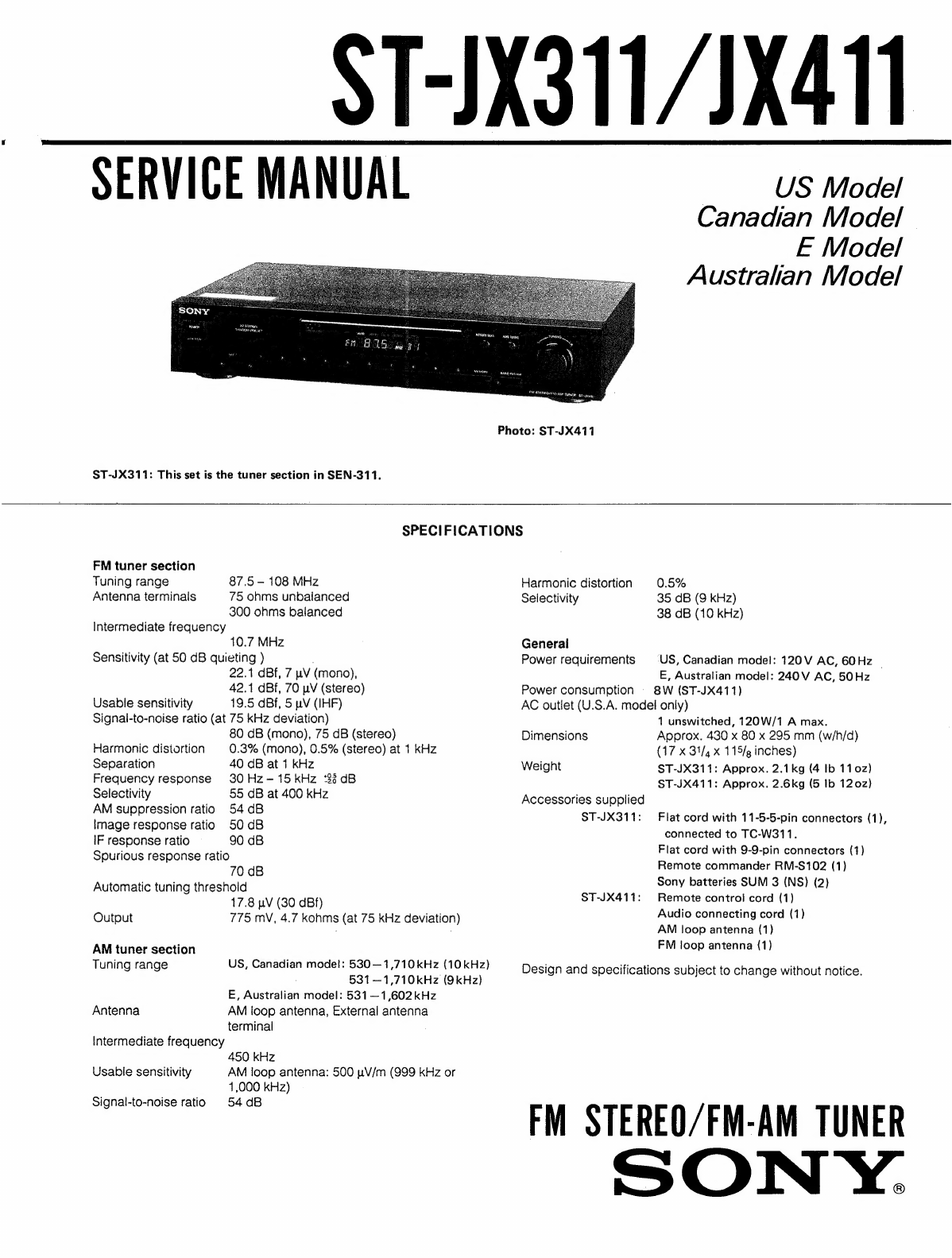
Sony ST-JX311 User manual
Other Sony Tuner manuals


Sony
Sony ST-S800ES User manual

Sony
Sony WRR-810A User manual

Sony
Sony ST-S500ES User manual

Sony
Sony R-D-S EON ST-SE700 User manual

Sony
Sony MB-8N Installation and operation manual

Sony
Sony HCD-D11 User manual

Sony
Sony ST-S770ES User manual

Sony
Sony XDR-Fl HD User manual

Sony
Sony Ipela NSR-S10 User manual

Sony
Sony MB-8N User manual


Popular Tuner manuals by other brands


MFJ
MFJ MFJ-928 instruction manual

NAD
NAD C 445 owner's manual

Sirius Satellite Radio
Sirius Satellite Radio SC-FM1 user guide

Antique Automobile Radio
Antique Automobile Radio 283501B Installation and operating instructions

Monacor
Monacor PA-1200R instruction manual

Technics
Technics ST-X301L Service manual