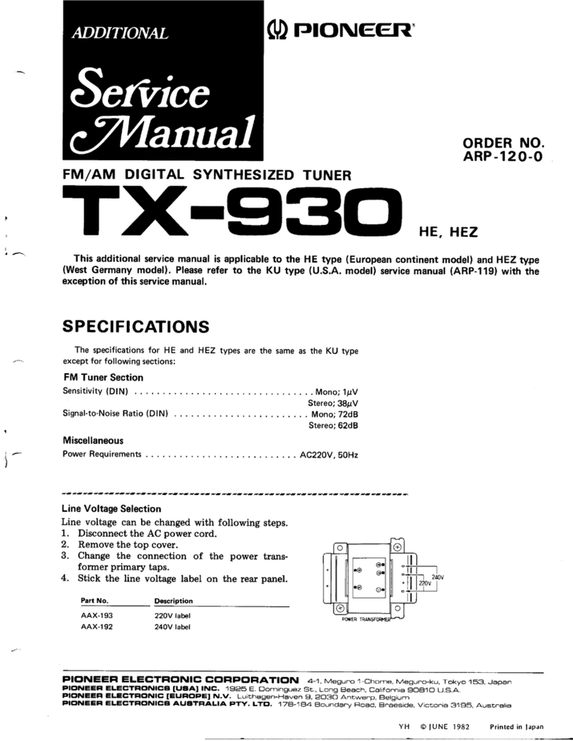
Pioneer TX-520 User manual

^{æffiHf.$WË#ffiffi,
STEREO
TUNER
o This
service
manual
is
applicableto the KUtype.
o Whenrepairing
theYP,S
andS/G
types,
please
see
paç 25.
o Ce
manuel
d'instruction
serefère
aumode
deréglage,enfrançais.
o Este
manualdeservicio
tratadelmétodo
deajusteescritoenespafrol.
1.
2.
3.
4.
5.
6.
7.
8.
9. ELECTRICALPARTS
LIST
10.
EXPLODEDVIEW
11.
PACKING
12.ADJUSTMENTS
nÉcuce
AJUSTE
ADDITIONAL
SERVICEMANUAL
(FOR
YP,SANDS/GTYPES)
ORDER
NO.
ART-653-O
MODELTX€20 COMES
IN FIVEVERSIONS
DTSTINGUISHED
ASFOLLOWS;
Type Voltage Remarks
KU AC120V
only U.S.A.
model
YP AC240V
only Australiamodel
s/G AC110V,
12OV,22OV
and
24OY
(Switchabte) U.S,
Military model
sACI10V.120V,
22OV
and24OV
(Switchabtel Generalexport model
ss AC110V, 12OV,22OVand 240V (Switchablel Soutch Africa model
CONTENTS
SPECIFICATIONS
FRONT
PANELFACILITIES
.
BLOCKDIAGRAM
CIRCUIT
DESCRIPTIONS
PARTSLOCATION
DIAL
CORDSTRINGING
P.C.
BOARDSCONNECTIONDIAGRAM
SCHEMATICDIAGRAM
2
3
4
4
5
6
7
I
11
13
14
15
18
21
25
PICINEEFI ELEGTFICINIC CCTFIPCIFIATICIN 4-1. Mesuno 1-chome. Mesuno-ku,
Tokyo 1s3. Jêp6n
U.a. FfCINIIE| IIICTF|CINIC3 CC'FIFC,F|AIIC'N €'5 Oxf o.d Odve. Moonechre. New Je€ey O7O74, U S A
Plcrl\lllFl ILCCTFICINIC (E!,FIC,PE, N.V. Lurchagen-H6ven 9, 2O3O AnEwerp, Elelgrum
FfCrTvllF| ILICTF|CINaCa ALTaTFIALIA PTY. LTEI. 17A-1e4 Boundê.v Floêd. Eln6esrde. VicEonr6 3195. Au6b6li6 =H@
MAR.
1981
Printed
in
Japan

3. BLOCK DIAGRAM
FI
tooo
AM TUNER
FM
IF AMP A OETECTOR I
75n
GilO
(
FT,|
MPXSTEREO OEIT|oOULAIOR
Ic(HAil56wl
INOICATORS
Ftl +B +--i- V.R.
+8
AM +B---:o I
4. CIRCUIT DESCRIPTIONS
FMTuner
The FM front end is comprised of a J-FET
(2SK168) single+tate RF amplifier, an NPN
transistor mixer, and an NPN transistor modified
Clapp local oscillator.
The IF stageconsists of 2 dualclement ceramic
filters, a single transistor amplifrer element, and an
IF system IC (PA3001-A) which incorporates
the IF limiter amplifier, FM detector, and the FM
muting circuit.
FM Multiplex Stereo
Decoder
The stereo decoder stage employs an FM MpX
IC (HA1156W-P), while the subcarrier signals
(frequencies above l9kHz) are removed by an
-18d8/oct. active filter consisting of a pNp
transistor. This active filter also sewes as an
amplifier for frequencies within its passband,
and eliminates crosstalk.
FM IF SYSTEM
Ic
(PA300r-a
)
AMTuner
This employs a 2-ganged tuning capacitor, a
dualclement ceramic filter, and an IC (HA119T)
consisting of a RF amplifier, mixer, 2-stage IF
amplifier, detector and AGC circuit.
Signal
Strength lndicator
The TX-520 signal strength meter is a b-point
LED display meter driven by the meter drive IC
(L81416). The signal meter drive signalsfrom
the FM and AM tuner sections are applied to a
set of 5 voltage comparators which are activated
according to the difference between the applied
signal level and the respective reference vottage
levels allotted to each comparator, resulting
in the LEDs(1-5) being
lighted.
METER DRIVE
IC
(
L81416
)
Fig.
4-1 Signal
indicator
circuit

2. FRONT PANEL FACILITIES
o POWERSWITCH
When
this switchisset
to the ON position,power is
sup-
plied
to thetuner's
maincircuits.
Theunit's
power
switch
isgeared
to selecting
thetransformer's
secondary
andso
even
at theSTAND'BY
position,
theunit'scircuitry
will
work as
long
asthe
power
cord
is
connected
to the
power
outlet.
Disconnect
the power cord from the poweroutlet when
you do not plan
to usethe
unitfor along
period
of time'
€) FUNCTION
SWITCH
When listening
to an FM broadcast
- Setthe function
switch
to theOUT (
r )position.
When listening
to an AM broadcast
- Set the function
switch
to thedepressed
( ^ )position.
@ FM MUTING
SWITCH
Whenselecting
an FM broadcasting
station,
this switch
removes
the irritating
noise
between
stations'
lt should
normally
be
inthe
ONPosition.
When
thesignal
is
weak
andthere
is
a great
deal
of noise
or distortion
with thisswitch
ON,making
it difficultto
hear,then it should
be pressed
to put it in the OFF
position (in this case
mono reproduction
is obtained)'
@rurutruc
KNoB
Turn
this
to select
abroadcasting
station
(FM
or AM)'
@ otnu
scALE
This indicates
the frequencY
(FMor
AMI'
upper
number
(88
- 108)
-
lower
number
(55
- 160)
-
@ otal PoINTER
This moves
right
or left when
thetuningknobis
turned.
Line it up with the frequency
of the station
you wantto
listen
to.
O stcruel lNDlcAToR
This
indicates
thestrength
of thesignal
from the (AM
or
FM) broadcasting
stationto which you are presently
listening.
The larger
the numberof the lamps
lit up,the
stronger
the signal
(a
strongsignal
indicates
that reception
conditions
areoptimum).
G) TUNEDINDICATOR
This lights
up whenan FM broadcasting
station
isbeing
received.
This lamp doesnot light up when an AM
broadcast
is
being
received'
@ STEREO
INDICATOR
This
lamp
lightsup automatically
when
an FM broadcast
isin stereo.
lt does
notlight
up
when
theFMMUTING
switch
issetto OFF.
@ FM T.TYPE
ANTENNA
This antenna permits FM broadcasts
to be heard until a
regular
FM antenna
isinstalled.
NOTE:
When the broadcasting
station is far away' or in case
of weak
signats
btockedby mountains,
it might not be possible
to receive,
FM broadcasts
with this
antenna'
ln such
a case'
pleaseinstall
anantenna
exclusivelY
for FM uæoutdoors'
of thebroadcasting
station
frequencY
ofFM
station
frequency
of AM
station

1.SPEC|FlcATloNs
FMTuner
Section
Usable
Sensitivity . . 10'8dBf
(1.9r..V)
5(HBQuietingSensitivitY
MONO ..17.3dBf(4.0sV)
STEBEO 39.2dBf
(50svl
Signal-to-Noise
Ratio
(at
65dBf)
MoNo " " 75d8
STEBEO ....70dB
Dislortion
(at
65dBf)
MONO .-'.1kHz;0.1o/o
STEREO ....1kH2;O.2o/o
Capture
Ratio . ldB
AlternateGhannel
Selectivity
(400kHz) .60d8
Stereo Separation
lkHz. .....40d8
Selestivity .....25d8
Signal
to Noise
Ratio . . .50d8
lmageResponse
Ratio . . .40d8
lFResponseRatio. ...70dB
Antenna ,.. Ferriteloopstickantenna
Audio Section
Output (
Level/lmpedance) 650mV/3.6kO
FM
(100%
MOD)
AM (30%
MOD) lSOmV
Frequency
Besponse
. .
Spurious
Response
Batio .30Hz
totstnzlo'f
oa
Miscellaneous
PowerRequirements .... AC120V,50/60H2
PowerConsumption ....llw
Dimensions ... 420(W)x
94(H)x254(D)mm
16-9/16(W)x 3-11116(H)
x 10(D)in
Weight
(Without
Package)
FurnishedParts 3.2k9
(6lb
13oz)
FM T-type
antenna
Operating
Instructions
NOTE:
Specifications and the design subiect to possiblemodifica-
tion without notice due to improvements.
lmageResponseRatio ...55d8
lF
ResponseRatio.. ...80d8
AM Suppression
Ratio . .55dB
MutingThreshold ...19.2d8f (5pV)
Antenna
lnput . . 3(X)ohmsbalanced,
75ohms
unbalanced
AM Tuner
Section
Sensitivity
IHF ferriteantenna 300frV/m
lHFexternalantenna. .....30pV

3
2
,r
()( T.tl,T
:?1,
iil-L+;l
iQr4 Qt2 QTQO 09 ,
HAl156W.P
T4 T2 1C4 VCITCi vRl
TC5VC3
\Æ2 rc2
,:* '" I]'Ki
HJ
[&ti,,,'
., .;
'- -1.r H l-a
9iç+d
ti R?6
3.46X
1? r
,.:F?ll4l(
)
-l
-
-
*3-rrr--
Ll "t'*
# **=
ffi ffi* Ëâ ffi
@ ffi fÈ, t'",,"
'cà ,,,1
.
"r€]",|Ê;f:Ë
r , Y#lu,T --i-- *Rfi,.-,,",^"
::l'i [:'na4pu- 33/50
''fJ.,fti Tc ] ' ,,1Ëlfff
ibJi ffi #
i '_b€lf,r".;,ld;
ff;* #
Èf - | | Jù*;";;;','J_hË;EE ili;
@ 's'T-ffi,'"':io
i i :t':"f-'il.;{îfl,ryF
#l , '!{:,,,,
PA3001-A
HAl 197 2SA726S
2s'c2575
I
E
3
2
1
7. P.C.BOARDS
CONNECTION
DIAGRAM
ATUNER Ass'y(cWt- | SZ)
Q4 Q5 02 Q3
ExternalAppearance
of Transistors
and lCs
2sKt6B 2sc461
2Sc53s
E
i "____,f--* i 0iz aEe j:
ï'ffiLJffi
'
-:
ll -,.",,.$j.'ilgji'
ffiÆiffi#':,.,ï*fu ri.,-
r;___-t I i I e ,,:7- 16i,o0K
at2 zsc461 ll , .--_ fir:T
. "..^'lffil.jfl"TE* ffi-g *tq"- + L+=j-s-
*4*l-.=*=*-#i,lo-.,:...-.,1.rcai**.{fi|.-,:*.-Æ

6
DIAL POINTER SWITCH Ass'Y
(cws-346)
LED Ass'y (GwX-634)
zscxt45A
Tl:POWER TRANSFORMER
r------\ Rtoo 2 2M.(t/2w)
LBl4t6
PL2
aV I OOmA
PLI
AVO3A
AC | 20V
5
4

5. PARTS LOCATION
Front
Panel
View
Front panel
assemblY
ANM-005 r
Rear
Panel
View
Strain relief
AEG76O
Terminal
(ANTEN
AKA.O14
TopView
Dial pointer assembly
AAF-I11
* * LamP with wires
AEL-l55
A * Power
transformer
ATT-790
A i* Pushswitch
(POWER)
ASG-s16
** l€mp
AEL-108
Switch
NOTES:
CTheAmarhfound'onsomecomponentpartsindicatestheimportanceofthe
safetyfactoroftnepart'Therefore,whenreplacing,besuretotnepartsofidentical
designntion.
oForyourPartsstochControl,thefætmovingitemsareindicatedwiththe
marhs ** and *
i7 cawsnALLY MovES FASTER
THAN *
This
clasification
snitt-UeTdiueted
byeach
distibutorbecarse
it depende
onmodel
number,
temperature,
humidity,
etc'
base
AEC-741
KNOb
(TUNING}
AAA.O71
Knob
(FUNCTION,
FM
MUTING}
AAD.268
Terminal
(AM
STEREOOUTI
AKB-O76
Strain reliel
AEC-327
ACpower
cord
ADG.Os2
ADE.O34
Tuning
shaft
assembly
AXA-292
* * Push
switch
(FUNCTION,
FM
MUTING)
ASG-261
LED assembly
cwx-638
Top
GWs346

Dial
Pointer
6. DIAL CORD
STRINGING
1. Removethe top cover and front panel'
2. Remove the tuning drum from the shaft of the
tuning caPacitor'
3. fie one end ot it'e cord to the stud A located
inside the tuning drum'
4. Rotate tfte tuinË-capacitor right,around until
-' ifr" ,otot bladesa"" tutty intermeshed'
5.
6;;;" thetunintdnrm
back:"IÎ,tÏ t^TT::
"' Jupu"itot shaft, Àaking sure-
that the secunng
t"i"* B facesdirectlY uPwar-d'
6. Pass
the cord o"i Utt""gtt the small opening in
the circumt"'""àt of lrre tuning drum (see
diagram), ""a tf'"tt take it over pulleys C' D
and E in that sequence'
z. friiJtrt" "o'a Jtà"ttd thetuningshaft 3 times'
8.Pass
it over
p"ff"V f' *ii.d il."t9lÎd thetuning
drum 2 times, iiJ littutty tie it to the spring
ttà.t C so
that it istensioned'
9. Tum the tuning shaft, and check that the cord
movessmoothly.
10. Cut off any excess
eord'
ii. T;-ù; tuning shaft counter'clockwise
asfar as
it will go'
12. Alig the dial p"i"t"" wrth the starting point
--' ;; A" dial scaie, and then passthe cord over
it.
13. Check that t'tre diat pointer is in line with the
- - starting point of the dial scale'
14. Finally appty ttr" locking paint to the cord
securing positions (stud A and spring hook G)
and the dial Pointer connecuon'

9. ELECTRICAL
PARTS LIST
NOlES;
o llhen ord,ering resisfors, first convert resistance ualuecinto code form asshown in
the following examples.
Ex. 1 Wen there are 2 effectiue digits (any digit apart from O),such æ 56O ohm
and 47h ohm (tolerance is shown by J=5%, and K=lO% ).
56Oa 56 x lol
57ka 47 x 103 561
. .. .. RD%PS
E[tE J
473.,.., RD%PS
EAAB
J
-
o.sa 0R5.. .... RN2H
@rE6 K
rsl 010
.. .... æsrP
@a@
K
Ex. 2 Wen there are 3 effectiue d,igits (tuch as in high precision metal film
resistots),
5.62ha 562x 10' 562r . .. . RN%SR
@6@ln
F
c The I mark found, on some component parts indicates the importance of the
safety factor of the part. Therefore, when replacing, be sure to use parts of
ide
ntical desi gnati
on.
o For your Parts Stoch Control, the fast mouing items are indicated with the
marhs ** and * .
** GENERALLY MOVES FASTER THAN *
This classification shall be adjwted by each distibutor because it depends on
model number, temperature, humidity, etc.
Miscellaneous
Parts
I
Mark Part No, Symbol & Description Part No. Symbol & Description
A
3
A * ATT-790
*i AEL-108
** AEL-I55
a ACN{29
ADG452
ADE-O34
GWE-l
52
GWS-346
GWX-638
AKB076
Tuner
Assembly
(GWE-I
52)
CAPACITORS
Mark Part No.
T1 Power transformer
PLI Lamp assembly
PLz Lamp with wires
R100 Carboncomposition
resistor (2.2M1%Vll
AC power cord
Output cords with phono plugs
Tuner assembly
Switch assembly
LED assembly
Terminal
(AM STEREO OUTI
Symbol & Description
c37,C39
c30,c:]1
g2,c5, cl 1, C13,eA7,C52.
CU,
c56,C69
cl4, Cl5,C17,
C18,C20,C22,
C23,
c26,C29,C49,C50,C71
c24
c51,C57,C68
c58
æ2
c33
c34
c16,æ5,U3,U4
c27,C60,e,61
c19
u6,62
c25
c55
c63
c28
cæ
cæ,67
c65
u5
c36,C70
CKDYB
222K50
CKDYX273M25
CKDYF
1032
50
CKDYF4732
50
CKDYX473M
25
CKDYF223250
cosA 331K 50
cosA 511J
50
CEA
R33M
50L
CEA
OlOMsOL
CEA
R47M
50L
CEA
OlOM
50L
CEA
2R2M
50L
CEA
lOOM
50L
CEA4TOM
1OL
CEA4R7M
35L
CEA
101M
25L
CEA221
M16L
CEA221M25L
CEA
471M
16L
CEA
471
M25L
CEA3R3M
50L
CEA
1O1M
16L
-
ACK-OI2
ACM-006
ccDUJ
O90D50
CGB
R47K
5OO
ccDzM 050Ds0
ccDSL 060D50
ccDcH 080D50
ccDcH 1
50J
50
ccDRH 150J
50
ccDUJ 150JsO
ccDcH 330Js0
ccDsl 101J
50
Tuning capacitor
Ceramictrimmer
VC
TCXI
c1
c10
c59
u
c7
c9
c6
c3
c8
c12
ccDsL 221J50 c21
CKDYB561K
50 C38,C40
CKDYB
102K
50 C53
CKDYB122K
û U8
CKDYB182K
50 CA1
,CA2
-11

(
rr AcPo7g
RD%PM
trBtrJ
RNz4PO
trODDF
SEMICONDUCTORS
Mark Pan No.
VRI Semifixed
(5k-B)
Rl-R4, R6-R25, R27-R34,
R36-R67, R74-R78, R80-R87
R26,R35
RESISTORS
NOTE:When ordering resisfons,
conuert the resistance
value
into codeform, and thenrewrite the portno. as
before.
Mark Pan No. Symbol & D6cription
OTHERS
Mark PartNo. Symbol& Dercription
* * ASG-261 Push
switch
(FUNCTION,FM
MUTING)
AKA-O14 Terminal4-p (ANTENNAI
PMZ3OPOGOFMC Screw3X 6
VBZ3OP100FZK Screw3
X 1O
SwitchAssembly
(GWS-346)
Mark PartNo. Symbol& Dcc.iption
A ** 496€,15 Push
switch
(POWERI
LEDAssembly
(GWX-638)
NOTE:When ordeing resrstors, conuert the resistance ualue
into code form, and then rewite the part no. as before.
Mark PartNo. Symbol& Dæcription
Symbol & D$cription
** 2SK168
** 2SC535
** 2SC461
** PA3001-A
** HAt156Wf
** 25A7265
** (2SA7501
** HAl197
A ** zsoego
A ** (zsogrs,
** L81416
** 2SC945A
** (2SC257st
* 1082
r (srB0102l
* KZL130
* 152076
* (1S15551
* 1152473''
COILS,
FILTERS
Mark Part ltlo.
o1
a2
03,o4,o12
o5
o6
07,o8
o9
010
013
011,O14
01
,o2
D3
D13,Dl4
RDy.PM
trtrtrJ
* AEL-337
* AEL334
R68-R73
D4-D9 LED(Greenl
D10 LED
(Red)
I
I
A
^
Symbol& Dæcrlption
ATEO49
AT8.()66
ATEOOS
124428
AT8623
ATFO53
ATF-I21
ATFO38
T2 FM
det.
transformer
T3 AMosc.coil
T4 FM lF transformer
L6 RF
chokecoil
L7 Bar-antenna
assembly
Fl ,F2 FM
ceramic
filter
F3 AMceramic
filter
F4 AM lFfilter
'1
2

o
12. ADJUSTMENTS
12.1 FMTUNER
SECTION
Connect the FM signal generator (FM SG) to the FM antenna 300O terminal through a 300O dummy
anænna.
Setthe FUNCTION switch to the FM position, the MUTING switch to the OFF position.
The tuning coil in the FM front end dosenot havean adjusting core.
Consequently, tracking adjustments at 90MHz are performed by regulating the gap between rotor and
stator of the tuning capacitors
(VC1, VC2 and VC3).
The expression "adjust VC (VCl, VCz and VC3)" found in the text meansthat the two outer rotor
blades of each of ttrese tuning capacitors are be extended outwards with spatula (Part No. GGK-066)
asshownin Fig. 121.
a
a
rFÈ
-Multiplex Decoder
Section
o Connect the FM multiplex stereo signal generator (FM MPX SG) to the FM SG extemal modulation
terminal.
o Setthe output of the FM SGto 98MHz and level to 86dB (with modulation mode setto EXTERNAL)
andtune the TX-520 unit to that frequency (98MHz).
o Setthe MUTING switch to the ON position.
Step FM SG (400H2,t 75kHz deviation) Position of
dial pointer Adiustment
point Adju Jtmont 3pecifacetion
Frequency Level
1ldle 106MHz T2-N OV DC between terminal no. 8 and no.9.
2106MHz
90MHz
60 to 80dB
60to 80dB
106MHz
90MHz
TC3
vc3 Adirrct rrntil f)C mltaoa hetweên ferminâl no 35 and oround
3
4Repeatsteps to 3 above. ismaximum, and 0V DC betvveenterminal no. 8 and no. 9.
5106MHz
9OMHz
20dB
20dB
106MHz
90MHz
TCl ,TC2
vcl .vc2
6
7Repeat steps to 6 until maximlrm
sensitivity isattained.
I98MHz 66dB 98MHz T4 Adiust until DC voltagebetween terminal no. 35 and ground
is
maximum.
Ildle 98MHz T2.N OV DC betuæen
terminal no. I and no.9.
10 98MHz 66dB 98MHz T2-D Adjust until distortionat OUTPUT terminalisminimum.
11 Repeat
steps9 to 10 until both specificationsare
correct.
12 Set
the MUTING switchto the ON position.
13 98MHz Variable 98MHz Check that the muting circuit is not functioning at above 26d8.
lf not, remove
822.
Step FM MPX SG Adjustment
poant Adiustmont spæification
1ldle (nomodulationl VRl Adiust signalat terminalno. 10 to lgkHz (within tlOoHz).
2fvlain
(1kHz, L+R, r67.5kHz deviation)
Pilot (19kHz, 7.5kHzdeviation) T4
within tgo" Adiust until distortion
at OUTPUT terminalisminimum.
1-

o
I
o
Fig.12-1 Adjustment
of tuningcapacitor
R224
no.
10-{
B- no.9
@
I
VR1
Bar-antennacoil
vc2
B
-@ q
T3
Fig.12-2 Adiustment
points
and
measuring
points
&- no.35
Tuner
assembly

32
1
8. SCHEMATIC DIAGRAM
TUNERAss'y GwE
-152
Qt 2SK|6A Q3 2SC461 Q2 2SC535
O1-3 FM
FRON'-END
L6 22lH
Q4 2SC461 Q5 PA3OO1
-A
FIVI
IF AMP Fill IF AMP
& O
L3 L4 VC2 TCz
L2 VCr TCI
t-
FMËiPI
LzsnL
UNBAL
GND
AM c2
-r
vc3
Qtz 25C461
AI!1
STEREO
OUl BUFFE
-Lctr
Tool
RB Ica
27r T rsP
---lc
q9 HAr197
ÀM
IUNERIC
Qlo 2sD880
REGULAlO
R
l- c5
Taol
AC
POWER
COÂD
a0G
-o52
R2 tao
R9 tgo
T'ool
R5847 Qro
R64
560
TOOI
m
t_ _,
D2OE?
SWITCHAss'y GWS-346
Fr-- ,A
c65
470,/
È25
R60
+ 47o
c64
2?O/
?5 too/
.25
o3
KZLî3O
Rtoo
2,2M
|/2w)
(
oraL
P0r{l€R
PLz
sl
POWE
R
asG-5r6
8V IOOnA
AEL-I55
PL
i
8V O 3A
AEL-IO8
ac r2ov
Â\-JF 60 Hr
13
2
;c32 r----ql sZ-r-3
lSroD| .lI
##-FM
vRl
I
vco AoJ
acP-o79
c55
35
c45
33/
50
Q6 HArrS6w-
P
I\4PX IC
", a c56
D2 470/
(
POWER

65
4
' t/30
L C20
Tooez
#
c43
o.47
/50
R27
47r cr9
zz,/so
NOTE:
The indicated, semiconductors are representative oneg
only. Other alternatiue semiconductors may be used and
are listed in the parts list.
LI
OUTPUT
I
R_
Fso'-l
AT FM
roo I Mo0
1-RESISTORS:
fndic.ted in a. %W, !5% tolerarce uô16 orhêniisnoted k : kQ,
M: Mo. (Fl : rl%, (Gl : r2%,
(Kl I r1096, (drrll:,2O% toleræ
2-
CAPACITORST
Indicated in capacity kF)/voltage (v) urilessotheMise notedp : pF
lhdication without voltage is 50V except elælrolytic capacitor,
3. VOLTAGE
ï*l I] : DC voltage (V) at no input signal
Il--É-Vl:
Signal
votraseatFM4OOHz75kHzDEV
4-OTHERS:
@ :Adjusting poinl
The 2\ mark found on rcme codponent pans indicates the im'
poftance ol the glety tactor of the part. Therefore. when replacrng,
be sre to use
parts
of idenlicai
dBignation
This isthe basic
shemalic diagram,
bul the aclual crrcuit may vary
due to improvemenls
in desiqn
SWITCHES:
SI : POWER ON - STANO-8Y
S2-I: FUNCTION FM - AM
S2-2: FM MUTING ON - OFF
The unde.lined indicatesthe switch position
-
-
-
ISTEREO
)
AEL-
337
AEL
-334
D Ass'y GWX-638
6
5
4
LEVELSET
ITVERTER
,""i,f
}"":,èif,J|:* !
Îl: Q?,8 asa?z6s I sa-"
rurc'm
R40 azr R4r
tO*
er1,
14
zsce45a 14
'
I Til'-*:*'^ 1lâ3-
.!'c lJ\- + +;'--"*
{3E
rUNED
-CN )
1234567
q13 LBt416
SIGNAL INDICAIOR
DRIVER
141312iltOIA

10.
EXPLODED
VIEW
D
I

11. PACKING
Mark No. Part No.
1.
2.
3.
4.
AHA-29O
ARB4O3
ADH.OO4
AHD899
Side
pad
Operating
instructions
T-type FMantenna
Packing
case
@.@-æ@@%xæ',wé@*
Parts
List
of Exploded
View NOTES:
c Parts without part number cannot besupplied,
c The $, marh found on some component parts indicates the importance of the
safety factor of the part. Therefore, when replacing, be sure to use parts of identical
designation.
c For your Parts stoch control, the fast mouing items ore indicated with the
marks ** and *
** GENERALLY MOVES FASTER THAN *
This classifîcation shall be adjusted by each distributor becauseit depends on model
numbe
r, tempemture, humid ity, e
tc.
Description Mark No. Part No.
No. Pen No. Description
Description
1. ANE-291
2. FBT4OPOSOFZK
3. VB230P100FzK
4. AEL-l08
5. cws-346
6. vBz30P080FMC
7- PMZ30P060FMC
8. AAD-264
9. ANM-O05
10. wA92F140U050
11. NKgOFUC
12. AEG741
13. AAA-O71
14. ADG-052
15. AEG327
16. ATT-790
17. ABA-252
18. AEL-l55
19. AAF-I11
20. AAD-268
21. PMZ30P40FZB
22. GWX.638
23. AXA-292
24. A8A-246
25. AEC678
Top cover
Screw4 X 8
Screw3
X 10
Lamp assembly
Switch assembly
Screw3 X I
Screw3 X 6
Knob (POWER)
Front panel
assembly
Flat rarasher
Nut M9
Knob base
Knob (TUNING)
AC power cord
Strain
relief
Power
transformer (1
20V)
Screw3
X 8
Lamp with wires
Dial pointer assembly
Knob (FM MUTING,
FUNCTION}
Screw3 X 4
LED assembly
Tuningshaft
assembly
Screw3
X 12
Nylon rivet
26.
27.
2A.
29.
30.
31.
32.
101.
102.
103.
104.
105.
106.
107.
108.
1
09.
110.
111.
112.
113.
1
14.
115.
116.
117.
ADE-034
AEC-760
AKB.O76
GWE-152
AEC-609
Output cords
Strain relief
Terminal (AM STEREOOUT)
Tunerassembly
Foot assembly
Terminal strip 2-P
Side
frame L
Side
cover
Flexible
joint
Dial scale
board
Sub-panel
Pulleyassembly
Smoother
Plate
Serial
numberplate
Rear
panel
Guide
arm
Tuningdrum
Holder
Pulleyassembly
Sideframe R
Bottom plate
**
A
A*
**

12.2AM
TUNERSECTION
o Connect
the AM signal
generator(AM SG)
to the AM ANTENNA terminalthrougha 10kA resistor.
o Set
theFUNCTION
switchto theAM position.
*Slide the bar-antenna
coil along the core.
Stap AM SG (4filHz, 3O%modulationl Position of
dial pointer Adiustment
point Adjustm€nt spocification
Frequency Level
1400kHz 100dB 1400kHz TC5 Adiust until demodulated
signal
at OUTPUT terminalis
maximum.
z600kHz 100dB 600kHz T3
3Setthe AM SG to 30dB output level,repeatstepsI to 2 above.
41400kHz 50dB 1
400kHz TA Adjust until demodulated
signalat OUTPUT terminal is
maxrmum.
5600kHz sodB 600kHz Bartntenna*
6Repeatsteps
4 to 5 until maximum sensitivityisattained.
7100OkHz 50dB 1
000kHz F4 Adjust until maximum sensitivity
isattained.

12. REGLAGE
I2.I SECTION TUNER FM
o Raccorder le générateur de signaux FM (FM SG) à la borne de I'antenne FM 300 S) au moyen d'une
antenne
fictive de 300 O.
o Amener I'interrupteur FUNCTION en position FM et I'intermpteur MUTING en position OFF.
o La bobine d'accord à I'entrée FM n'est pas pounme de bobine de réglage.
Par conséquent, les aligne-
ments à 90 MHz sont exécutés an réglant I'espaceentre le rotor et le stator descondensateurs
d'accord
(VC1, YC2et VC3). L'expression"Régler VC (VCl, YQ2 et VCg)" dansle texte signifie que les deux
palettes du rotor exterieur de chacun de ces deux condensateurs d'accord doivent être toumées vers
I'extérieur aumoyen d'une spatule (pièce no GGK-066), comme indiqué zur la figure 12-1.
Section décodeur multiplex
o Raccorder le générateurde signaux stéréo multiplex FM à la borne de modulation externe FM SG.
o Régler la valeur de sortie du FM SG à 98 MHz, le nivau à 86 dB (la commande de modulation étant
surEXTERNAL) et leTX-520 àla mêmefréquence
(98 MHz).
o Amener I'intermpteur MUTING en position ON.
a
I
a
Pæ
FMSG
(éOOHz,
t 75kHz d6rivol Position de
l'indicateur Point de
réglage Sp6cif ication de r6Slago
Fr6guence Niveau
1Déwatté 106MHz T2.N OVCCentre
laborne
no
8 et no9.
2106MHz 60
à80d8 106
MHz TC3
390
MHz 60à80d8 90
MHz vc3
4Répéter
le
pæ2 et 3 Régler
jusqu? cequelevoltæe CC
entrelaborneno35 at la
miseàterreest
aumaximumet 0V CCentrela bornenoI et
no9.
5106
MHz 20dB 106
MHz TCl, TC2
690MHz 20 dB 90 MHz vc1.
vc2
7Répéter les
pas5 et 6 jusqu'à ce que lasensibilité maximum estatteinte.
I98 MHz 66dB 98 MHz T4 Régler
jusqu? ceque le voltaç CCentre la borne no 35 et la
miseà terre est au maximum.
9Déwatté 98 MHz T2.N 0V CCentre la borne no I et no 9,
10 98MHz 66dB 98 MHz T2-O Régler
jusqu'à ceque la distortion â la borne OUTPUT est
minimum.
11 Répéter les
pæ 9 et 1O
jusqu'à l'obtention des
valeurc
@rrectes.
12 Amener
l'interrupEurMUTING
en
position
ON.
13 98 MHz Variable 98MHz Contrôler
sitecircuit
de
silencieuxfonctionne
audessus
de26dB.Sicela
n'est
pas
lecæ,
enleverR22.
Pas FM MPX SG Point de rQllaç Sp6cification de réglaç
1Déwatté (pæ de modulation) VR1 Réglerle signalà la borne no 10à 19 kHz (entrer 100 Hzl
2
Principal
(1 kHz, L+R, i 67,5 kHz déviationl
Pilote
(19 kHz, t7,5 kHz déviation)
T4
entre t gO" Réglerjusqu'à ce que la distortion à la borne OUTPUT est
mtntmum.

12. AJUSTE
I2.1 SECCION DEL SINTONIZADOB DE FM
o Conectar el generador de sef,ales
de FM (FM SG) al terrninal de 300 ohmios de la antena de FM a través
de una antenaficticia de 300 ohmios.
o Poner el selector de funciôn (FUNCTION) en la posiciôn FM y el intermptor de silenciamiento
(MUTING) enla posiciônOFF.
o La bobina de sintonizaeiôn de la secciôn de entrada de FM no estâprovista de nûcleo de ajuste. Con-
secuentemente, los ajustesde seguimiento a g0 MHz sellevan a cabo regulando el entrehierros entre el
rotor y el estator de los capacitoresde sintonizaciôn (VC1
, VC2 y VC3). La expresiôn"ajustar los VC
(VC1, YC2 y VC3)" que seencuentra en el texto significa que lasdos paletasdel rotor exterior de cada
uno de estos capacitores tienen que extenderse hacia afuera con la espâtula (parte no. GGK-066) como
semuestra en la figura 12-1.
Secciôndel decodificador de multiplex
o Conectar el generador de sefralesestereofônicasde multiplex de FM (FM MPX SG) atterminal de modu-
laciôn exterior del FM SG.
o Ajustar la salida del FM SG a 98 MHz y el nivel a 86 dB (con el modo de modulaciôn ajustado a EX-
TERNAL) y sintonizarelTX-520 aesta
frecuencia
(98 MHz).
r Poner el interruptor de silenciamiento (MI-ITING) en la posiciôn ON.
Paso
FMSG
(4(X)
Hz,dewiaci6n
de
t 75kHzl Posiciôndel
indicador del
cuadrante
Puntode
âiust€ Especificaci6n del aiuste
Frecuencia Nivel
1Libre 106MHz T2.N 0VCCentre
el
terminalno,8
y elno.9.
2106
MHz 6Oa80dB 106MHz TC3
Alustar hasta
que la tensiônde CCentre
el terminalno.35 y
masa seael mâximo, y 0V CC entre el terminal no. 8 y el
no. 9.
39O
MHz 60a80dB 90 MHz vc3
4Repetir lospasos
2 y 3 de arriba
5106MHz 20dB lOGMHz TC1,TC2
690
MHz 20
dB 90 MHz vcl,vc2
7Repetir lospasos
5 y 6 hasta
que æ consigala méxima sensibilidad.
898MHz 66
dB 98 MHz T4 Ajustar
hasta
que
latensiôndeCC
entreelterminalno.35 y
masasea
elméximo.
ILibæ 98 MHz T2-N OV CCentre el terminal no. I y el no.9.
10 98MHz 66
dB 98MHz T2-D Alustar hasta
que la distorsi6n en el terminal de salida (OUT-
PUT) sea
la
minima.
11 Repetir lospasos
9 y 10 hasta
que ambæ especificaciones
sean
correctas.
12 Ponerel interruptor de silenciamiento (MUTING) en la posici6n ON.
13 98 MHz Variable 98 MHz Comprobar que el circuito de silenciamiento no esté
funcionando por encima
de 26 dB. Si no es asi,extraer R22.
Paso FM MPX SG Punto d€ aiuste Espæificaciôn del aiuste
1Libre (sin
modulaciôn) VRl Ajustar la seffal en el terminal no. 1Oa 19 kHz (dentro
de t 100
Hz).
2
Principal
(1 kHz, lzq. + Der., t 67,5 kHz de desviaci6nl
Piloto
(19kHz, x 7,5 k{z dedesviaciôn)
T4
dentro
de
t 90" Aiustar hasta
que la distorsi6n en el terminal de salida(OUT-
PUT) sea
lamfnima.

(GGK-066)
F
T3
Espâtula
Fig.12-1 Ajustecapacidaddesintonizaciôn
?
vc2
B
-@
f- no.35
Fis. 12-2 Puntosdeajuste
y demedici6n
R22-4
6-no.8
no.10
-f
Conjunto
delsintonizador
6-no.9
P
VRl
Paletadelrotor
X
X
Bobina
delaantena
debarra
22
Table of contents
Other Pioneer Tuner manuals

Pioneer
Pioneer TX-9100 KUW User manual

Pioneer
Pioneer SH-DT510 User manual

Pioneer
Pioneer FH-P5000MP User manual

Pioneer
Pioneer F-91 User manual

Pioneer
Pioneer XV-DV1000 User manual

Pioneer
Pioneer TS4 User manual

Pioneer
Pioneer F-551L User manual

Pioneer
Pioneer GEX-M7027XMZH/XN/UC User manual

Pioneer
Pioneer F-90 User manual

Pioneer
Pioneer TX-220Z User manual

Pioneer
Pioneer XC-F10 User manual

Pioneer
Pioneer XV-DV940 User manual

Pioneer
Pioneer GEX-P700DAB User manual

Pioneer
Pioneer F-757 User manual

Pioneer
Pioneer XC-IS22CD User manual

Pioneer
Pioneer XV-DV88 User manual

Pioneer
Pioneer GEX-P910XM User manual

Pioneer
Pioneer GEX-FM903XM User manual
Pioneer
Pioneer TX-610 User manual

Pioneer
Pioneer F-Z93L User manual