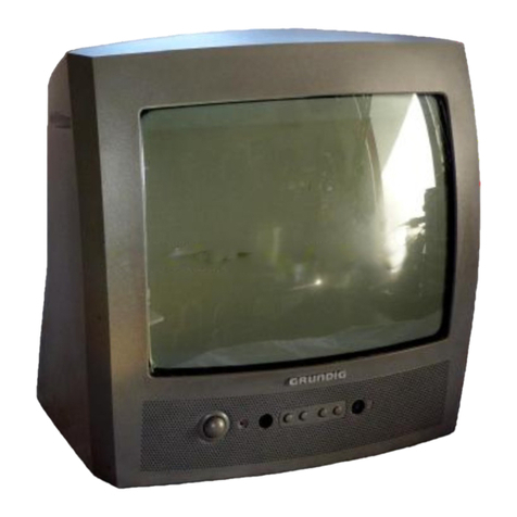
GRUNDIG Service Chassis TK
1 - 2
Table of Contents Page
General Section .................................. 1-3…1-38
General Notes ...............................................................................1-3
Special Functions ..........................................................................1-3
Product and Display Variants.........................................................1-4
Technical Data...............................................................................1-5
Operating Hints............................................................................1-23
Service and Special Functions ....................................................1-38
Layout of the PCBs
and Circuit Diagrams ......................... 2-1…2-36
Chassis Board VVK190R-2 ...........................................................2-1
– Block Circuit Diagram ................................................................2-9
– Power Supply...........................................................................2-10
– USB ........................................................................................2-11
– LAN..........................................................................................2-11
– HDMI........................................................................................2-12
– SCART, VGA, CV, YUV ............................................................2-13
– Tuner........................................................................................2-14
– DVB-T2 ....................................................................................2-15
– PCMCIA Interface....................................................................2-15
– DVB-S......................................................................................2-16
– Scaler.......................................................................................2-17
– Scaler-RAM .............................................................................2-19
– FRC .........................................................................................2-20
– FRC-RAM ................................................................................2-21
– LVDS........................................................................................2-22
– Amplifier...................................................................................2-23
Video Board Y3N192-3................................................................2-24
– Overview..................................................................................2-27
– Power Supply...........................................................................2-27
– Control IO ................................................................................2-29
– Processor.................................................................................2-29
– Memory/Config ........................................................................2-31
– SPI Interface............................................................................2-31
– LVDS........................................................................................2-32
Power Supply DPS-214CP..........................................................2-33
IR / LED Board ............................................................................2-36
Keyboard .....................................................................................2-36
Emitter Board...............................................................................2-36
Spare Parts Lists .................................. 3-1…3-5
Inhaltsverzeichnis Seite
Allgemeiner Teil .................................. 1-3…1-38
Allgemeine Hinweise .....................................................................1-3
Spezial-Funktionen........................................................................1-3
Geräte- und Display-Varianten ......................................................1-4
Technische Daten..........................................................................1-5
Bedienhinweise .............................................................................1-9
Service- und Sonderfunktionen ...................................................1-38
Platinenabbildungen
und Schaltpläne.................................. 2-1…2-36
Chassisplatte VVK190R-2 .............................................................2-1
– Blockschaltplan..........................................................................2-9
– Netzteil.....................................................................................2-10
– USB .........................................................................................2-11
– LAN..........................................................................................2-11
– HDMI........................................................................................2-12
– SCART, VGA, CV, YUV ............................................................2-13
– Tuner........................................................................................2-14
– DVB-T2 ....................................................................................2-15
– PCMCIA-Interface....................................................................2-15
– DVB-S......................................................................................2-16
– Scaler.......................................................................................2-17
– Scaler-RAM .............................................................................2-19
– FRC .........................................................................................2-20
– FRC-RAM ................................................................................2-21
– LVDS........................................................................................2-22
– Verstärker.................................................................................2-23
Videoplatte Y3N192-3..................................................................2-24
– Übersicht..................................................................................2-27
– Netzteil.....................................................................................2-27
– Control IO ................................................................................2-29
– Prozessor.................................................................................2-29
– Memory/Config ........................................................................2-31
– SPI-Interface............................................................................2-31
– LVDS........................................................................................2-32
Netzteil DPS-214CP....................................................................2-33
IR-/LED-Platte .............................................................................2-36
Keyboard .....................................................................................2-36
Emitter-Platte...............................................................................2-36
Ersatzteillisten ...................................... 3-1…3-5
Es gelten die Vorschriften und Sicherheitshinweise
gemäß dem Service Manual "Sicherheit", Material-
nummer 720108000001, sowie zusätzlich die even-
tuellabweichenden, landesspezifischenVorschriften!
Theregulationsandsafetyinstructions shall be valid
as provided by the "Safety" Service Manual, part
number 720108000001, as well as the respective
national deviations.


