Gruner F5J User manual

Introduction F5J
Assembly Manual
Original work in German by GRÜNER CNC Service, all rights reserved 20 5.
This version is published with the expressed permission of GRÜNER CNC Service.
Download the original document herewith full illustrations.
Translation to English by the following contributors:
●Fabien Gagné (FabFlight), Canada
●Christopher Kerrigan (Cricklewood), Canada
●Dario Ernst (NebuK), Karlsruhe, Germany
●Anthony Eden (aerotony), Australia
Grüner can not be held liable for consequential damages that may arise during the operation
of products from our product range.
Observe all notes intended for use (addendum).
No liability for misprints.
The reproduction of texts and text extracts, drawings and pictures is only allowed with our
express written permission.

Building instructions
Thank you for choosing a quality product MADE IN GERMANY.
Please read these building instructions and suggestions prior to construction, then carefully
proceed with the step by step construction.
PRESENTATION OF THE MODEL
The wings are constructed in three sections with carbon tube spars.
The wing joiners are built into the spars.
The wing profile used is the AG35.
The fuselage sides are reinforced with braces and stiffeners.
Wing ribs are precut to accept the carbon spars.
The tail feathers are builtup from trussed balsa parts.
The system is designed to use ORACOVER for the wings and fuselage, and ORALIGHT2 for the
tail feathers.
Due to the long nose and lightweight drive components, balancing the tail is as easy as possible.
Specific glue icons are shown in the relevant sections of the building instructions (NOTE: In this
English translation, the type of glue is specified between parentheses instead). For superglues
we recommend using normal cyanoacrylate (CA) and thick cyanoacrylate (thick CA, with a
slower set time).
TOOLS AND ADHESIVES
●Modelling knife, small balsa plane, sanding paper 00 and 80 grit, small round file, small
drill and Ø2.0 and 5.0 mm bits, fine metal saw, soldering iron, covering iron.
●Thin CA (ZAP)
●Thick CA (SLOZAP)
●5 minutes twocomponents epoxy (ex. UHU plus Schnellfest)
●90 minutes twocomponents epoxy (ex. UHU Plus Endfest)
DRIVE
Motor: (Premium) Hacker A2022L evo, (Standard) Roxxy 2834/ 2
Battery: 3S 300mAh, 0 g
Propeller: x6 CAM Carbon foldingprop
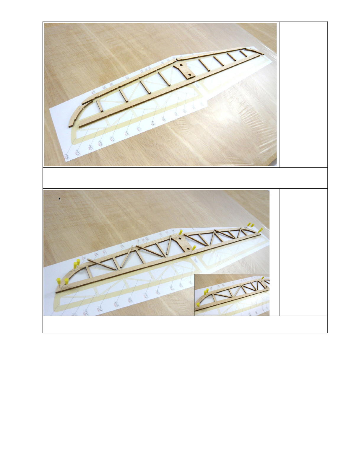
Sheet 72.08
Parts H H8
●Cut out the plan and cover with transparent film (cling wrap film or polyethylene).
●Glue together the tailplane parts H to H8 (thick CA).
2
Sheet 72.08
Parts H9-
H 2
●Check the fit of diagonal braces H9 to H 2 and glue into place without warping theframe
(thick CA).

3
Sheet 72. 3
Part H28
NOTE:This step is only required if building a removable elevator.
●Glue ply pieces H28 in the holes of the centrepiece H3(thick CA).
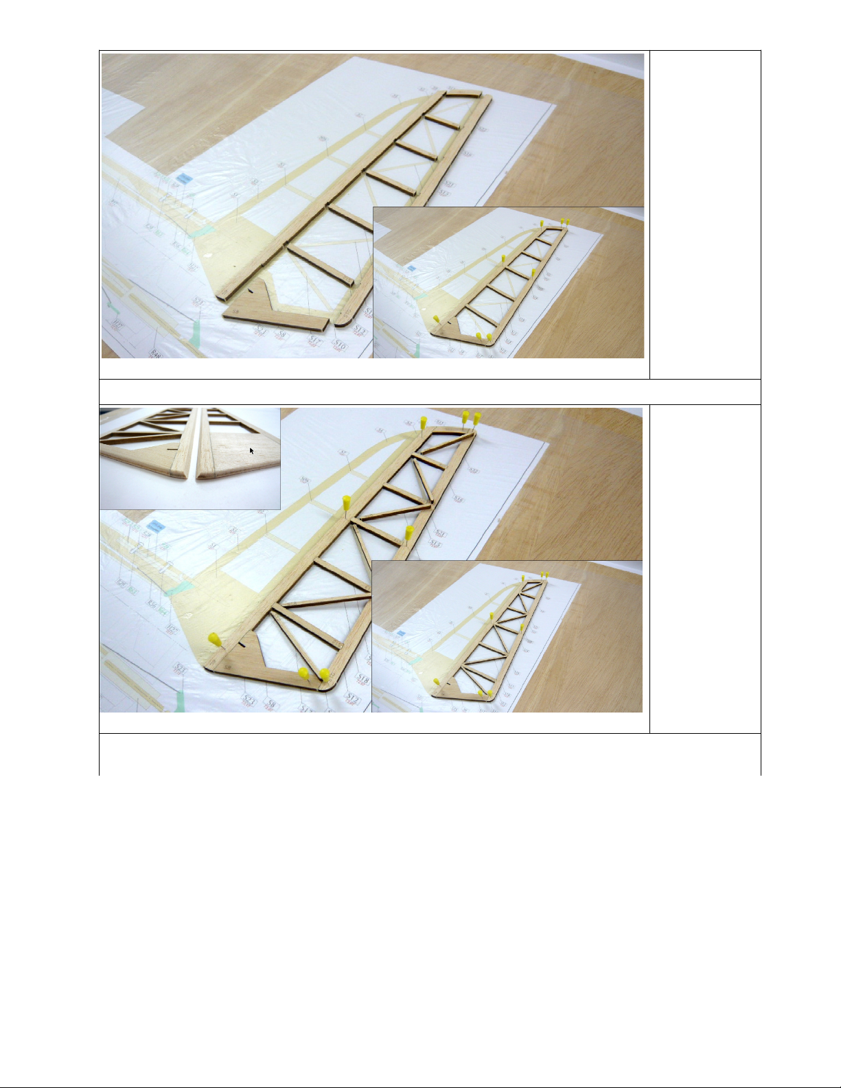
4
Sheet 72.08
Parts H 3-
H25
●Glue the elevator parts H 3H20 (thick CA).
●Check fit then glue the diagonal braces H2 to H25 without warping the frame(thick CA).

5
Sheet 72. 3
Part H26
●Figure . Glue together (stack) the two plywood elevator connectors H28(thick CA).
●Figure 2 and 3. Glue the connectors to the centre of the elevator(thick CA).
●Figure 4. Sand the tailplane and elevator according to thesections shown on the plan.
6
Sheet 72.07
Parts S -S7
●Glue the rudder parts S to S7(thick CA).

7
Sheet 72.07
Parts S8-
S 6
●Glue the rudder parts S8 to S 6 (thick CA).
8
Sheet 72.07
Parts S 7-
S22
●Check fit then glue the diagonal braces S 7 to S22 without warping the frame(thick CA).
●Sand the rudder to the sections shown on the plan.
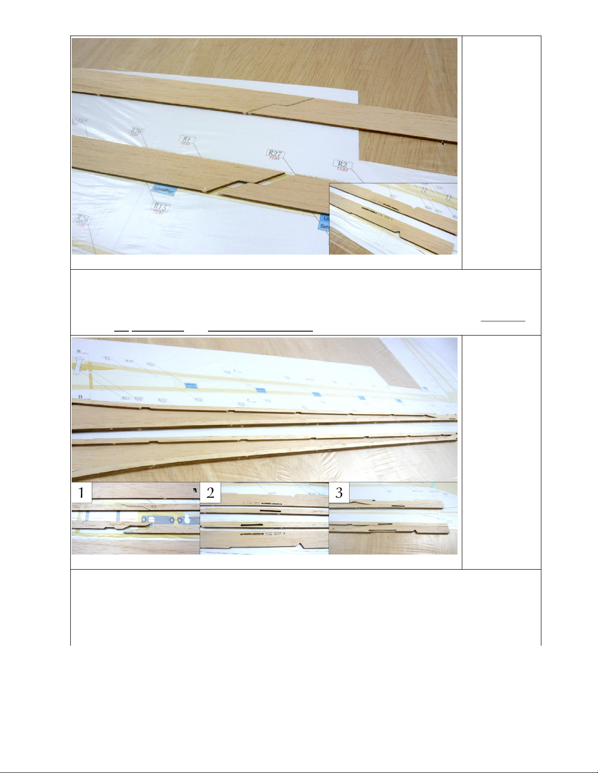
9
Sheet 72.02
Parts R ,R2
NOTE:In the following phases be sure to make one lefthanded and one righthanded fuselage
side.
●Glue the front and rear side portion of the fuselage walls R and R2 (thick CA).
●Cut out/file out the slots for the pushrod sleeves in the lefthand fuselage side infront of
the drilled hole,and behind the drilled holein the righthand fuselage side.
0
Sheet 72.05
Parts R3,R5
NOTE:Build experience from the EN translators suggests to perform the following three
steps in reverse order.
●Glue together the lower fuselage doubler parts R3 (front) and R4 (rear)(thick CA).
●Glue the lower fuselage doublers R3/R4 flush with the fuselage side (thick CA). Beware
of the pushrod hole position.
●Glue the upper fuselage doubler R5 flush with the fuselage edge(thick CA).

Sheet 72. 4
Parts R6,R7
●Glue the wingbed doubler R6 and front fuselage doubler R7 flush with the fuselage edge
(thick CA).
2
Sheet 72.05
Parts R8-
R 7
●Glue the stiffeners R8 to R 7 (thick CA).
●NOTE:Pay attention to the orientation of the slots in R 2 to R 6 (to accept the fuselage
stiffeners R23 to R27 in step 9). The slot in R 6 is reversed compared to the slots in
R 2 to R 5. This is to ensure correct alignment of the pushrod sleeves and smooth
running of the pushrods.

3
●Clamp both panels together and sand the outer edges.
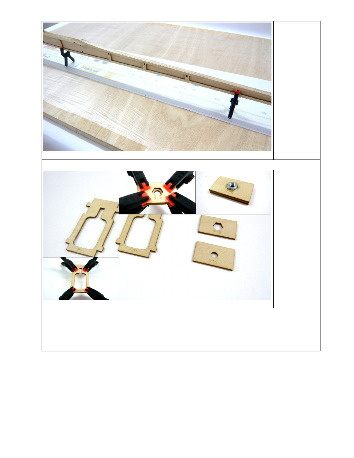
4
Sheet 72. 3
Parts R 8,
R 9, R2
Small parts
bag Part
R6
●Align and glue together (stack) both R2 parts using clamps (thick CA).
●Align and glue together (stack) R 8 and R 9 using clamps (thick CA).
●Glue the nut R6 using epoxy (5 minutes epoxy).
WARNING:Ensure no glue gets into the threads.
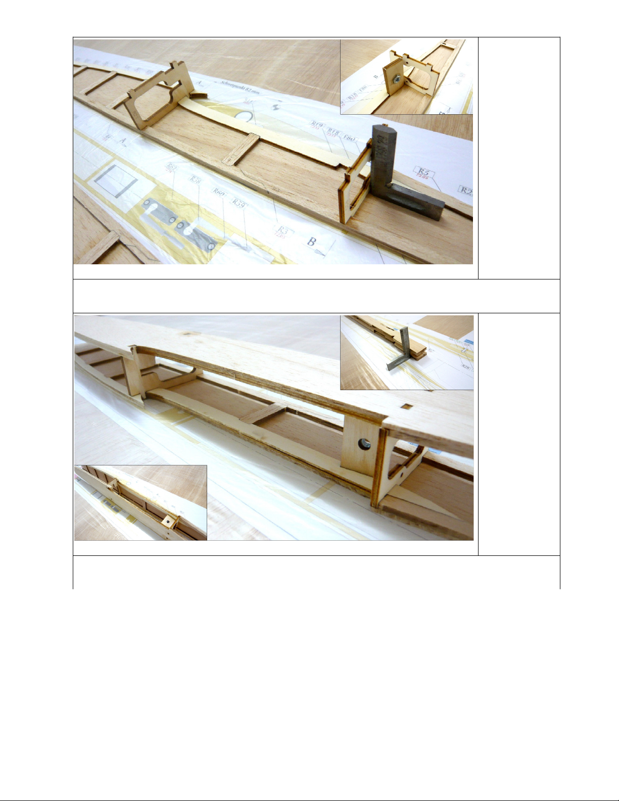
5
Sheet 72. 4
Parts R20
●Glue the wing saddle R 8/R 9 at right angle (5 minutes epoxy).
●Glue the R20 and R2 ribs exactly perpendicular (thin CA).
6
●Glue the second fuselage sidewall assembly. Use the same adhesives as in step 5.
●Check with a right angle that the fuselage sides are properly aligned with each other.

7
Sheet 72. 6
Part R22
●Glue the nose block R22 (thin CA).
●For this purpose make the fuselage with nose block perpendicular to a surface and
apply the adhesive on the inner surfaces of the side parts.
●The adhesive can penetrate the nose block, so perform this task installed over a plastic
film.
8
Sheet
72.05
Part
R28
OPTION
detachable
tailplane
Sheet 72. 4
Parts
R28. ,
R28.2
NOTE:The building step shown here describes the tail holder for a DETACHABLE elevator.
●If a nonremovable elevator will be installed, use balsa part R28 from sheet 72.05 to
save weight.
●Glue part R28. centrally to part R28.2(thick CA).
●Glue the nuts R63 in place (5 minutes epoxy).
WARNING:Ensure no glue gets into the
threads

9
Sheet 72.05
Parts R23-
R27
●Glue the pushrod sleeve guides R23 to R27 into the slots in R 2 to R 6 (thin CA). Use
the plan, protected by transparent film, as a guide to ensure that the fuselage is straight
and that the fuselage sides are vertical.
20
●Still over the plans, covered with plastic wrap, glue the tail holder from step 8. Make
sure the fuselage is straight and true (thick CA).
●File/sand a Vshaped slot opening (see marking in the small picture) to provide free
movement for the elevator connector. When making a nonremovable elevator, you
will sand through this part a bit. However, this is not critical.

2
Small parts
bag
Part R29
●With a thin round file (mouse tail file) or a 2 mm drill bit, rework the slots for the pushrod
guide tubes.
●Install the guide tube R29 and check the smooth running of the pushrod wire R56.
●Glue the guide tubes (5 minutes epoxy).
22
●Sand the fuselage ribs flush to the fuselage side parts.

23
Sheet 72.0
Parts R30-
R39
●Glue bottom fuselage sheeting (parts R30 to R39) (thick CA).
●Adjust the cutout for the rudder on part R39 to the fit the rudder.
24
Sheet 72.0
Parts R40-
R48
●Glue the top fuselage sheeting parts R40 to R48 (thick CA).
●NOTE:Be careful that the fuselage does not warp/twist.

25
Sheet 72.0
Parts R53a,
R53b
Sheet 72. 4
Part R54
●Glue the doubler of the battery flap R53.2 exactly centered on the part R53. (thick CA).
●Glue the siderails, R54 on both sides of R53 (thick CA).
The battery hatch cover should fit easily into the fuselage cutout.
26
Sheet 72.0
Parts R49-
R52
Long parts
bundle
Part R56
Small parts
Part R65
●Glue the front fuselage skin R52 (picture ) (thick CA).
●Glue the top sheeting R50 and R5 together at the abutting edges (pict. 2) (thick CA).
●Glue the holder R49 front flush and centered on the sheeting R50 (pict. 3) (thick CA).
●The hatch cover can be retained by a either wire or magnetic closure. For the wire
closing, use a short piece of guide tube R29. For the magnetic closure, glue a bar
magnet R65 in the cap holder (picture 3). The magnet in the battery compartment
should only be glued after covering with covering film — and verifying the polar
direction. (5 minutes epoxy)
●Slide the hatch cover in the fuselage. Leaving a 0.5 mm gap between the hatch cover
and R50, glue R50 and R5 to the fuselage (thick CA).

27
Sheet 72. 3
Part R55
●Screw the motor to the motor bulkhead R55.
●Wrap the motor in several layers of paper so that it fits snugly into the nosepiece. This
will ensure that the motor is centered and that the motor will turn freely after gluing the
bulkhead.
●Insert the motor and wires into the nose block with the motor bulkhead F55 attached.
●Using a small amount of glue, tack the motor bulkhead R55 to the motor nose block
and leave to dry (thin CA).
●Remove the motor, discard the paper, and glue R55 securely to R52 (thin CA).
28
●Sand the fuselage to round edges, etc., according to crosssection on the plan.

29
Sheet 73.03
Parts F4
Small parts
bag
Parts F5,
F68
●Glue one F4 to one of F6 rib each, making sure it is flush (thick CA). The locking pin
F68 can be used as a guide but do not glue F68 into place.
●Fasten the latch F5 with a little glue (thick CA). WARNING:It is important to leave
clearance
for clip F8 , so do not get glue into this space. NOTE:The kit contains four clips F8 , two
of which are spares.
●Glue the second rib F6 and clamp to a straight board until dry (thick CA).
30
Sheet 73. 2
Part F3
Sheet 73.09
Part F2
●Glue the center rib F2 on the plywood rib F3 (thick CA).
●Glue the second plywood rib F3 and clamp assembly to to a straight board to dry (thick
CA).

3
Sheet 73.03
Parts F7F9,
F
Sheet
73.
Part
F 0
Long parts
bundle
Part F
●Dryfit the rib combination F6/F4/F6 and all ribs labeled F7, F8, F9 and F onto the
spar tube F , according to the plan.
●Insert the servo frame F 0 between the ribs F8 and F9.
32
Sheet 73. 0
Part F 2
●Pin the trailing edge F 2 over the plan.
●Gently push the ribs down into the recesses of the trailing edge and align according to
plan. WARNING:The flat base of the ribs must rest their entire length on the building
board.
●Align the ribs vertically and glue to spar tube F and to trailing edge F 2 (thin CA). Use
thick CA to fill the gaps if void can still be seen between the spar tube and the ribs. The
ribs must be glued around the entire circumference of the spar (thick CA).
●Using a small round file, shape the spar cutouts in the two rib combinations F6/F4/F6
to match the angle template W , ensuring to shape one lefthanded and one right-
handed cutout.
●Slide the F6/F4/F6 rib combinations and glue to spar tube F using the angle template
W for proper alignment (thin CA).

33
Long parts
bundle Part
F 3
Sheet
72.03
Parts F 4
●Glue in the leading edge F 3 (thin CA).
●Glue in the half ribs F 4 (thin CA), aligning them carefully over the plan.
34
Sheet 72.09
Parts F 5,
F 6
NOTE:All reinforcements are glued flat down on the plan.
●Double up reinforcements F 5 (thick CA).
●Checkfit the two doubled F 5, trim as required, then glue in (thin CA).
●Glue in the two inboard reinforcements F 6 (thin CA).
●Checkfit and trim the outboard reinforcements F 6 to match the angle of the combination
ribs F6/F4/F6 and glue into place (thin CA).

35
●Plane the trailing edge to match the profile of the ribs (airfoil) and sand carefully.
●Cut away the excess (length) of the leading edge F 3 (the black rod)and the spar
(the carbon tube) with a fine metal saw carefully, and sand completely flush.
36
Sheet 73. 3
Parts F72-
F75
●Glue together the servo covers from parts F72, F73 and F74 (thin CA). WARNING:
Ensure to assemble three lefthanded and three righthanded servo covers according to
the plan.
●Glue the covering frame crossmember F75 flush with the servo frame F 0 (thick CA).
●Sand the complete wing center panel.
Table of contents