Grupo Azkoyen MODULAR XV Series Manual

10182 E 06 - 2005
Technical information: MODULAR VALIDATOR XV 1
MODULAR XV

10182 E 06 - 2005
Technical information: MODULAR VALIDATOR XV 2
1. INTRODUCTION AND DESCRIPTION OF COMPONENTS.............................................3
1.1 MODELS IN THE XV RANGE ..............................................................................3
1.2 PHYSICAL CHARACTERISTICS...........................................................................4
1.3 TECHNICAL CHARACTERISTICS......................................................................... 5
1.4 DESCRIPTION OF COMPONENTS ....................................................................... 8
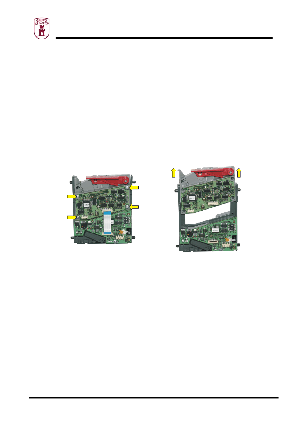
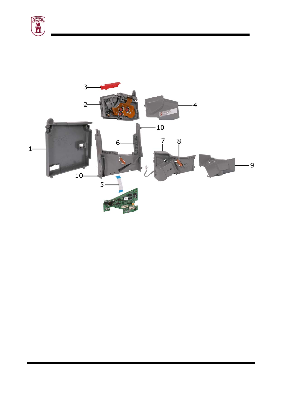
1. Cover ............................................................................................................8
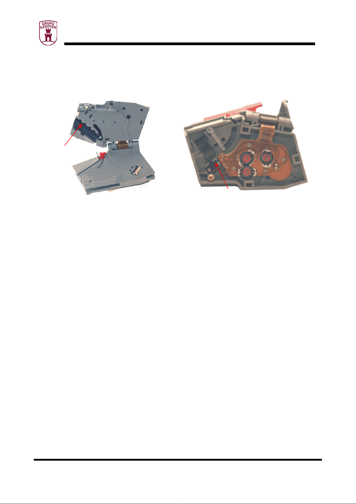
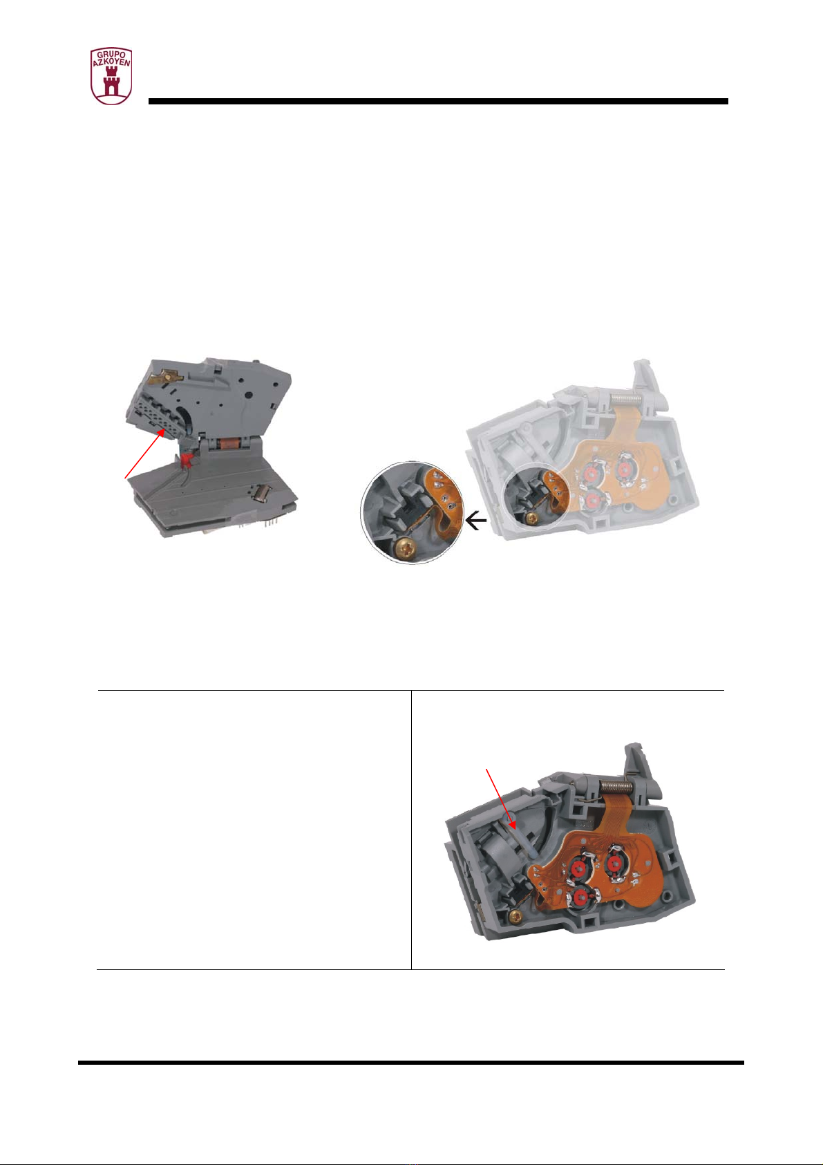
2. Sensor module ............................................................................................... 9
3. Recuperation lever ........................................................................................ 12
4. Sensor module cover ..................................................................................... 12
5. Communication bus for the entry and sensor modules ........................................ 12
6. Outlet module .............................................................................................. 12
7. Acceptance gate ........................................................................................... 13
8. Anti return ................................................................................................... 13
9. Acceptance gate cover ................................................................................... 13
10. Anchorage pivots ....................................................................................... 13
2. FUNCTIONING PRINCIPLES................................................................................ 14
2.1 Parallel mode ............................................................................................... 14
2.2 Timing mode ................................................................................................ 15
2.3 Credit mode ................................................................................................. 17
3. WORKING CONDITIONS AND NORMS.................................................................. 19
4. CLEANING AND MAINTENANCE .......................................................................... 20
5. DIMENSIONS................................................................................................... 21
6. PIN OUT.......................................................................................................... 22
7. ACCESSORIES ................................................................................................. 24
7.1 Funnels ....................................................................................................... 24
8. Large funnel .................................................................................................... 24
9. Medium funnel ................................................................................................. 24
10. Small funnel .................................................................................................... 24

10182 E 06 - 2005
Technical information: MODULAR VALIDATOR XV 3
1. INTRODUCTION AND DESCRIPTION OF COMPONENTS
This Technical Manual provides technical information corresponding to the coin validator in the
XV series which is part of the Modular range.
The coin validators are apparatus that, within the machine, and forming part of it, have the
task of selecting and validating coins introduced into the machine and can work in different
ways: parallel, credit and timer. The price of a credit or game, the time the game lasts and 2
tokens and their classification can be programmed.
In the rest of this Technical Manual the coin validators in the Modular XV range
will be called validator or validators
When the word configurable is used in the Technical Manual it means that the
parameter or characteristic it refers to can be programmed by the user to suit the
needs of the customer.
This programming is done using the PC application called HEUS (User Tool).
1.1 MODELS IN THE XV RANGE
The validators are divided into two groups depending on the sensor module:
•XV-6S
This is a validator with high sensorisation, whose sensor module has 6 optic sensors, 6
inductive sensors and one acoustic sensor. It is recommended when a high
discrimination of coins is necessary, principally for frauds.
•XV-2i
This is a validator with normal sensorisation, whose sensor module has 6 optic sensors
and 2 inductive sensors.

10182 E 06 - 2005
Technical information: MODULAR VALIDATOR XV 4
1.2 PHYSICAL CHARACTERISTICS
These validators are characterised by:
¾All the coin validators in the Modular range, and therefore in the XV series, are
compatible with the industry standards
¾The coin entry is in the top part.
¾The rejected/refunded coin goes to the bottom right.
Coin entry
Coin accepted Coin rejected
¾The accepted coin exit is located on the left as in the Lrange and the opposite of the A
range.
¾It has four studs on the side for its placement in the front plate.

10182 E 06 - 2005
Technical information: MODULAR VALIDATOR XV 5
1.3 TECHNICAL CHARACTERISTICS
The most relevant technical characteristics are:
ÔIndependent sensor module which is common for all models
Made using the most advanced technology, among other things, it has a flash memory
which allows the firmware to be programmed and teleprogramming from a PC or using
the TL20 or TL21 tool.
The sensor module is interchangeable with all the other models in the Modular range,
which is a great innovation in the logistics process.
To remove the sensor module it is necessary to remove the four screws indicated by the
arrows.
ÔOutput module
As with the sensor module, it is made with the latest technology and also has a flash
memory that allows the firmware to be programmed and teleprogramming from a PC or
using the TL20 or TL21 tool.
The great innovation incorporated in this module is the configuration file that can be
changed by the user to modify all the configurable parameters and in this way adapt the
validator to the user’s necessities.
The changing of the configurable parameters is done with a PC or with an application
called HEUS (user tool).

10182 E 06 - 2005
Technical information: MODULAR VALIDATOR XV 6
The outlet module is unique for the different series or references that make up the
Modular range.
ÔPower supply and electrical consumptions for the standard model
The nominal voltage is 12 Vdc or 24 Vdc admitting a minimum of 10 Vdc and a
maximum of 27 Vdc.
Electrical consumption:
Powered at 12 Vcc.
Validating a coin 50 mA
Maximum (activating the
acceptance gate)
400 mA
Average per coin 235 mA
ÔAdmission of coins
The validator admits 32 types of different coins, of which 2 can be reprogrammed by
the operator on site by putting the validator in “learning” mode.

10182 E 06 - 2005
Technical information: MODULAR VALIDATOR XV 7
ÔString detection system
All the models include an efficient string detection system which detects any attempt at
fraud using a string attached to a coin to obtain free credits.
String detection system
ÔMean time between failures (MTBF)
Under normal working conditions, these validators have a MTBF of 1.3 validators of
every 100 per year.
ÔMean cycles between failures (MCBF)
Under normal working conditions, these validators have a MCBF of 840,000 coins.
ÔConstruction material
The latest generation plastics resist wear and dissipate static electricity, are made of
high rigidity and are dimensionally stable at high temperatures and humidity (low
absorption levels) and resist saline deposits.
ÔRefund code
It has a system that generates a “refund code” when the validator door is opened. This
code can be activated or deactivated by the user and is generally used to indicate to the
machine that a refund is being requested.

10182 E 06 - 2005
Technical information: MODULAR VALIDATOR XV 8
1.4 DESCRIPTION OF COMPONENTS
1. Cover
This cover protects the electronic elements in the validator.

10182 E 06 - 2005
Technical information: MODULAR VALIDATOR XV 9
2. Sensor module
This element has the majority of the parts responsible for measuring and control in the
validator. It is a common element of the validators that have the same sensor configuration.
The principle elements that the sensor module has are:
JP100: Communication bus for the
outlet module
JP101: Serial port
JP102: Programming connector

10182 E 06 - 2005
Technical information: MODULAR VALIDATOR XV 10
Inside the sensor module is the “string detector system”. An electro-mechanical system to foil
any attempt at fraud using a string tied to the coin. The system is based on an infrared beam
passing through a hole in the shutter. The beam is interrupted when the string attached to the
coin tenses and moves the shutter. The validator interprets this signal as a fraud attempt and
inhibits the coin.
The coin entry rocker is designed to
stabilize the speed at which the coins move
through the interior of the validator.

10182 E 06 - 2005
Technical information: MODULAR VALIDATOR XV 11
In the lower part of the entry model is the
acoustic sensor. This device receives the
sound made by the coin when it hits the
metallic cylinder on falling into the
validator. The parameters received by this
sensor are very important in the coin
acceptance or rejection process.
Depending on the model, the validator has
between 2 and 6 inductive sensors that
obtain coin parameters related to its
thickness and alloy. Its design favours the
reading of coins manufactured using
bimetallic technologies and/or multilayer.
An example of these technologies is the
€1 and €2 coins.
3 pairs of infrared sensors that obtain
parameters related to the diameter of the
coin.

10182 E 06 - 2005
Technical information: MODULAR VALIDATOR XV 12
3. Recuperation lever
Activating this lever will open the validator to free possible coin jams within the validator and if
the refund code is activated it will be generated.
4. Sensor module cover
This cover protects the PCB.
5. Communication bus for the entry and sensor modules
This communicates the entry and sensor modules. Disconnect from the sensor module by
pulling on the connector cover on either end of the cable, the cable will come out
effortlessly.
6. Outlet module
This element manages the communication between the validator and the machine it is installed
in. All the configurable parameters that can be configured by the user are found here. Its PCB
has a “flash memory” that can be reprogrammed with a PC or the TL20 tool and procedures
that are described in the Technical Manual of the “User Tool” (HeUs).
It also houses the optic sensors, a photodiode and a phototransistor, that detect the presence
of an accepted coin.
The infra-red beam that the photodiode emits passes through a prism (see fig. acceptance
gate) to the phototransistor, this beam is only interrupted by the passing coin that has been
accepted.

10182 E 06 - 2005
Technical information: MODULAR VALIDATOR XV 13
Outlet module PCB
J1: 10-way bus. It communicates
with the machine.
J2: Communication bus with the
sensor module.
J3: Programming the microprocessor
J4: Acceptance gate
J5: Links
A: Photodiode
B: Phototransistor
C: Dipswitches
7. Acceptance gate
When the validator validates a coin, the electromagnet opens the gate to let the coin through
the accepted coin channel.
The solenoid is powered by 12 Vdc.
8. Anti return
This mechanical element impedes the return of the coins using a string.
9. Acceptance gate cover
It protects the acceptance gate assembly; it is held by anchoring “clips”.
10. Anchorage pivots
These anchorage elements on the validator hold it inside the machine and have a ø of 4.5 mm
and are 5 mm long.
Prism
Anti return
Gate

10182 E 06 - 2005
Technical information: MODULAR VALIDATOR XV 14
2. FUNCTIONING PRINCIPLES
It has three working modes: Parallel, Timer and Credit.
To configure the different working modes use the four dipswitches (SW), as shown in the
table:
Working modes
Parallel
Timer
Credit
SW1 OFF ON OFF
SW2 OFF OFF ON
SW3 OFF OFF OFF
SW4 OFF OFF OFF
2.1 Parallel mode
The validator working in Parallel mode gives a signal to identify the coin through one
or more lines when a coin is accepted.
¾These validators have 7 lines that can be:
- dedicated: which means that only 6 different coins can be validated as one line is
used to identify each coin.
- binary: which means various lines can be used to identify a coin, with a maximum
of 32 different coins.
As all the lines in these validators are configurable, the 7 lines can be used to
identify coins or other tasks.
¾The duration of the pulses is configurable data.
¾The exit assignation is configurable data.
ON
OFF

10182 E 06 - 2005
Technical information: MODULAR VALIDATOR XV 15
¾Working in this mode, when a coin is validated one pulse of a determined duration is
given through an assigned line. An Azkoyen sorter can be controlled using pins 3, 4 and
5. This implies the use of a different exit module PCB.
In any of the working modes described below, take into account the
following information:
When the amount introduced goes over the price of the service the validator does
not accept coins and will not accept any more until the services that are
accumulated in the validator are used up.
2.2 Timing mode
The validator working in Timing mode gives time when the programmed price is
reached. This time is configured by the user.
This validator offers three working modes:
¾Work for a continued time.
On accepting the coin, the time signal is automatically given all at once, without
varying the state of the pin until it is finished. The pin is configurable.
Pin 6 works as inhibition in accepting the coin. The inhibition is configurable to level
“0” or “1”.
¾Work for a continued time with Service Request.
On accepting the coin, the time signal is given all at once when the user requests it
through pin 6. For this to happen it is necessary for pin 6 to change state, that is
form active (0 or 1, depending on the configuration) to inactive for a minimum of 50
milliseconds. It is necessary fir the pin to return to inactive state for a minimum of
50 milliseconds to be able to sell the following signal.

10182 E 06 - 2005
Technical information: MODULAR VALIDATOR XV 16
Example:
Active Inactive
Pin nº6: Service request 0 1
Service output pin 0 1
1
Æ50 msec Å
Input pin nº 6 0
1
0 ÆTotal service timeÅService output
pin
¾Work for Service Request.
Through pin 6 the time signals are requested one by one. For this to happen it is
necessary for pin 6 to change state, that is form active (0 or 1, depending on the
configuration) to inactive for a minimum of 50 milliseconds.
It is necessary for the pin to return to inactive state for a minimum of 50
milliseconds to be able to sell the following signal.
Example:
Active Inactive
Pin nº6: Service request 0 1
Service output pin 0 1
1
Æ50
msec
ÅÆ50
msec
Å
Input pin nº 6
0
Æminimum 50
msecÅ
1
Service output pin 0
ÆTime of first
serviceÅ
ÆTime of second
service Å

10182 E 06 - 2005
Technical information: MODULAR VALIDATOR XV 17
In the three working modes, a counter pulse can be programmed, which will appear each
time the value of the coin counter that is programmed is reached, the duration can also be
programmed, as much in the time ON as in the time OFF. An electro-mechanical counter is
usually used.
For example, if the base coin is €1, when two 50-cent coins (1€) are introduced, a counter
pulse is produced, or when five 20-cent coins (1€) are introduced, it also produces a
counter pulse. The pulse on this line is configurable.
In the three working modes a credit available signal is produced. It is usually used for a
credit lamp to inform the user that there is a credit. The signal on this line is configurable.
In the three working modes a warning signal can be activated to advise of an imminent
end to the service when a certain time is left, time also configurable. The signal on this line
is configurable.
The counter, credit available and warning signals are all configurable: they
may, or may not, be in the final configuration of the validator
2.3 Credit mode
The validator working in Credits mode gives a credit signal when the price
programmed is reached. This signal has a configurable length for “1” and “0”. The
pin is also configurable.
These validators offer two working modes:
¾Working with continuous pulses
It accepts the coin and automatically, gives the credit impulses consecutively until
they are finished. The output pin is configurable.
Pin 6 works as inhibition in accepting the coin. The inhibition is configurable.

10182 E 06 - 2005
Technical information: MODULAR VALIDATOR XV 18
Example:
Active Inactive
Credit output pin 0 1
1
0 1st 2nd 3rdCredit output pin
¾Working with Service Request
Through pin 6, the pulses are requested one by one. For this to happen pin 6 must
go from inactive to active for a minimum of 50 milliseconds. Then it must go back to
inactive for a minimum of 50 milliseconds to be able to sell the following signal.
Example:
Active Inactive
Pin nº6: Service request 0 1
Credit output pin 0 1
1
Æ50
msec
ÅÆ50
msec
Å
Pin nº 6
0
Æminimum 50
msecÅ
1
Credit output pin 0 1º 2º
In both working modes, a counter pulse is produced, which will appear each time the value
programmed is reached, the duration of the pulse is also configurable in the duration of the
time ON and the time OFF. It is used to count with an electro-mechanical counter.

10182 E 06 - 2005
Technical information: MODULAR VALIDATOR XV 19
For example, if the base coin is €1, when two 50-cent coins (1€) are introduced, a counter
pulse is produced, or when five 20-cent coins (1€) are introduced, it also produces a
counter pulse. The pulse on this line is configurable.
In both working modes, a credit available signal is produced. It is usually used for a credit
lamp to inform the user that there is a credit. The line for this signal is configurable.
The counter and credit available pulses are both configurable: they may, or
may not, be in the final configuration of the validator
A warning pulse does not exist in either of the working modes
3. WORKING CONDITIONS AND NORMS
Optimum results from using this equipment can be obtained by meeting the following
requirements:
- Install the Coin validator with a maximum inclination of +/- 3º on all axes.
- Temperatures:
ÔStorage: from -25 to +70ºC.
ÔWorking: Optimum 25ºC. The recommended margins are from +5 to +55ºC with
double the reject rate at the extremes.
- Humidity: maximum 95% (relative humidity without condensation).
- Norms that are met.
ÔEN50081-1. General emission norm
zEN50022: Radiated emission (measurement of the radiated perturbation field).
zEN50022: Conductive emission (measurement of the conductive perturbations
in power supply).
ÔEN50082-1: General immunity norm.
zIEC801-2: Electrostatic discharges (measurement of the immunity to
electrostatic discharges).

10182 E 06 - 2005
Technical information: MODULAR VALIDATOR XV 20
zIEC801-3: Radiation immunity (measurement of the immunity to electric
fields).
zIEC801-4: Transitory peaks and spikes (Measurement of the immunity of
transitory peaks and spikes).
ÔEN60335-1 (94-95). Electrical appliance safety norm
ÔCE
4. CLEANING AND MAINTENANCE
The amount of dirt coins leave and the foreign objects and dirt that may obstruct its elements
determine the maintenance the coin validator requires. Use the following guidelines for
cleaning:
- Disconnect the power.
- Clean the dirty areas with paint brush or brush with fine vegetable fibres (never metal)
impregnated with alcohol. Clean well the coin routes and the optic sensor openings.
WARNING:
Never remove the parts that are held with screws, manipulating the may provoke them to
work incorrectly.
Never use products that contain benzene hydrocarbons. These products severely degenerate
the plastic parts producing irreparable damage.
Never submerge the Coin validator in any liquid.
This manual suits for next models
2
Table of contents
Popular Accessories manuals by other brands

Somogyi Elektronic
Somogyi Elektronic Home HSB120 instruction manual

Extron electronics
Extron electronics OCS 100W Setup guide

IFM Electronic
IFM Electronic efector100 GG507S installation instructions

Hytera
Hytera CHU-P1BA01 manual

WallSenzr
WallSenzr BDS-700 Series installation instructions

FlexLink
FlexLink XS Maintenance manual

SEELEY INTERNATIONAL
SEELEY INTERNATIONAL Climate Wizard CW-6S installation manual

Vega
Vega VEGAFLEX 62 operating instructions

turck
turck FCS-G1/2TN-NAEX manual

2E mechatronic
2E mechatronic 6220312 instruction manual

Amana
Amana IC7 Installation and operating instructions

Klarstein
Klarstein Beer Baron manual