Gsertel RCS 100 User manual

RCS 100 - RCS 400
Remote monitoring systems
Version 11.04
User Manual

RCS User Manual
2
Index
Safety Requirements........................................................................................................................................ 5
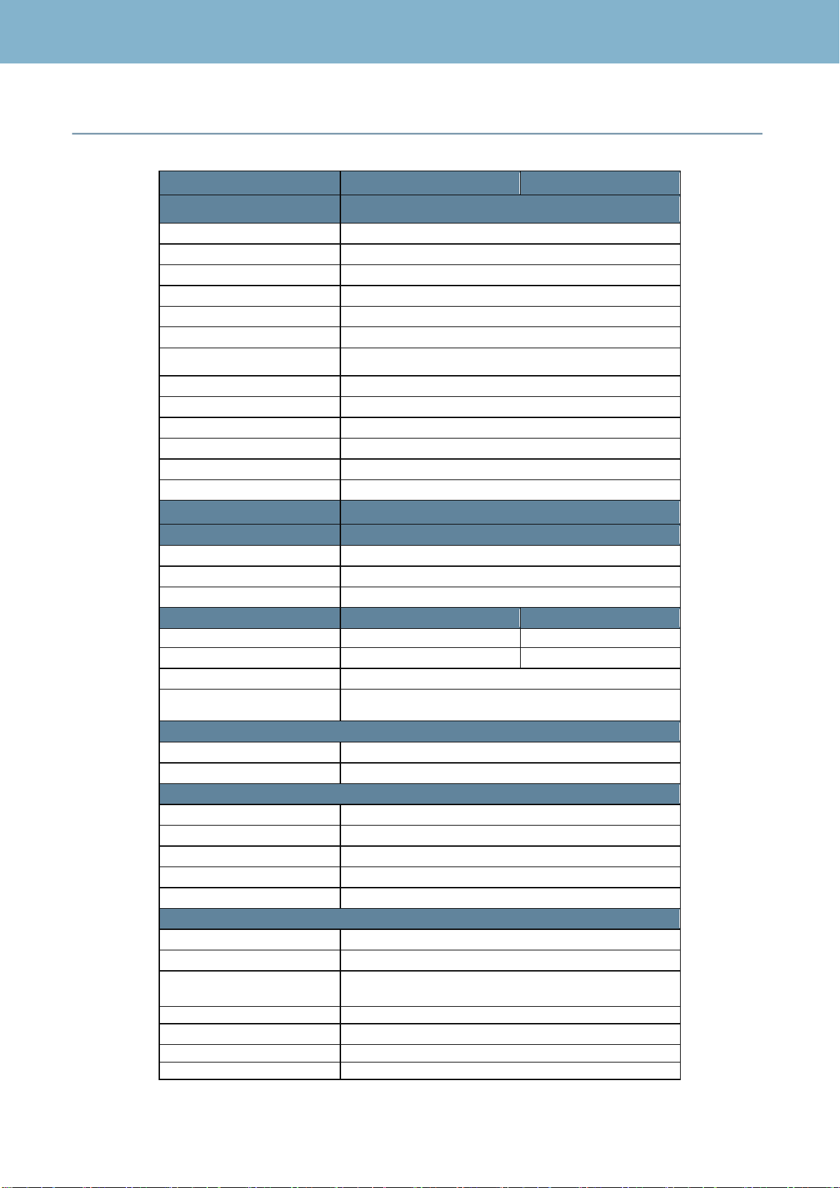
Specifications.................................................................................................................................................... 7
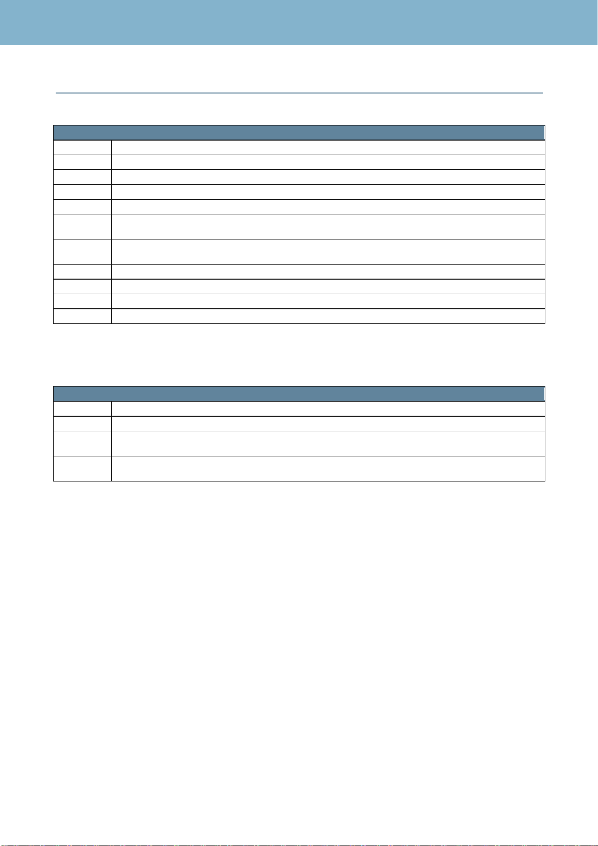
Table of options............................................................................................................................................... 10
Overview.......................................................................................................................................................... 11
Description of Equipment Components:...................................................................................................... 11
Start Up............................................................................................................................................................ 13
RCS Web Application..................................................................................................................................... 15
1.- RCS Setup............................................................................................................................................. 16
1.1.- System Configuration.................................................................................................................... 16
1.1.1.- System......................................................................................................................................... 16
1.1.2- System Users............................................................................................................................... 23
1.1.3.- System Info.................................................................................................................................. 24
1.2.- Input/Output.................................................................................................................................... 30
1.3.- Channel Plans................................................................................................................................ 32
1.3.1.- RF Channel Plans...................................................................................................................... 32
1.3.2.- ASI................................................................................................................................................ 34
1.3.3.- IP Channel Plans (only for IP inputs -option 902518-)......................................................... 34
1.4.- Utilities............................................................................................................................................. 38
1.4.1.- DataBase Management............................................................................................................. 38
1.4.2.- Import/Export............................................................................................................................... 38
1.4.3.- Cloning......................................................................................................................................... 39
1.5.- Profiles............................................................................................................................................. 40
1.5.1.- Alarms Profiles............................................................................................................................ 40
1.5.2.- Bitrate Measure Profile.............................................................................................................. 45
1.5.3.- Profiles shortcut.......................................................................................................................... 46
2. Dashboard............................................................................................................................................... 47
3. All in One................................................................................................................................................. 49
4.- TS Analysis............................................................................................................................................ 57
4.1.- Bit Rate............................................................................................................................................ 57
4.2.- Table Repetition............................................................................................................................. 58
4.3.- EPG ................................................................................................................................................. 58

RCS User Manual
3
4.4.- PCR Jitter -Option 902512 only for RCS100 and RCS400-.................................................... 60
4.5.- Tree View........................................................................................................................................ 61
4.6.- Service Monitoring-Option 902558-............................................................................................ 62
4.7.- RDS Analysis.................................................................................................................................. 63
4.8.- TS Recorder................................................................................................................................... 64
4.9.- Quality of Service........................................................................................................................... 65
4.9.1- SLA................................................................................................................................................ 66
5.- RF Analysis............................................................................................................................................ 68
5.1.- Measurements................................................................................................................................ 68
5.2.- Constellation -Option 902511-..................................................................................................... 69
6.- Spectrum -Option 902511-.................................................................................................................. 70
7.- Polling..................................................................................................................................................... 73
7.1.- Polling.............................................................................................................................................. 73
7.2.- Historical Pollings .......................................................................................................................... 75
7.3.- Configuration.................................................................................................................................. 76
8.- Alarms..................................................................................................................................................... 79
8.1.- View................................................................................................................................................. 79
9.- Historical................................................................................................................................................. 80
Local Features................................................................................................................................................. 83
Maintenance.................................................................................................................................................... 85
Technical Support........................................................................................................................................... 87
Warranty........................................................................................................................................................... 88

RCS User Manual
4

RCS User Manual
5
Safety Requirements
Product Inspection
Inspect the equipment for shipping damage. Should any damage be discover, immediately
file a claim with the carrier.
Read and follow all instructions
All the safety and operating instructions should be read prior to and follow while operating
this product.
Symbols and safety labels
Symbol
Meaning
Warning: General danger point
Shock hazard
Grounding
Cleaning
Follow the cleaning instructions contained in the Maintenance sections of this manual.
Attachments
Do not use attachments that are not approved by the product manufacturer.
Water and Molsture
This product is not water resistant. Do not use in conditions where condensation may exist.
The entry of water increases the risk of electric shock.
Grounding or Polarization
Do not bypass or defeat electrical plug polarization or grounding. Doing so will violate the
warranty and may pose a risk of fire or electrocution.
Wire Protection
Ensure all connected wiring is routed correctly to avoid damage including pinching,
excessive bends, or compression. Never use the product if damaged cable network
connection.
Electrical Supply, Grounding, and Surge Protection
Ensure that all local or national electrical codes are followed. The products of safety class I
with movable power and single plug can only be plugged into sockets with safety pin and
protective conductor connected.

RCS User Manual
6
The interruption of the protective conductor is prohibited in both the plug and the meter. The
disruption may result in the risk that the product is a source of electric shock.
Do not overload wall outlets, extension cords or power strips as this may cause fire or
electric shock.
Power Lines
Always use caution and avoid operating this or any connected equipment near uninsulated
power lines or any other hazards.
Servicing
There are no user serviceable parts in this equipment. Do not attempt to service this product
or remove covers. Refer all servicing to qualified service personnel. Follow the instructions in
this manual when replacing the fuses.
Heat
The product should be situated away from heat sources such as radiators, heat registers,
stoves, or other products (including amplifiers) that produce heat.
Ventilation
Make sure the fans are not obstructed when placing the equipment in the rack, so that the
air can circulate.

RCS User Manual
7
Specifications
RCS 100
RCS 400
General Specifications
Display
Graphic LCD STN. Resolution:256x64
Format
1U 19” rackable unit
Weight
3250 g.
Dimensions
448x380x43.3mm
Operating temperature
-5ºC to 45ºC (23ºF to 104ºF)
Storage temperature
-20ºC a 70ºC (-4ºF a 158ºF)
Humidity
5% to 95% non-condensing
Interfaces
Web and keyboard
Power supply
100-240 VAC 50-60Mz 1.4A
Storage capacity
500 GB
Internal GPS
Option 902566
LNB Powering
√
DiSEqC
Up to 4 different satellites on each input
Technical Specifications
Frecuency
Range
250-2400MHz
Resolution
100 KHz
Tuning
Channel and frequency
Inputs
RCS 100
RCS 400
RF
1 x F 75Ω connector
4 x F 75Ω connector
ASI
1 x BNC 75Ω connector
4 x BNC 75Ω connector
IP
Option 902518
Dashboard with the status of all
the inputs
√
Outputs
ASI
1 x BNC 75Ω connector
A/V
1 x HDMI 1.4
Spectrum Analyzer (Option 902511 only for RCS100 y RCS400))
Span
10, 20, 50, 100, 200, 500, 1000 MHz
Scale
-100 dBm to 20 dBm
Max. and Min. Hold
√
Marks
2
Mask
√
RF Analysis
Demodulation
ETSI EN 300421 (DVB-S), ETSI EN 302307 (DVB-S2)
Constellation
QPSK, 8PSK, 8APSK, 16 APSK Y 32 APSK
U.A.L. Technology (Universal
Auto Lock)
Automatic detection of signal characteristics and
modulation parameters
Power
20 –120 dBuV
C/N
Up to 20 dB
MER
Up to 20 dB
DVB-S Measures
CBER: 9.9E-2 –1.0E-6

RCS User Manual
8
VBER: 9.9E-2 –1.0E-8
DVB-S2/S2X Measures
(supports ISI -Input Stream Identifier-
and PLS -Physical Layer Scrambling-)
LDPCBER: 9.9E-2 –1.0E-6
BCHBER: 9.9E-2 –1.0E-8
LM: Up to 10 dB
Accuracy
+- 2dB
Resolution
0.1 dB
Constellation Diagram
Option 902511
Polling Feature
√
TS Analysis
Service Bitrate
√
Table Bitrate
√
PID Bitrate
√
Captures of all Services
√
Tree View
√
Scramble Status
√
Table Repetition
√
PCR Jitter Graphs
Option 902512
ETSI TR 101 290
Level 1, 2 and 3 priority errors (Level 3 option 902512)
Live Streaming of the selected
service
Option 902520
Manual TS Recording
Option 902519
Alarm TS Recording
Option 902519
RDS Analysis
√
Electronic Program Guide
√
Loudness metering according
EBU Tech Doc 3341
Option 902569
Black and Freeze Detection
Option 902568
Audio Silence Detection
Option 902568
QoS measurements
Option 902538
IP Measurements (Option 902518 only for RCS100 and RCS400)
Maximum arrival interval
between packets
√
Minimum arrival interval
between packets
√
IP payload bitrate
√
UDP payload bitrate
√
Media loss rate
√
Loss IP frame
√
Corrected IP
√
Polling
√
Alarms
4 groups: RF, Levell1, Level2,
Level3
√
(Level 3 option. 902512)
Configurable type of alarm
(Info, Warning, Error)
√
TS recording by alarms
Option 902519
System alarms
Temperature, Power supply (only for RCS with double
power supply) and alarms deletion
Quality of Service alarms
Option 902538

RCS User Manual
9

RCS User Manual
10
Table of options
Options RCS 100 and RCS400
902511
Advanced RF Measurements (Full Spectrum Analysis, Constellation)
902512
Advanced TS Measurements: Third priority alarms, PCR Jitter
902518
IP INPUT - Includes 2 flow processors
902519
Transport Stream Recording
902520
Live Streaming
902521
Additional IP flow processor (Máx. 4 IP flows processors).
Total processing capacity available (RF+ASI+IP) : 300 Mbps
902527
Redundant IP INPUT (backup input) Additional IP flow processors are required for simultaneous
TS analysis with main IP Input
902558
PID monitoring and Bitrate monitoring
902564
DVB-CI Slot
902568
Black and Freeze and Audio Silence Detection
902569
Loudness metering according EBU Tech Doc 3341
Technical support options
902525
12 months RCS 100 support (12 months of e-mail technical support and software updates)
902524
12 months RCS 400 support (12 months of e-mail technical support and software updates)
902523
12 months RCS 100 support and warranty (12 months of extended warranty, e-mail technical
support and software updates)
902522
12 months RCS 400 support and warranty (12 months of extended warranty, e-mail technical
support and software updates)

RCS User Manual
11
Overview
The RCS is a powerful tool to monitor and analyze the Transport Stream traffic that carries
information of audio, video and data of the DVB-S, DVB-S2, and DVB-S2X digital television
channels.
The RCS 100 is able to analyze one RF and one ASI inputs. The RCS 400 is able to analyze up to
four RF inputs and four ASI inputs.
Description of Equipment Components:
Front:
LCD Display
Menu selection buttons
Navigation buttons within each menu
OK Button. Selects the parameter in the submenu
Back Button. Closes the submenu if open
Home Button. Return the control of the equipment when it is being controlled remotely
Setup Button. Provides Access to the setup options of the menu
LEDs. Power: Indicates whether the equipment is turned on.
Remote: Indicates whether there is someone connected to the equipment through the
web application.
Error: The error LED lights up when the equipment detects an operating error.
CI card Slot
1
2
2
5
6
4
3
3
2
3
4
5
6
7
1
8
8
7
9
9

RCS User Manual
12
15
14
Back:
RF input
ASI IN
ASI OUT
TSoIP
Control
HDMI
USB
Power Supply
8
8
9
10
11
14
12
15
9
10
11
8
9
10
11
13
12
15
RCS 100
RCS 400
14
13
12
13

RCS User Manual
13
Start Up
1.- Place the RCS in the rack
2.- Connect the RCS to power supply
3.- Connect the RCS to internet, using the Ethernet connector
4.- Turn the RCS on pressing the button
5.- When the RCS starts, the display will show the Info menu, so you will see the IP assigned to
your RCS . By default, the RCS is shipped in DHCP mode, so the IP will be assigned automatically.
To enter a certain fixed IP, press the Setup button and select the STATIC option. Then you must
enter an IP address within the range of your network, using the buttons , and
6.- Open a web browser (Google Chrome recommended) on your computer, tablet or smartphone.
7.- Copy the IP address showed in the Info screen of your RCS into the address bar of your web
browser:
8.- Then it will be open the remote control application of your RCS.
17
14
19
7
2
3
4

RCS User Manual
14
To access the application, you must introduce an user name and the corresponding password. For
the first time, you must use the following ones:
User: admin
Password: rcs
Once you have entered in your application, you will be able to change your user name and your
password.

RCS User Manual
15
RCS Web Application
The RCS web application is organized in various sheets. Each sheet groups several features. In this
way, the user has an easy and quick access to any function.
The first time the user open the application, it will appear the “Dashboard” sheet selected:
All the features of the application will be explained bellow.
Select the input by clicking the corresponding
button (*)
Access the settings by clicking the gear
Wheel. To get out, click on the door icon
(*)RCS100: RF1, ASI1 or IP (IP option 902518); RCS400: RF1, RF2, RF3, RF4, ASI1, ASI2, ASI3, ASI4 or IP (IP option
902518)
Click to see all the users connected to the RCS

RCS User Manual
16
1.- RCS Setup
In the top right of the screen, there is a gearwheel icon. When you click on it, you will access the
configuration menu.
Only system administrators and technicians have access to the RCS configuration (see section 1.3.-
System users).
The configuration menu is organized in several sheets, that will be explained bellow:
1.1.- System Configuration
This feature allows set all the parameters of your equipment.
1.1.1.- System
In this tab you configure the network parameters, the date and the hour, the measure units, SNMP,
etc.
Device Alias: Allows to assign a name to the RCS.
Network: It is possible to set the network parameters manually or using DHCP. If you select manual
mode, you must introduce all the network parameters: IP address, DNS, etc. To save the changes
you must click the “Apply Settings” button. To verify that your RCS is connected to the internet, click
the button “Check Internet”.
Video IP Configuration (Option 902518): As is the case with network configuration parameters,
the parameters of the IP video input must be configured manually. So, you must introduce all the
network parameters: IP address, DNS, etc. This configuration applies to all the inputs and outputs
assigned to that port. You can also see the negotiation status, and you can select to force or select
the auto mode. To save the changes you must click the “Apply Settings” button.

RCS User Manual
17
SNMP: The RCS system incorporates a SNMP server to send packets of the generated alarms to a
server selected by the user. So that the user can receive alarms, he must have an SNMP client
whose IP address must indicate on the "Trap IP Address" field. It is also necessary to indicate the
“Trap Community”and “RW Community”. The user can also select the type of trap that you want to
send:
-Trap: the system sends the trap and doesn’t wait for confirmation.
-Inform: the system sends the trap, but it waits for the receiver to confirm that it has received
the report. In this case, the user must select the number of retries and the time interval
between them.
The mib file can be downloaded clicking on the “Download mib” button. In this way, the user can
check the data structure and the features with explanatory comments, to obtain the data from the
RCS trough SNMP.
IGMP: The IGMP protocol can be set agreement with the network configuration, allowing to select
the protocol version (Auto, V1, V2 or V3). To apply the configuration, click on the “Apply settings”
button.
Black and Freeze Settings: Allows to set the parameters needed to detect the black and freeze
events (only for RCS100 and RCS400 with the option 902568). These parameters are:
Window size: It defines the duration of the window analysis (in seconds) to detect black/frozen
images. By increasing this value, more robust the algorithm will be. The minimum recommended
value is 5 seconds.
Uniform variation analysis and Small packet analysis: These two parameters define the algorithm's
behaviour. You can switch on/off any of them to adjust the algorithm's performance to the video
source type. For instance, "Uniform variation analysis" is recommended for video sources generated
by FFMPEG tools.
Time interval rejection: Allows to disable all the Black and Freeze alarms in a period of time
(selected in start time and end time) each day. Note that all the alarms of all the services of all the
inputs will be disabled.
See section 1.5.1.- Alarms Profiles. The Black and Freeze alarms are configured in the Services
alarms profiles.
Ignored Services for B&F and Silence: Allows to disable the Black and Freeze and Silence
alarms more precisely, by selecting the services you want to disable the alarms for, as well as the
period of time for each one. In order to do that, you must introduce the SID of each service. See
section 3.1.- Bitrate to learn how to disable these alarms directly in the services list.
QoS Settings: Allows to set all the parameters needed to give an objective measure of the quality
of the service. The user has to configure three parameters for each group of measures (SAE+SAE
ratio / SDE+SDE ratio / SIE+SIE ratio). Those parameters are:
Time: It is the difference of time that the RCS uses to compare the errors indicated in the flags
parameter.
Window: It is the period of time over which the corresponding QoS measure is displayed.

RCS User Manual
18
Flags: The user has to select the errors to consider to obtain the corresponding QoS measurement.
Following you can see the method to obtain the SAE measurement (the SDE and the SIE
measurements are calculated in the same way:
Count the occurrence of error messages for the following parameters over a Time interval:
TS_sync_loss, PAT_error, and PMT_error (if all the Flags are selected).
For each Time interval, the following differences are calculated:
TS_sync_loss(Time) = TS_sync_loss(T) - TS_sync_loss(T-Time)
PAT_error(Time) = PAT_error(T) - PAT_error(T-Time)
PMT_error(Time) = PMT_error(T) - PMT_error(T-Time)
The Service Avaiability Error is the maximum of TS_sync_loss(Time), PAT_error(Time), and
PMT_error(Time). And the results over a Window period of time are displayed.
The Service Avaiability Error Ratio is the percentage of time for wich the parameter exceeds the
user-defined threshold.
SLA Settings: Allows to set the minutes that the RCS must take as a reference for the samples of
the SLA measurements. See section 9.- Quality of Service.
Audio Silence Settings: Allows to set the parameter needed to detect the audio silences events
(only for RCS100 and RCS400 with the option 902568). This parameter is:
Window size: It defines the duration of the window analysis (in seconds) to detect audio silence. If
the RCS detects that there is no sound during a time interval equal to Window size, the
corresponding alarm will be activated.
See section 1.5.1.- Alarms Profiles. The Audio Silence alarms are configured in the Services alarms
profiles.
TS Recording: The files of the TS recordings can be saved in the internal memory of the RCS, or in
a pen drive connected to the RCS. This option is available only when the RCS detects a pen drive.
In addition, the user must indicate the time he wants to record before (between 1 and 15 seconds)
and after (between 15 and 45 seconds) the event.
LNB: You can select the type of LNB that you are using in your installation: Universal, Wideband or
Custom. If you select Custom LNB, you must select the low and high band frequencies.
Date and Time: When you first open the web application, you must set the date, the hour, the
region and the zone of the system, so the data will be saved correctly.
Units: You can choose the units to use in your measurements, dBuV or dBm.
Numeric Format: You can choose the PIDs view mode (hexadecimal/decimal) as well.
Warning: The setup parameters must be handled by an expert. An arbitrary
change may cause problems in the system.

RCS User Manual
19
Temperature Information: Allows to show/hide the RCS temperature.
SCTE-65 configuration: Allows to setup the VCT_ID parameter (Virtual Channel Table ID) of the
SCTE-65 regulation (mainly used in USA).
Alarms Defaults: Returns all the alarms settings to the default factory values.
System Log: The RCS generates several types of reports that the user can download by clicking
on the “Download” button placed at the right. The different types of logs are explained below:
-System Log: contains a number of values of your equipment that may be very useful to our
developers if there is a failure in your equipment.
-Activity Log: contains the most relevant changes made to the meter by the users (such as
tuned channel changes, monitoring mode changes, etc.). It is also possible to download this
log by clicking on the icon placed in the top bar.
-Alarms Report Log: contains the emailing data of the alarms emails. See paragraph Alarms
Report in this section.
-Autoupdate Log: contains the information about downloads, updates, and licenses. The file
indicates if there was an error, or if, on the contrary, the process has been carried out
successfully. See paragraph Updates Server Configuration in this section.
Alarms Report: The RCS automatically generates and sends by e-mail an alarm report. It is
also necessary to select the frequency of the report: None/Weekly/Monthly, as well as the e-mail
address where the user wants to receive the reports. See section 1.2.- Input/Output.
It is also possible to generate and send a report of alarms that the user considers critical each
time one (or more) of these critical alarms occurs. The user can select up to 5 critical alarms,
indicating their ID in the Critical Alarms ID field. The Critical Alarms Report Period field indicates
the time that must elapse, at least, between two emails in a row. The first time the alarm occurs,
the email is sent immediately. From there, every time there is a change in any of these alarms, if
the time period has already expired, an email is sent again. If not, the RCS waits until the time is
up.
SMTP Server Configuration: For the RCS to be able to send the alarm reports correctly to the e-
mail account given by the user, it is necessary to set up the SMTP server parameters.
FTP Server Configuration: The RCS is able to generate an alarms report and send it to a FTP
server automatically. To do this, it is necessary to configure all the FTP parameters, as well as the
periodicity of the report.
Updates Server Configuration: The RCS is able to query to a central server about the latest
software version available, and, if there is a newer version, the RCS is able to download it and
install it automatically.
In the same way, the RCS is also able to check if there is a new license available, and install it
automatically.
In order to do this, it is necessary to indicate to the RCS the type of server to be used (Web or FTP).
It is necessary to configure the appropriateparameters, depending on the type of server (they will be
explained in detail later).

RCS User Manual
20
Regardless of the type of server, you need to create a file called RCSconfig.ini. This file must be
hosted on the update server.
The following explains in detail the format that the RCSconfig.ini file must have, as well as all the
server parameters that we must indicate to the RCS:
Configuration fle RCSconfig.ini:
The RCSconfig.ini file is the configuration file that shows the RCS how they must behave.
This is the first file that the RCS will download.
The name must be exactly RCSconfig.ini, taking into account the upper and lower case.
RCSconfig.ini is a text file that must have a particular format, explained below:
-The file is divided in two sections. Each section contains the configuration
parameters.
-Lines starting with "#" are considered to be comments, and ignored.
-Sections are indicated with the format: [<section_name>]
-Parameters are indicated with the format: <parameter>=<value>
-There are two types of sections:
a) General section: indicated with [*], it is applied to all the RCS
b) Individual section: indicated with [<rcs_serial_number>], it is applied only to the
RCS with that serial number. This section takes precedence over the general
one.
-Below you can see a list with all the allowed parameters:
Parameter
Description
Format
Applicable section
updatefile
Location of the update file
with extension .update
Text string.
You can specify
subdirectories separated
by “/”
All
version
Version number
corresponding to the file
indicated by updatefile
Text
All
validfrom
Date and time from which
the update file indicated by
updatefile can be applied
YYYY/MM/DD
HH:MM
All
licensesdir
Subdirectory containing all
license files
Text string
General
-The license files must have a certain format of name, so each RCS will be able to
find its one. The format is the following (format used by default by Gsertel:
<serial_number>_licenses.lic
<serial_number>_licences.lic
Below you can see an example of RCSconfig.ini configuration file (you can also see
an example in http://rcs.gsertel.net/config/RCSconfig.ini ):
##############################################################
# Configuration file for Gsertel RCS devices
#
This manual suits for next models
1
Table of contents