GSI Group FFD-200-1 User manual

1
Scattergrain
Grain Spreader
Installation & Operating
Instructions
Owner's
Manual
MANUAL # PNEG-267
MODEL # FFD-200-1
MODEL # FFD-200-3
PNEG-267

2

3
SUPER SPREAD OPERATING INSTRUCTIONS
TABLE OF CONTENTS
Warranty ....................................................................................................................... 4
SafetyGuidelines......................................................................................................... 5
RoofWarning, Operation & Safety............................................................................... 6
Safety Alert Decals ...................................................................................................... 7
HardwareListForFFD-200-1 & FFD-200-3.................................................................. 8
Super Spread Parts List ............................................................................................. 10
Super Spread Parts Assembly................................................................................... 11
SuperSpreadInstallation........................................................................................... 12
SinglePhase-DualVoltageWiringDiagram ............................................................... 13
ThreePhase-DualVoltageWiring Diagram ................................................................ 13
SuperSpreadOperatingInstructions ......................................................................... 15
Adjustment For Bin Fill............................................................................................... 16
Maintenance............................................................................................................... 17
TroubleshootingGuide ............................................................................................... 18
CorrectSpreadingPattern.......................................................................................... 18

4
WARRANTY
EXCEPTFOR THE ABOVE STATED EXPRESS LIMITED WARRANTIES, GSI MAKES NO WARRANTY OF
ANY KIND, EXPRESSED OR IMPLIED, INCLUDING, WITHOUT LIMITATION, WARRANTIES OF MER-
CHANTABILITYORFITNESSFOR A PARTICULAR PURPOSE OR USE IN CONNECTION WITH (i) PROD-
UCT MANUFACTURED OR SOLD BY GSI OR (ii) ANY ADVICE, INSTRUCTION, RECOMMENDATION OR
SUGGESTION PROVIDED BY AN AGENT, REPRESENTATIVE OR EMPLOYEE OF GSI REGARDING OR
RELATEDTOTHECONFIGURATION,INSTALLATION,LAYOUT, SUITABILITY FOR A PARTICULAR PUR-
POSE, OR DESIGN OF SUCH PRODUCT OR PRODUCTS.
IN NO EVENT SHALL GSI BE LIABLE FOR ANY DIRECT, INDIRECT, INCIDENTAL OR CONSEQUEN-
TIALDAMAGES, INCLUDING, WITHOUT LIMITATION, LOSS OF ANTICIPATED PROFITS OR BENEFITS.
PURCHASER'SSOLEANDEXCLUSIVEREMEDYSHALLBELIMITED TO THAT STATED ABOVE, WHICH
SHALLNOT EXCEED THE AMOUNT PAID FOR THE PRODUCT PURCHASED. THIS WARRANTYIS NOT
TRANSFERABLE AND APPLIES ONLY TO THE ORIGINAL PURCHASER. GSI SHALL HAVE NO OBLIGA-
TION OR RESPONSIBILITY FOR ANY REPRESENTATIVE OR WARRANTIES MADE BY OR ON BEHALF
OF ANY DEALER, AGENT OR DISTRIBUTOR OF GSI.
GSIASSUMESNORESPONSIBILITYFORFIELDMODIFICATIONSORERECTIONDEFECTS WHICH
CREATESTRUCTURALORSTORAGEQUALITYPROBLEMS.MODIFICATIONSTOTHEPRODUCTNOT
SPECIFICALLY COVERED BY THE CONTENTS OF THIS MANUAL WILL NULLIFY ANY PRODUCT WAR-
RANTY THAT MIGHT HAVE BEEN OTHERWISE AVAILABLE.
THE FOREGOING WARRANTY SHALL NOT COVER PRODUCTS OR PARTS WHICH HAVE BEEN
DAMAGED BY NEGLIGENT USE, MISUSE, ALTERATION OR ACCIDENT. THIS WARRANTY COVERS
ONLY PRODUCTS MANUFACTURED BY GSI. THIS WARRANTY IS EXCLUSIVE AND IN LIEU OF ALL
OTHERWARRANTIESEXPRESS ORIMPLIED.GSIRESERVES THERIGHTTOMAKE DESIGNORSPECI-
FICATION CHANGES AT ANY TIME.
PRIOR TO INSTALLATION, PURCHASER HAS THE RESPONSIBILITY TO RESEARCH AND COM-
PLY WITH ALL FEDERAL, STATE AND LOCAL CODES WHICH MAY APPLY TO THE LOCATION AND
INSTALLATION.
THE GSI GROUP, INC. ("GSI") WARRANTS ALL PRODUCTS MANUFACTURED BY GSI TO BE FREE OF
DEFECTS IN MATERIAL AND WORKMANSHIP UNDER NORMAL USAGE AND CONDITIONS FOR A PE-
RIODOF12MONTHSAFTER RETAIL SALE TO THE ORIGINAL END USER OF SUCH PRODUCTS. GSI'S
ONLY OBLIGATION IS, AND PURCHASER'S SOLE REMEDY SHALL BE FOR GSI, TO REPAIR OR RE-
PLACE, AT GSI'S OPTION AND EXPENSE, PRODUCTS THAT, IN GSI'S SOLE JUDGMENT, CONTAIN A
MATERIAL DEFECT DUE TO MATERIALS OR WORKMANSHIP. ALL DELIVERY AND SHIPMENT
CHARGES TO AND FROM GSI'S FACTORY WILL BE PURCHASER'S RESPONSIBILITY. EXPENSES
INCURRED BY OR ON BEHALF OF THE PURCHASER WITHOUT PRIOR WRITTEN AUTHORIZATION
FROMANAUTHORIZEDEMPLOYEEOFGSISHALLBETHESOLERESPONSIBILITYOFTHEPURCHASER.

5
Thismanualcontainsinformationthatis important for you,theowner/operator,to know and
understand.Thisinformation relatesto protectingpersonal safety andpreventing
equipment problems.It is theresponsibilityof theowner/operatorto inform anyone
operatingor working inthe areaof thisequipment of thesesafety guidlines.Tohelp you
recognizethisinformation, weuse the symbolsthat aredefinedbelow.
Pleaseread the manualand payattention tothese sections.Failure to read this manual
andit’s safety instructions is a misuse ofthe equipmentand maylead toserious injuryor death.
SAFETY GUIDELINES
DANGER indicatesanimminently hazardoussituation
which,ifnot avoided, willresult in deathor serious injury.
This is the safety alert symbol. It is used to alert
you to potential personal injury hazards. Obey all
safety messages that follow this symbol to avoid
possible injury or death.
WARNING indicatesa potentiallyhazardoussituation
which,ifnot avoided, couldresult in deathor serious injury.
CAUTION indicatesapotentially hazardoussituation
which,ifnot avoided, mayresult in minoror moderate injury.
CAUTION usedwithoutthe safetyalertsymbol indi-
catesapotentially hazardous situationwhich, if notavoided,
mayresultin propertydamage.
NOTEindicates information about the equipment
thatyoushouldpay specialattentionto.

6
ROOF WARNING, OPERATION & SAFETY
ROOF DAMAGE WARNING AND DISCLAIMER
WARNING! BE ALERT!
Personneloperatingorworkingaround grain
handlingequipmentshouldreadthis
manual. This manual must be delivered
with the equipment to its owner. Failure to
read this manual and its safety instructions
is a misuse of the equipment.
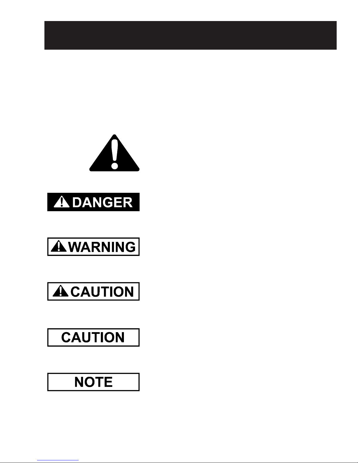
The symbol shown is used to call
your attention to instructions con-
cerningyourpersonalsafety. Watch
for this symbol; it points out impor-
tant safety precautions. It means
"ATTENTION","WARNING","CAU-
TION", and "DANGER". Read the
message and be cautious to the
possibility of personal injury or
death.
SAFETY ALERT SYMBOL
Thank you for choosing a GSI/Air-
streamproduct.Itis designedtogive
excellentperformanceandservicefor
many years.
Thismanualdescribestheinstal-
lation and operation of the Grain
Spreader. It is designed to spread
grainandfinesevenlythroughoutthe
bin.
Theprincipalconcernof the GSI
Group,Inc.("GSI") isyoursafetyand
the safety of others associated with
grain handling equipment. This
manual is written to help you under-
standsafeoperatingprocedures,and
some of the problems that may be
encounteredbythe operatororother
personnel.
As owner and/or operator, it is
your responsibility to know what re-
quirements,hazards andprecautions
exist, and to inform all personnel
associated with the equipment, or
whoareinthearea. Avoid any alter-
ations to the equipment. Such alter-
ations may produce a very danger-
oussituation,whereserious injuryor
death may occur.
GSI DOES NOT WARRANT ANY ROOF DAMAGE CAUSED
BYEXCESSIVEVACUUMORINTERNALPRESSUREFROM
FANS OR OTHER AIR MOVING SYSTEMS. ADEQUATE
VENTILATION AND/OR "MAKEUP AIR" DEVICES SHOULD
BE PROVIDED FOR ALL POWERED AIR HANDLING SYS-
TEMS.GSIDOESNOTRECOMMENDTHEUSE OF DOWN-
WARDFLOWSYSTEMS(SUCTION).SEVEREROOFDAM-
AGE CAN RESULT FROM ANY BLOCKAGE OF AIR PAS-
SAGES. RUNNING FANS DURING HIGH HUMIDITY/COLD
WEATHER CONDITIONS CAN CAUSE AIR EXHAUST OR
INTAKE PORTS TO FREEZE.
SUPER SPREAD GRAIN SPREADER OPERATION

7
SAFETY ALERT DECALS
GrainSystems,Inc.recommends
contactingyourlocalpowercompany,
and having a representative survey
your installation so the wiring is com-
patible with their system, and ad-
equatepowerissuppliedtoyourunit.
Safetydecalsshouldbereadand
understoodbyallpeopleinthe grain
handling area. The bottom right de-
cal should be present on the inside
bin door cover of the two ring door,
24"portholedoorcoverandtheroof
manwaycover.
Ifadecalisdamagedorismiss-
ing contact:
Grain Systems, Inc.
1004 E. Illinois St.
Assumption, IL 62510
217-226-4421
Afreereplacementwillbesenttoyou.

8
ASSEMBLY INSTRUCTIONS
Figure 1: Spreader cone assembly and blade assembly connection.
1. Carefully unpack the unit and
inspectfor shipping damage.
2. Check tightness of all bolts in
theconeandbladeassemblies.
3. Removebladeextensionfrom
bladeassemblyfor 24-footdiam-
eterbinsandsmaller (Figure2).
HARDWARE LIST FOR SPD-2073 & SPD-2074
Part #Item #
SPD-2008
SPD-2010
S-4276
S-1147
S-396
S-845
S-6078
S-6079
*
00405341
11
12
23
28
29
31
33
34
37
DescriptionQuantity
3
3
12
38
34
28
2
1
1
1
Hanger Extention
Hanger Bracket
5/16-18 x 1 1/4" N. F. T. Bolt, grade 5
5/16" Lockwasher
5/16"-18 Hex Nut
5/16" Flatwasher
5/16"-18 x 1/4" Set screw
1/4" x 1" Roll Pin
3/8" Eyebolt
Danger Decal
1/4" Set Screw
1/4" x 1" Roll Pin
1/4" Set Screw
Cone Assembly
Blade Assembly
Item # refers to parts list on page 10 and assembly drawing on page 11.
The Scattergrain is a direct drive
spreader. The unit is powered by a
totally enclosed,1 HP motor. Two
types of motors are offered with the
superspread.Onehasasinglephase
motor (FFD-200-1) and the other
model(FFD-200-3)hasathreephase
motor. Maximum grain capacity is
4,000to6,000bushelsperhour,de-
pendingonmoisturecontent, weight
andfines evenly throughout the bin.
Thiswillhelpprevent uneven drying.

9
ASSEMBLY INSTRUCTIONS
6. Turn thethreespreaderdiverters
outward(Figure2).The diverters
onthebladeassemblyareturned
inward for shipping purposes.
Further adjustments may be re-
quired after installation.
7. Use two 5/16"-18 x 1.1/4" bolts,
four5/16"flatwashers,two 5/16"
lockwashers, and two 5/16"-18
nuts to fasten each of the three
hanger brackets inside the
spreader cone (Figure 3). The
five mounting slots provided in
thehangerbrackets areusedfor
adjusting the spreader up and
down inside the bin. Location is
dependent on several factors
suchasinterferencewith stirring
systems and grain bouncing off
spreader motor onto bin roof.
8. Measure binopening(hatchcol-
lar) toselectcorrectslotsforbolt-
ing hanger extensions to hanger
brackets. All GSI bins with stan-
dard peak roof cap have a hatch
collar diameter 31.1/2". Loosely
mount each hanger extension to
a hanger bracket, using the ap-
propriate slots with two 5/16"-18
x 1.1/4" bolts, two 5/16" lock-
washers, four 5/16" flatwashers,
andtwo5/16"-18nuts(Figure 3).
9. Add 3/8" eyebolt to the top of
motor.
10. Compare assembled unit with
parts assembly drawing (page
11)tomakecertainthatallparts
are properly installed.
Turn spreader diverters
SPD-2003
Note: Remove blade extention
(SPD-2002) for 24' & smaller bins
Figure 2: The diverter segments on the blade.
Figure 3: The spreader cone connection to the hanger bracket.
Hanger bracket
SPD-2010
Adjustable
5/16" Flatwasher
5/16"-18 x 1.1/4"
Bolt
5/16"-18 Nut
5/16" Lockwasher
5/16"-18 Flatwasher
Figure 4: The hanger bracket connection to the hanger extension.
5/16"-18 Nut
5/16" Lockwasher
5/16" Flatwasher
Hanger bracket
SPD-2010
Adjustable
5/16"-18 x 1.1/4" Bolt
5/16" Flatwasher Hanger extension
SPD-2008

10
PARTS LIST
ITEM #
1
2
3
4
5
6
7
8
9
10
11
12
13
14
15
16
17
18
19
20
21
22
23
24
25
26
27
29
30
31
32
33
34
35
36
37
*Denotes items included in gear box assembly.
All parts are standard except for items 1, 2, 10, 36 & 41.
(See description for applications).
PART #
002-1105-2
002-1088-0
017-1534-1
SPD-2154
TFC-0054
FH-6563
SPD-2151
SPD-2068
SPD-2069
SPD-2070
SPD-2008
SPD-2149
SPD-2062
SPD-2061
SPD-2004
SPD-2063
SPD-2003
SPD-2005
SPD-2171
SPD-2006
SPD-2064
*
S-277
SPD-2109
S-1054
S-456
S-6606
S-3611
S-6076
S-845
S-6606
S-6078
S-6079
S-6077
S-7621
*
SPD-2108
TFH-2104
FH-7001
QUANTITY
1
1
1
1
1
1
1
1
1
1
3
3
2
1
1
1
3
1
1
2
1
1
12
*
4
4
15
34
6
6
5
2
1
2
4
1
1
1
DESCRIPTION
1HP 1-Phase C-Face Motor (special)
1HP 3-Phase C-Face Motor (special)
PinionGear
MIGearBoxWith56CAdapter(069-1304-0)
3/4"Seal-TiteElbow-CSA
3/4" Seal-Tite CSA Approved
3/4" 45 DEG Seal-Tite Fitting
CapacitorBox
CapacitorBox Lid
CapacitorClip
HangerExtension
HangerBracket
Gear Box Mounting Bracket
SpreaderCone
UpperBack-upPlate
SpreaderBlade
SpreaderDiverter
LowerBack-upPlate
DriveShaftWeldment
Damper
BladeExtension
Set Screw
5/16"-18 x 1.1/4" Hex Capscrew, grade 5
SpecialGearboxLubricant
3/8"Lockwasher
3/8"-16 Hex Nut
5/16" x 3/4" Hex HD Bolt (serrated)
5/16"-18HexNut
5/16"-18 x 3/4" Carriage Bolt
5/16"Flatwasher
5/16"-18 x 3/4" Hex HD Bolt (serrated)
5/16"-18 x 1/4" Set Screw
1/4" x 1" Roll Pin
U-Bolt 3/8"-16 x 1"W x 2.1/4" Lg.
10-32 x 3/4" Self Tap Screw
3/8" Eyebolt
1HPSpreader Blade Replacement Kit
EC1216C06Capacitor(1Phase)
OC3020F12Capacitor(1Phase)
FFD-200-1 (1 PH MOTOR) & FFD-200-3 (3 PH MOTOR)

11
PARTS ASSEMBLY
WARNING!
Automatic Reset
Overload Protection
NOTE:Tighten set
screws against flat on
motor shaft
Special Gearbox
Lubricant
Locating holes must be
aligned for proper
operation
Not required for
smaller bins

12
INSTALLATION
The units are shipped with the mo-
tor wires disconnected. Carefully
connect motor wires for desired op-
erating voltage as indicated on the
wiring diagram on page 13. Model
SPD-2073 will be wired for 230V.
The other models will not. Be cer-
tain to use electrical connectors of
adequatesize.Thetablebelowpro-
vides wire size information.
The1HP motorisprotectedwith
aninternalautomaticreset overload.
However, it is advisable to provide
additionalprotectionwithfuseorcir-
cuitbreaker.
The motor should turn the
spreaderbladecounterclockwiseas
viewed from above the unit. If the
three phase unit turns clockwise,
the rotationcanbechanged.
This may be done by interchanging
anytwoofthethreepowerwirecon-
nections. The rotation cannot be re-
versed on single phase unit.
Make sure eyebolt is securely
fastened to motor before installing
spreader.DO NOTSTANDUNDER-
NEATH UNIT WHILE IT IS LIFTED
INTO PLACE.
Full Load Amps
Minimum Wire Size
Copper Wire
50' Run
100' Run
150' Run
200' Run
Aluminum Wire
50' Run
100' Run
150' Run
200' Run
Fuse Size (Slow Blow)
Breaker Size
1 HP Spreader Motor
1750 RPM
1 Phase 3 Phase
110V
9.4
14
12
10
8
12
10
8
6
20
25
230V
4.7
14
14
14
14
12
12
12
12
15
20
208V
3
14
14
14
14
12
12
12
12
10
15
230V
2.8
14
14
14
14
12
12
12
12
10
15
460V
1.4
14
14
14
14
12
12
12
12
5
10

13
INSTALLATION
ELECT.
OIL CAPACITORS
SINGLE PHASE-DUAL VOLTAGE WIRING DIAGRAM
110 VOLTS 230 VOLTS
THREE PHASE-DUAL VOLTAGE WIRING DIAGRAM
208/230 VOLTS 460 VOLTS
•For 110 volts 1, 3 and the extra wire on the capacitor
go to L1.
•4 goes to L2, and 2 and J tie together.
•E from the motor goes to E on the capacitor.
•O from the motor goes to O on the capacitor.
•For 230 volts 1 goes to L1.
•2 and 3 and the extra wire on the capacitor go
together.
•4 goes to L2.
•J is tied off by itself.
•E from the motor goes to E on the capacitor.
•O from the motor goes to O on the capacitor.

14
INSTALLATION
1. Adjust hanger extensions to fit
roof opening and install the
power spread unit.
2. Use the 9/32" hole at the end of
each hanger extension and bolt
hanger extensions to hatch
collar.
3. Then tighten all bolts holding
hanger extensions.
4. Once unit is installed, use a
carpenter's level across the top
of the spreader cone to make
sure it is level in all directions
(Figure 5).
5. Ifrequired, add spacer washers
between hanger brackets and
hanger extensions to level unit
(Figure 6).
Figure 5: Mount spreader and check with level.
Mount unit level inside the bin
Carpenter's level
Grain spreader
Use washers
to level unit
(if required)
Hangerextension
(SPD-2149)
Hanger extension
(SPD-2008)
Figure 6: Use washers to level unit.
The 1HP motor is protected with an
internal automatic reset overload.
Beforeservicing,all powertotheunit
mustbedisconnectedandlockedout
toavoid a possible reset/restart and
seriousinjury.
Beforeconnectingandapplying
power, rotate the spreader blade by
hand to be certain it rotates freely
withoutobstruction.Themotorturns
thespreaderblade counterclockwise
as viewed from above the unit. The
superspreadunitrequires115
or 230 volt 1 PH or 230 or 460 volt
3 phase power supply. The mini-
mum wire size is 14 gauge for runs
up to 200 feet. It is advisable to pro-
vide additional protection such as
15 amp slow blow fuses or 20 amp
circuit breaker. Consult a licensed
electrician for wire size on longer
runs. Regardless of grain type and
bin size, the grain flow must be di-
rectly down (vertical) and centered
(horizontal)withinthespreader cone
(Figure 7). This has to be done to
prevent high and low grain surface
areas from one side of the bin to the
other.
Spreader cone
(SPD-2007)
Grain flow
Figure 7: Grain flow must be
centered within the spreader cone.

15
OPERATING INSTRUCTIONS
The grain spreader blade assembly
has four features for adjusting grain
flow pattern.
1. Tilt is the adjustment of the en-
tire spreader blade, which con-
trolsoverallgrainspreading.Tilt
isadjustedbylooseningthetwo
U-bolts that allow the tipping of
Figure 8: Adjustment of the tilt.
the blade up and down. This
mayvaryaccordingtobindiam-
eter and fill rate (Figure 8).
2. Spreader diverters are used to
increase or decrease grain flow
resistanceoverspreaderblade.
With the diverters straight (Fig-
ure 9) the grain will travel fur-
ther. Angled grain diverters will
reduce the throwing distance.
3. Blade extension is used when
extra throwing distance is re-
quired for larger bins.
4. Dampers are used to control
center filling.
Single spreader diverter
end up for desired grain spread.
Grain Spreader
Tilt
Figure 9: Four features for adjusting the grain flow pattern.
Damper
Spreader Diverters
Spreader Blade
Blade Extension

16
OPERATING INSTRUCTIONS
ADJUSTMENT FOR BIN FILL
PART
Spreader Blade
Spreader Diverter
Blade Extension
Damper
REF #
1
2
3
4
TYPE
Tilt
Single Side
Dual Side
Tilt
Opening
LARGE BIN
36" DIA. AND GREATER
OPERATION/PROCEDURE
Decrease (flatten)/loosen U-
bolts and pivot the blade to
horizontal. Always refer to
single diverter side as gauge.
Decrease (center filling)/
loosen bolts and rotate
diverter clockwise.
Decrease (center filling)/
loosen bolts and rotate
diverters clockwise to direct
flow in line with grain stream.
Increase/loosen bolt and
pivot the extension upward to
maximum allowance in
slotted hole.
Decrease (center filling)/
loosen bolts and pivot
dampers to nearly closed
position.
SMALL BIN
24" DIA. AND LESS
OPERATION/PROCEDURE
Increase/loosen U-bolts and
pivot the blade (single diverter
side) upward.
Increase (center filling)/loosen
bolt and rotate diverter counter-
clockwise.
Increase (center filling)/loosen
bolt and rotate diverters coun-
terclockwise to direct flow
across grain stream.
Remove blade extension.
Increase (center filling)/loosen
bolts and pivot dampers to
almost fully open position.
Ref # refers to Figure 9 on page 15.
1. Rotation is always viewed from
topoftheunitlooking down onto
the blade.
2. Be sure to fully tighten all bolts
after each adjustment is made.
3. These adjustmentsdescribethe
requirements for both extremes
of bin sizes. For bin sizes be-
tween 24' and 36' in diameter
start with intermediate adjust-
ments, then vary slightly as re-
quired.

17
OPERATING INSTRUCTIONS
Figure 10: The gear box assembly showing grease level.
MAINTENANCE
For normal operation, annually
relubricatebothmotorbearingswith
approximately ten drops of 5W-30
oil. The gears of the gear box as-
sembly are lubricated with a special
high temperature, food grade lubri-
cant (SPD-2109) at the time of
manufacturing. The level of grease
in the gear box should be checked
annually and will normally not re-
quire further lubrication unless seal
breakage occurs. After the grease
hassettled to the bottom of the gear
box, the grease level can be
checked. The grease level should
of rotation. If power does not exist,
check for blown fuse or flipped cir-
cuit breaker.
If motor stops operating for no
apparentreason,wait approximately
five minutes for the automatic over-
load protection device to reset and
reattemptoperation.Ifproblemcon-
tinues, check power supply for volt-
ageandcheck blade of unit for free-
dom of rotation.
Ifmotorpinionrequiresremoval
for any reason, it must be properly
installed and located, as shown in
the parts assembly on page 11.
notbemorethan 1/4" belowthevent
plug (Figure 10). It may be neces-
sary to insert a wire through vent
plugholetofindthegreaselevel.The
level also can be checked by remov-
ing motor and viewing grease level
through hole for motor pinion gear.
Inspect seals annually for signs
ofleakage(checkbearingsannually
for tightness).
In the event the motor fails to
start, check power supply to the
motor. If power supply exists and
motor still fails to start, disconnect
power and check blade for freedom
DISCONNECT POWER SUPPLY
BEFOREATTEMPTINGANY TYPE
OF SERVICE. THE MOTOR IS
PROTECTED WITH A SELF-RE-
SETTING OVERLOAD PROTEC-
TION.FAILURE TO DISCONNECT
POWER CAN RESULT IN SERI-
OUS INJURY OR DEATH.
Vent Plug
1/4" Minimum Grease Level
Special Lubricant (SPD-2109)
Spreader Gear Box Assembly
(SPD-2154)

18
TROUBLESHOOTING GUIDE
Probable Cause
Tilt blade downward, decrease bite.
Remove blade extension.
Flatten blade, increase bite, decrease
grain flow to spreader. Add blade
extension.
Level spreader, correct grain flow to
spreader, (never allow grain to flow
into spreader at an angle or off
center).
Trouble
Large doughnut shaped ring
caused by grain hitting high on bin
wall.
Grain is high in center of bin, small
doughnut.
Grain is high on one side of bin.
Spreader blade too flat.
Spreader blade too steep.
Not level, not centered.
CORRECT SPREADING PATTERN
Grain is slightly depressed in the center, grain flow is centered and the spreader is level.

19

20
1004 E. Illinois St.
Assumption, IL 62510
Phone 217-226-4421
Toll Free Fax 888-741-3004
Rev: June 26, 2003
GR A I N CO N D I T I O N I N G SY S T E M S
This manual suits for next models
1
Table of contents
Other GSI Group Spreader manuals
Popular Spreader manuals by other brands

Boss Snowplow
Boss Snowplow VBX 3000 owner's manual

Sno-Pro
Sno-Pro Fast-Cast 550 series owner's manual

matev
matev SPR-H/M 125 IX Original operating manual

New Holland
New Holland 130 Specifications

Meyer
Meyer SEL SERIES Installation and operating instruction manual

PERFORMANCE ADVANTAGE COMPANY
PERFORMANCE ADVANTAGE COMPANY K5024 installation instructions