30303486 Issue 3.04
Features
Fault checking on the power.
Cable checking on the intrinsically safe loop.
Metal cabinet, high water-proof and anti-interference
abilities.
“S”, “G” can activate sounder/sounder strobe
externally.
Description
I-9333 Interface can connect with C-9404(Ex) Sounder
and C-9403(Ex) Sounder Strobe in explosion-proof
system. Receiving the start command from fire alarm
control panel or the closed contact signal from “S”, “G”,
I-9333 Interface will activate explosion-proof devices in
field and transmits the action information to the fire alarm
control panel.
When 24VDC power fault or connection fault between the
interface and field sounder or sounder strobe occurs, it will
send fault signal to fire alarm control panel and illuminate
Fault LED.
Built-in safety barrier, it is a relative device to restrict the
energy to the explosive environment.
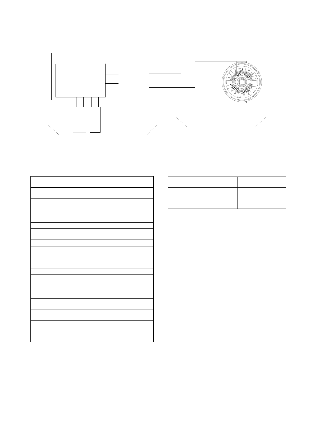
Connection and Wiring
Cable Size
The 1.0mm2 or above intrinsically safe cable is used to
connect safety barrier and explosion proof
sounder/sounder strobe, the capacitance distributed
among cables should not be over 0.083μF, and the
inductance distributed should not be over 4mH. The color
of cables should be different to distinct polarity.
1.0mm2or above copper cable with φ8mm~φ10mm
outer diameter for Z1, Z2, D1, D2, S, and G.
φ8mm~φ10mm cable should be adopted in the places
requiring water-proof. If twisted pair or solid wire has to be
used, twine thread seal tape around the cable going
through the Cable Entry to φ8mm~φ10mm.
Terminals
“Intrinsically safe”side includes terminal 3(+), 4(-) of
safety barrier. 3(+) connects with D1 of explosion proof
sounder/sounder strobe, and 4(-) connects with D2.
Please note polarity.
Note: Must connect the wire correctly otherwise the
interface won’t alarm.
“Non intrinsically safe”side include six terminals. Z1, Z2
connects with the polarity-insensitive loop of fire alarm
control panel, D1, D2 with polarity-insensitive 24VDC
power line and S, G with controlling input contact.
In addition, the enclosure of the interface must connect to
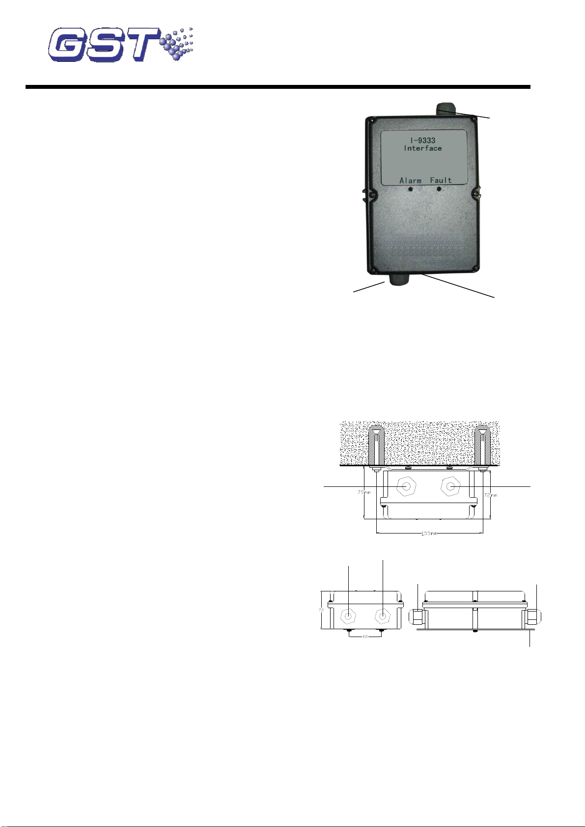
Ground securely, the bolt is as shown in Fig. 1.
Installation
Two mounting methods: One is mounted on the wall, and
the other is mounted on the rack.
a) Wall mounted: Fix the mounting bracket to the wall
using two M6×60 expansion bolts, its mounting dimension
is shown in Fig. 2.
b) Rack mounted: Remove the mounting bracket from the
Fig. 1
back of the interface, then install the interface to the rack
using M4×10 bolts, see Fig. 3.
Warning:This interface should be mounted in safety
area. The wire of the interface from “Non-intrinsically
safe” and those from “Intrinsically safe” should be
separated from each other and be kept a certain
distance (at least 50mm). Strictly follow the relative
explosion-proof code when installing.
Waterproof Cap Cable Entry
Fig. 2
Waterproof Cap
Rack
Cable Entry
Cable Entry
Cable Entry
Fig. 3
Note: Horizontal mounting can protect water
penetrating inside of the interface along the lead.
Application
I-9333 Interface can connect with explosion-proof
sounder/sounder strobe to form explosion-proof system in
fire alarm system. Its wiring diagram is shown in Fig. 4.