22-9240rev2.0 Inovonics Wireless Receiver Installation Instructions 6 / 2009
© 2009 CSG Security Corporation / Société Sécurité CSG Page 4of 6
Guardall
5201 Explorer Drive, Mississauga, Ont., Canada. L4W-4H1
salesna@guardall.com +1 905.206.8434 | supportna@guardall.com +1 905.206.8436 | Fax: +1 905.629.4970
www.guardall.com | +1 877.249.9993
Programming:
Wireless (2) Receiver Module
Compatible with Chubb/Monitor AFx, ISM, xL security
system main panel firmware and Director Software
version 4.1 and greater.
The wireless module learns wireless sensors.
Only Inovonics wireless sensors can be used with the
Inovonics receiver module.
The wireless module does not support wireless keypads
and it is not necessary to reserve input point numbers
for keypad ‘panic’ buttons.
Wireless Receiver Module Programming
The wireless module has a 5-digit module serial
number, which is programmed into the system module
programming. For systems with a Feature Set of 5 or
above, local configuration programming at an LCD
keypad cannot be done. Module enrollment, input point
assigning, must be done using the Director software and
sent to the panel. Wireless transmitter sensors are
learned into the system using the LCD keypad.
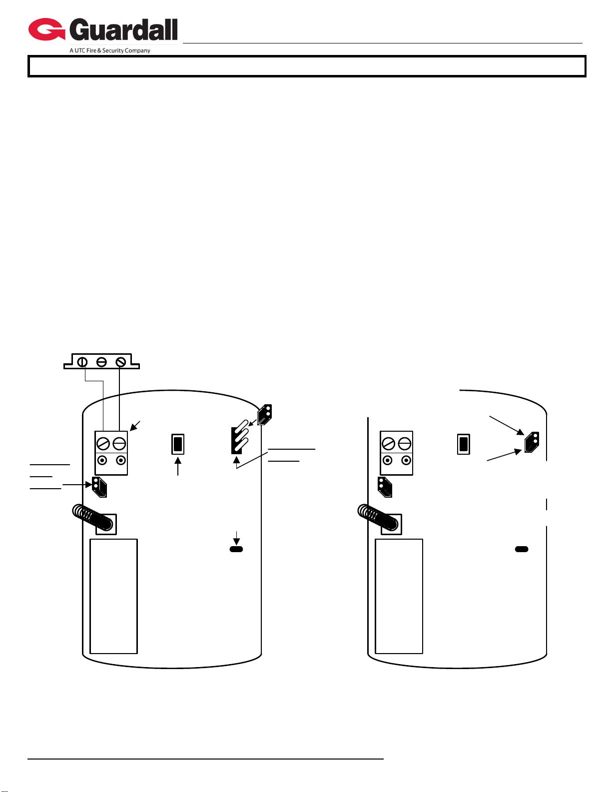
If for some reason the serial number sticker is missing,
the wireless module will display its serial number when it
is first powered. Using the yellow and green Diagnostic
LEDs beside the module bus terminal block, the number
of pulses on the yellow LED while the green LED is ON,
gives the digit value. E.g. green on, count 3 pulses on
yellow, green off, first digit is “3”. Green turns on, yellow
pulses 9 times, green off, second digit is “9”. Etc. etc.
until the entire serial number is displayed, one digit at a
time. It takes several seconds to compete the entire
process. NOTE: “0” is indicated by the green on and NO
pulses of the yellow LED.
Receiver Module Programming
Program the wireless module serial # into the module
configurations. Assign the number of input points
required (4 to 32). The wireless module does not have
outputs. Leave the wireless module’s outputs defaulted
or change them to “0” or none so the outputs can be
assigned some where else. After making these
selections, press the button below ‘Save’ in the LCD
keypad’s module enrollment screen, or send the module
info to the panel from the Director Software.
AllSVN:3 Force:2
Save
The next screen will look
like this. It can only be
programmed through the
system’s LCD keypad. If the module config was sent
to the panel by the Director, go to an LCD keypad
on the system and log on as a service user. Select
‘Config/Advanced’ and the first Module
Configurations screen for this module number: e.g.
M0050. Press the ‘Save’ button from that screen
to get to this one.
AllSVN: Wireless Module Supervision Timeouts. The
time allowed before a supervision signal is transmitted
from the wireless module because it has not received a
trigger or supervisory signal from any of the sensors
assigned to it.
Selections: 1 = 2 Hrs, 15 Min
2 = 6 Hrs, 35 Min
3 = 12 Hrs (default)
4 = 25 Hrs, 15 Min
0 (None) cannot be entered.
Force: The number of times any sensors should be
triggered before the wireless module will Force learn it
into the system. This can be helpful if in a big system
with e.g. wireless PIRs that are being periodically
tripped by people, the force count is increased to avoid
false ‘force’ enrolment of a sensor.
The default is 2 triggers but can be changed from 1 to 9
triggers.
When these selections are acceptable, press the
‘Save’ button. Pressing the button will display the
module type, its input range and its module serial
number.
Repeater Module Programming
No Sensor Learn
Save Rp01
Pressing the Save button
will display the screen for
Repeater Programming.
Rp01 is the Repeater number and Mrepresents
Module Programming.
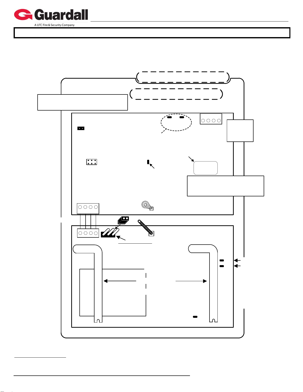
Enroll.R
Stp Tmp Fc
With the Repeater
powered, press the keypad
right arrow key to learn the
Repeater. The Enrollment screen appears. The
tamper switch or reset button on the Repeater’s
circuit board is pressed to assign the Repeater. (see
Enroll.R(press Reset button) Stp (Stop),
Tmp (Tamper) and Fc (Force) descriptions
under the following Input Configuration section.)
SV:0.TM:
Save Del
The screen will change to
the following.
SV is the Supervisory
Timeouts. See the same description and selections
under Input Configuration, (SV:) and enter the
selection with the cursor under the “0”.
TM represents whether the module’s tamper will be
monitored. With the cursor under the ““, press any
key on the keypad to toggle the selection from
tamper enabled to a box ““: no tamper.
Del can be pressed to delete the module.
TFF:0013B2 Edit
Save Rp01
Press Save and the
screen will first display
‘Programming...‘ and
then change to this screen.
TFF:0013B2 is the Repeater’s unique identifying
code.
The right arrow key can be pressed to return to the
previous screen to Edit the Repeater programming or
press Save to proceed to programming another Repeater.