Guest 502-1 User manual

®
®
MODEL 502-1
Spotlight
with joystick control panel
MODEL 503-1
Spot/Flood light
with joystick control panel
MODEL 502-4
Spotlight
INSTALLATION AND OPERATION
INSTRUCTIONS
IMPORTANT!
READ THESE INSTRUCTIONS BEFORE
INSTALLING AND USING THIS PRODUCT.
KEEP THESE INSTRUCTIONS FOR FUTURE REFERENCE.

1
Description
The GUEST 502-1 and 502-4 Spotlights use a 100 watt halogen bulb to produce a tightly
focused beam which can illuminate objects up to 1 mile away.
The GUEST 503-1 Spot/Flood light uses a revolutionary dual-focus halogen bulb. Select
the 100 watt, narrow-beam spotlight for illuminating objects up to 1 mile away or the 55
watt wide-area floodlight for docking and deck lighting.
All Guest Beamer spotlights can rotate 355°and move up and down through an 80°arc.
Models 502-1 & 503-1 come complete with spotlight, joystick control panel, and 15 feet
(4.6m) control cable.
These units are for 12 volt DC use only
#
Tools and additional materials required
Electric drill with 5/16" (7mm) and 1/16" (1mm) drill bits
Wire crimping tool
Screwdriver
2 7/16" (10mm) wrenches
Non-silicon sealant (StarBriteBoat Caulk #83801 or equivalent)
4 1/4" (6mm) Stainless Steel pan or socket head machine bolts
(Bolt length = mounting surface thickness plus 1" (2.5cm)
4 each 1/4" (6mm) Stainless Steel flat washers, lock washers and hex nuts.
4 # 6 x 1/2" (2mm x 1.5cm) Stainless Steel pan head self-tapping screws
1 10 amp fuse and fuse holder
4 10-12 gauge (3-5mm) crimp-on butt connectors
You will also need stranded copper, 2-conductor, 12 gauge (3mm) wire to
connect the spotlight and the control panel to 12 volt DC power sources.
(Use 10 gauge (5mm) wire if the light will be more than 30 feet (9m) from
its power source)
Marine grade plywood.
Installation
Mounting the Spotlight
1. Select a flat, smooth surface to mount the light. Be sure that you will have access to
the underside of the location, and that you can drill holes there without damaging
existing wiring or structures. Avoid locations where lines, anchors, sails or other
hazards might cause damage to the light.

2
NOTE: Mounting the light as far forward or as high as possible can help to reduce
reflected glare when the light is in use.
2. Remove the foam gasket from the base of the light and use it as a template.
Note gasket orientation: Front mounting holes are further apart that the rear holes.
Mark the location of the four corner holes and the center hole squarely onto the
mounting surface with pencil.
3. Drill five 5/16" (7mm) holes through the mounting surface at the marked points.
NOTE: Always wear eye protection when using power tools.
4. Return the foam gasket to the base of the light, making sure that all of the wires exit
through the center hole in the gasket.
5. Feed the wires from the base of the light through the center hole in the mounting
surface. A small amount of a non-silicone sealant, (such as StarBriteBoat Caulk
#83801), can be applied to where the bolts and the wires penetrate the mounting
surface.
CAUTION!
Excessive use of silicone-based sealants may damage the foam gasket or the base of the
spotlight.
6. It is recommended that you use marine grade plywood for a back-plate.
7. Place the light on the mounting surface, lens facing forward, and align the 4 holes
in the light base and the foam gasket with the 4 corner holes drilled into the
mounting surface.
8. Fasten the light securely to the mounting surface using four 1/4" diameter (6mm)
bolts, flat washers, lock washers and nuts. Do not over tighten. Large flat washers
are recommended.
9. Install the gray control cable between the light and the planned location of the
control panel. Avoid running the cable across sharp edges or where it may be
exposed to extreme heat.
Mounting the Control Panel (Models 502-1 & 503-1 only)
1. Select a convenient mounting location for the control panel. Be sure that you will have
access to the area behind the location, and that you can drill holes there without
damaging existing wiring or structures. Do not place the control where it could
interfere with the safe operation of the vessel or vehicle. Avoid mounting the control
panel on a curved surface, or in a location that would be exposed to direct rain or
spray.

3
Control panel mounting
2.25"
1.5"
(57mm)
(38mm)
CAUTION: Always wear eye protection when using power tools!
3. Bring the control cable coming from the spotlight out through the control panel , and
make the connections as shown on page 4 or 5.
4. Feed the spliced cable back into the cutout hole. Test fit the control panel and use a
pencil to mark the locations of the two small holes in the panel onto the mounting
surface. Remove the control panel, then drill a 3/32" (1mm) pilot hole at each of the
marked locations.
5. Apply a small amount of sealant, (such as StarBriteBoat Caulk #83801), to the back
of the control panel face plate. Fit the control panel into the hole, and fasten the
control panel onto the surface with the two Stainless Steel Phillips pan head self-
tapping screws provided w/control.
Electrical Connections
Guest models 502-1, 502-4 and 503-1 lights have two types of wiring connections.
They are:
•
Power supply wires - the larger red (+
++
+) and black (−
−−
−)wires that bring 12 volts DC
power to the light and to the control panel.
•
Control cable wires - the small wires within a gray casing that carry your
commands from the control panel to the spotlight.

4
CAUTION!
DO NOT CONNECT THE POWER SUPPLY WIRES
TO ANY OF THE CONTROL WIRES.
DO NOT REVERSE THE RED (POSITIVE)
AND BLACK (NEGATIVE) POWER WIRES.
This light requires a source of 12 volt DC power that is capable of supplying 10 amps of
current. For best results, run two new wires from the red (+
++
+)positive and black (−
−−
−)
negative power wires of the light directly to the main 12 volt DC accessory panel. Install
fuses as shown in the diagrams on pages 4 and 5. A 10 amp circuit breaker can be
installed instead of an in-line 10 amp fuse.
If the light will be less than 30 feet (9M) from its power source, use 12 gauge (3mm)
wires. If the distance will be more than 30 feet (9M), use 10 gauge (5mm) wires.
Black
12 volts DC
Foam Gasket
10-12 ga. (5mm)
crimp Connector
10 Amp Fuse
(or circuit breaker)
Black
12 volts DC
Red
12 volts DC
1.
Connect the wires from the spotlight cable
to SAME wire colors of provided cable
Male Plugs on
this end of cable
2.
Connect the control cable wires to
SAME wire colors of provided cable
Do not use
blue wires
Red
12 volts DC
10 Amp Fuse
(included)
502-1 Spotlight Wiring Diagram

5
Foam Gasket
10-12 ga. (5mm)
crimp Connector
10 Amp Fuse
(or circuit breaker)
Black
12 volts DC
Red
12 volts DC
1.
Connect the wires from the spotlight
to SAME wire colors of provided cable
Male Plugs on
this end of cable
2.
Connect the control cable wires to
SAME wire colors of provided cable
Black
12 volts DC
Red
12 volts DC
10 Amp Fuse
(included)
503-1 Spot/Floodlight Wiring Diagram
Operation
To move the spotlight, move the joystick gently in the desired direction. The light can be
moved both vertically and horizontally at the same time.
Use the toggle switch to activate the spotlight beam (or the floodlight beam for model
503-1). The 2 spotlights can be moved with the beam switched off.
Precautions
DO NOT look directly into the spotlight or floodlight while it is operating.
DO NOT cover the light with a fabric cover or any other flammable material. Accidental
activation may result in a fire hazard.
DO turn the spotlight toward the control station when not in use. If the spotlight is
accidentally activated during daylight, the operator will be more likely to notice and turn
the spotlight off before draining a battery.

6
Maintenance
Under normal conditions, mild detergent and water will be sufficient to keep the spotlight
clean. Avoid using caustic chemicals or abrasives as they may damage the housing. No
lubrication is necessary.
Replacement Parts (12 volt)
(Available from The Guest Co. See last page for contact information)
Replacement spotlight bulb kit – 502-1, 502-4 729493
Replacement spot/flood bulb kit – 503-1 729494
Joystick control -502-1, 502-4 U-3605
Joystick control - 503-1
Console Control (502-4)
U-3606
U-3128
Lower motor - (502-1, 502-4 and 503-1) U-3135
Upper motor - (502-1, 502-4 and 503 –1) U-3136
Relay - (502-1, 502-4) P-19605
Relay PC board - (503-1) U-3383
Extension Cable Kit (All) 729528
Dual station kit (502-1)
Dual station kit (503-1)
729488
729491
NOTE:
THE CONTROL PANEL USED WITH GUEST MODEL 500 & 501 WILL NOT OPERATE
MODELS 502-1, 502-4 or 503-1.

7
Troubleshooting
Under normal use, your Guest Beamer spotlight will provide you with many years of
reliable service. If your unit should become damaged by a severe impact, we recommend
that you return the unit to our factory for reconditioning.
If an operational problem occurs:
1. Confirm that all fuses are intact. If a fuse has blown, do not replace the fuse until
the cause of the problem has been located and corrected. NEVER replace a blown fuse
with a higher value fuse.
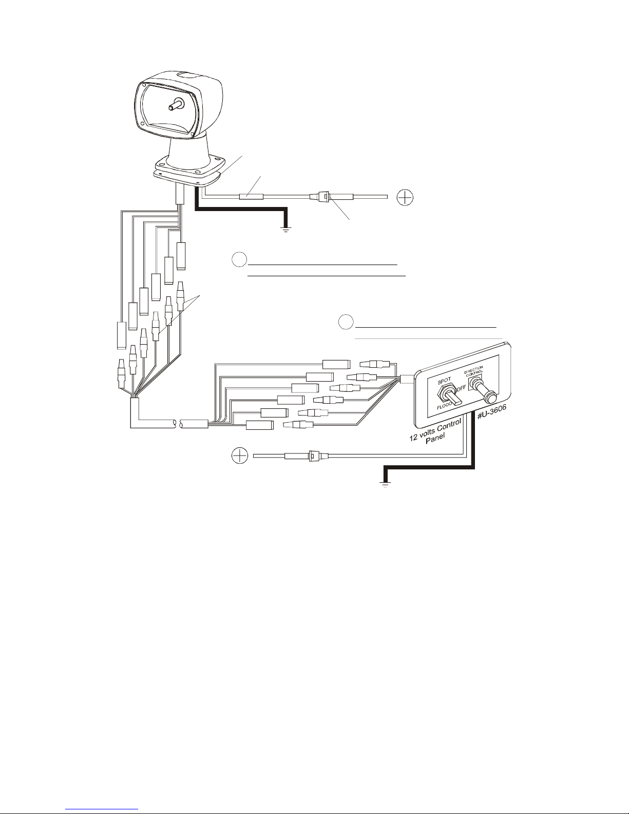
2. Confirm that all wiring connections are accurate and that the spotlight is connected
to a 12 volt DC power source capable of supplying 10 amps even when other
accessories are operating. (See diagrams on pages 4 and 5.)
Check wiring connections, for loose or corroded connections.
MOST PROBLEMS ARE CAUSED BY POOR WIRING CONNECTIONS.
4. If the spotlight does not move or light, remove the 4 bolts that fasten the spotlight
onto the mounting surface and gently lift the light until you can see inside its base.
Avoid cutting any wires. Inspect the visible wiring for loose or broken connections. If
there are signs of water damage, return the spotlight and control to the Guest Service
Department with information about how the spotlight was installed. If there are no
signs of damage, re-install the spotlight and then replace the control pad.
5. If the spotlight moves properly but does not light, examine the halogen bulb.
Replace it if it appears discolored or broken. If the bulb appears normal, test for a
faulty relay by listening at the base of the light while someone activates the bulb from
the control panel. If no "click" is audible, or if a "chattering" sound is heard, return
the spotlight to the Guest Service Department for relay replacement. NOTE: An
inadequate power source may cause similar symptoms.
6. If the spotlight does not move in one direction only (i.e.: up, but not down or left,
but not right), and the connections are good, replace the control panel.
7. If the spotlight will not move left or right but operates normally otherwise, listen at
the base of the light while someone else moves the joystick to the left and right. If the
lower motor makes no sound when it is activated, replace the lower motor.
If your light has a problem that is not described above, return the unit to the Guest Service
Department for a free examination. Be sure to include a brief description of the problem,
proof of purchase (if requesting warranty service), and your daytime telephone and/or fax
number.

8
729570 REV C
LIMITED WARRANTY
For one (1) year from the date of purchase, The Guest Co. will, at its' discretion, repair or
replace for the original consumer, free of charge, any part or parts found upon
examination by Guest Co., 95 Research Parkway, Meriden, Connecticut, USA to be
defective in material or workmanship or both. All transportation charges under this
warranty must be borne by the consumer.
Proof of purchase is required. Proof of purchase must be computerized receipt.
Handwritten receipts not accepted.
THERE IS NO OTHER EXPRESSED WARRANTY. IMPLIED WARRANTIES,
INCLUDING THOSE OF MERCHANTABILITY AND FITNESS FOR A
PARTICULAR PURPOSE, ARE LIMITED TO ONE YEAR FROM THE DATE OF
PURCHASE. THIS IS THE EXCLUSIVE REMEDY AND CONSEQUENTIAL
DAMAGES ARE EXCLUDED WHERE PERMITTED BY LAW.
TECHNICAL CUSTOMER SERVICE
Hours M-F, 9:00 am – 4:00 pm ET
The Guest Company
95 Research Parkway
Meriden, CT 06450
USA
(203)-235-4421
(203)-235-0039 fax
www.guestco.com - website
info@guestco.com - e-mail
This manual suits for next models
2
Table of contents
Other Guest Spotlight manuals
Popular Spotlight manuals by other brands

LightPro
LightPro Onyx 30 Manual and safety instructions

Philips
Philips 579254816 Specifications

GIESSE
GIESSE S10L Use and installation manual

Larson Electronics
Larson Electronics LED10W-1SCB instruction manual

Domus
Domus MURO-15S Series installation manual

Larson Electronics
Larson Electronics The LE-9 Series instruction manual

Clas Ohlson
Clas Ohlson XH-B01013 quick start guide

Vision & Control
Vision & Control SLB-500-R625-P-24V Instructions for use

Seto
Seto ALDEBARAN RAPTOR RP LED Series Instructions for use

Larson Electronics
Larson Electronics GAU-LTL-500W-LED-IR instruction manual

SLV
SLV 1001464 instruction manual

Draper
Draper RLEDL3WB Instructions for