Guinaz R3660 User manual

REV.0 CODE G503155E
*G503155E*
MULTI-FUNCTION DIGITAL
BUS ADAPTOR
REF. R3660
INSTALLATION GUIDE

PAGE 2 REV.0 CODE G503155E
INDEX:
1. INTRODUCTION 3
2. FUNCTIONAL SPECIFICATIONS 3
3. GENERAL CONNECTIONS SCHEMATIC 3
4. OPERATING MODES 4
4.1 Activation of the adaptor relay on receiving a call from a dwelling. 4
4.2 Activation of the adaptor relay when the street panel generates a call to any
dwelling.
4
4.3 Activation of the adaptor relay when the door lock is released. 4
4.4 Activation of the adaptor relay when the street panel camera is activated. 5
4.5 Door opening when the external pushbutton/contact is operated. 6
4.6 Activation of video monitoring when the external pushbutton/contact is
operated.
6
4.7 Generation of a call to a dwelling when the external pushbutton/contact is
operated.
6
4.8 Generation of a call to the porter’s unit when the external
pushbutton/contact is operated.
7
4.9 Immediate door opening on receiving a call from a dwelling. 8
4.10 Adjustable electronic timer. 9
4.11 Remote operation of the relay in a second R3660 adaptor.
A
larm and panic
button applications.
9
5. SETTING THE R3660 ADAPTOR ACTIVATION TIME 11
6. R3660 ADAPTOR CONFIGURATION - GENERAL 11
7. OPENING AND CLOSING THE R3660 ADAPTOR 12
8. INSTALLATION STANDARDS 12

REV.0 CODE G503155E PAGE 3
1. INTRODUCTION
The R3660 multi-function digital bus adaptor is used to provide additional functions in Guinaz digital system
installations. These additional functions are used-configurable. Both the event that produces the activation and the
way of responding to the event can be configured as well as the manner of returning the device to its rest state.
Basically, the adaptor has two activation modes:
By message detection: The adaptor is activated from the digital bus by a command detected by the device.
By external pushbutton detection: The adaptor is activated by an external pushbutton connected to it.
In both cases, the adaptor can behave in two ways:
Activating the internal relay. This option is used to activate elements external to the installation (lights,
sirens, etc) when a call is made to a dwelling, when a door is opened, etc. The relay disconnection is user-
configurable.
Sending a command over the digital bus so that another device in the installation carries out the requested
function (video monitoring, door opening, etc).
2. FUNCTIONAL SPECIFICATIONS
Physically, the adaptor is connected to the digital bus by the terminals called 1M, 2M and 3M. There are two more
terminals for connecting an external pushbutton and three more for the internal relay contacts. It also has three groups
of internal micro switches for configuring its operation as well as a potentiometer to set the activation time.
Adaptor power supply (1M, 2M): 17 V DC, 30 mA
3M terminal: Digital system data line.
Relay: NO, COM, NC Power free contacts
Maximum current: 2 A (250 V AC)
2 A (30 V DC)
EXT. INPUT: Power free contact
Maximum voltage: 25 V
Maximum current: 40 mA
Time range adjustable with the potentiometer: this can be between 1-15 seconds or 0-5 minutes, depending on
how the switches are configured.
3. GENERAL CONNECTIONS SCHEMATIC
R3660
BUS
2M
COM
NC
NO
3M
1M
2M 3M1M
DIGITAL BUS
RELAY
CONTACTS
EXTERNAL
PUSHBUTTON

PAGE 4 REV.0 CODE G503155E
4. OPERATING MODES.
The following describes the configuration of various operating modes for the R3660 adaptor.
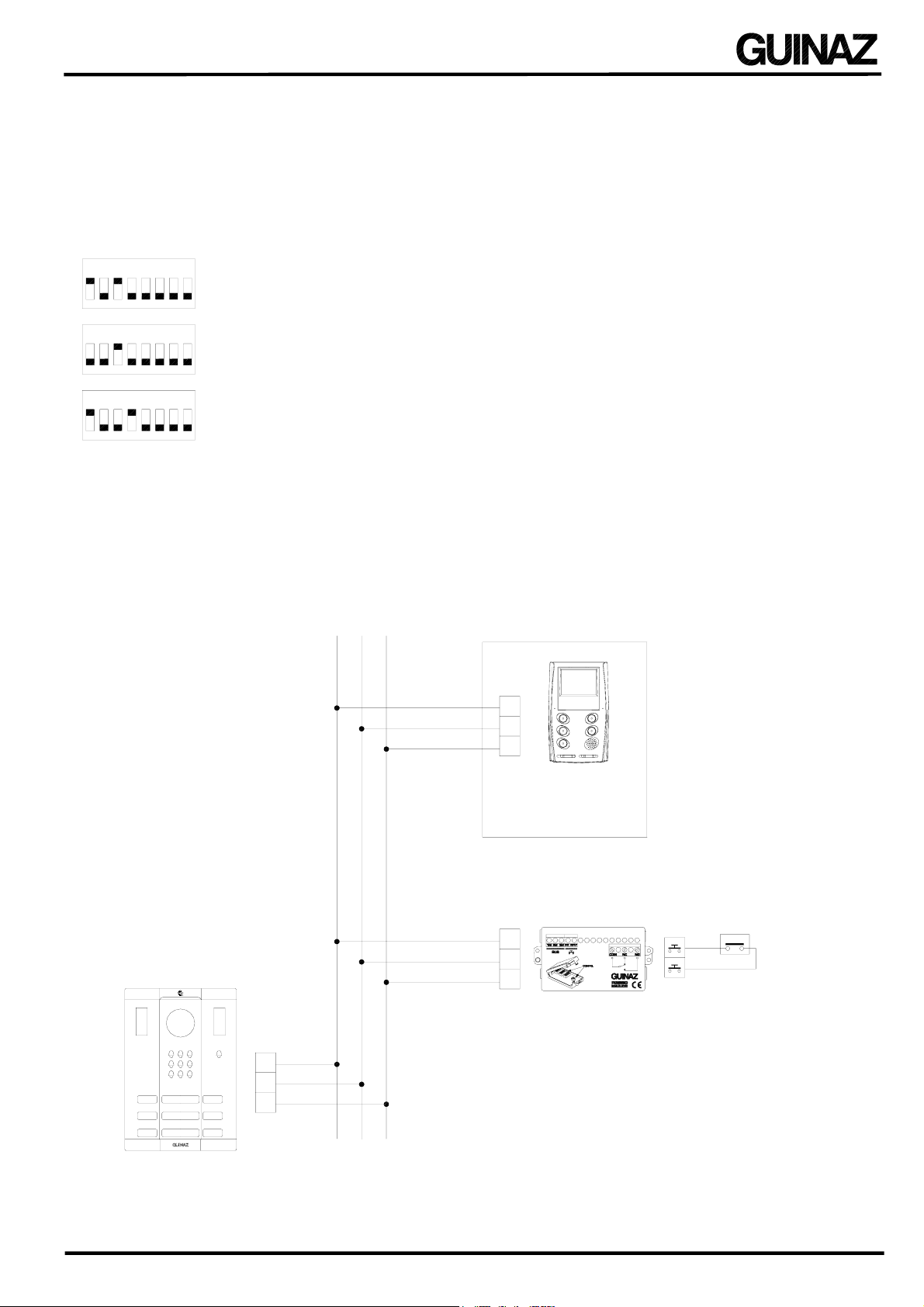
4.1 ACTIVATION OF THE ADAPTOR RELAY ON RECEIVING A CALL FROM A DWELLING
This operating mode activates the R3660 adaptor output relay when it detects that a dwelling is receiving a call. Thus,
for example, a warning light or a siren, external bell, etc, can be switched on to increase awareness of the call. The
configuration for this is as follows:
SWITCH A: configured with the dwelling number (in the diagram, dwelling number
5). It can also be configured with its own number, without needing to be
associated with a dwelling.
SWITCH B: switches 3 and 4 must be configured in the ON position. The rest must
remain OFF. If the adaptor is not associated with any dwelling (number configured
in switch A), switch 5 must be set to the ON position (main).
SWITCH C: switches 1, 2, 3, 4 and 5 must be configured to the OFF position. The
positions of switches 6, 7 and 8 define the end of the relay activation (see section 5).
In the diagram, it ends by time in the range 1 to 15 seconds, adjustable with the
potentiometer.
The connections diagram for this operating mode is shown in FIGURE 1 (page 5).
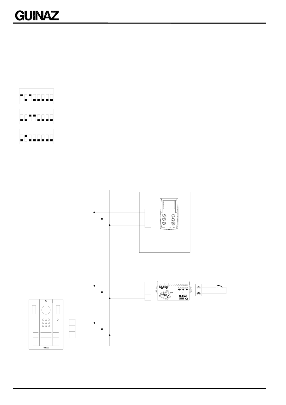
4.2 ACTIVATION OF THE ADAPTOR RELAY WHEN THE STREET PANEL GENERATES A CALL TO
ANY DWELLING
In this configuration any external element can be activated, such as a camera, a lift call, auxiliary lighting, a siren, etc,
when a call is made from the street panel to any dwelling. The R3660 will activate the output relay when it detects a
call being made from the street panel defined in the configuration. The configuration is:
SWITCH A: configured with the street panel number (in the diagram, street panel
number 1).
SWITCH B: switches 2 and 3 must be set to the ON position. The rest must remain
OFF.
SWITCH C: switches 1, 2, 3, 4 and 5 must be set to the OFF position. The positions
of switches 6, 7 and 8 define the end of the relay activation (see section 5). In the
diagram, it ends by time in the range 0 to 5 minutes, adjustable with the potentiometer
The connections diagram for this operating mode is shown in FIGURE 1 (page 5).
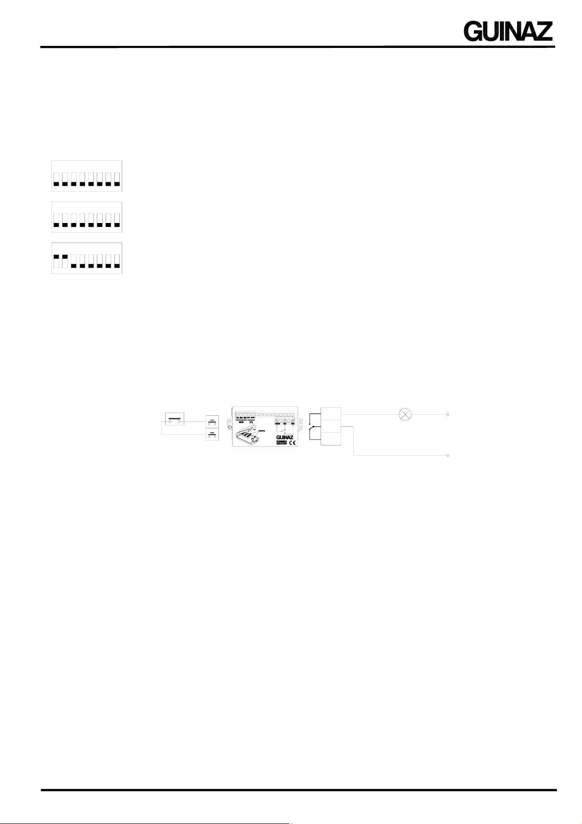
4.3 ACTIVATION OF THE ADAPTOR RELAY WHEN THE DOOR LOCK IS RELEASED
This configuration allows the activation of external elements such as an automatic door, an auxiliary light, etc, when
the street panel receives the order to open the door. The switches must be set as follows:
SWITCH A: configured with the street panel number installed in the access (in the
diagram, panel number 1).
SWITCH B: switches 2, 3 and 4 must be in the ON position. The rest must remain
OFF.
SWITCH C: switches 1, 2, 3 and 4 must be set in the OFF position and switch 5 in
the ON position. The positions of switches 6, 7 and 8 define the end of the relay
activation (see section 5). In the diagram, it ends by time in the range 0 to 15
seconds, adjustable with the potentiometer.
The connections diagram for this operating mode is shown in FIGURE 1 (page 5).
3
SWITCH A
12 78645
12
SWITCH B
35687
12
SWITCH C
3456 87
4
3
SWITCH A
12 78645
12
SWITCH B
35687
12
SWITCH C
3456 87
4
3
SWITCH A
12 78645
12
SWITCH B
35687
12
SWITCH C
3456 87
4

REV.0 CODE G503155E PAGE 5
4.4 ACTIVATION OF THE ADAPTOR RELAY WHEN THE STREET PANEL CAMERA IS ACTIVATED
This configuration is used, for example, to light the area covered by the camera with an auxiliary lights while the
camera is active. The switches are set as follows:
SWITCH A: configured with the street panel number (in the diagram, street panel
number 1).
SWITCH B: must be switches 2, 3 and 4 must be in the ON position. The rest must
remain OFF.
SWITCH C: switches 3, 5 and 8 must be in the ON position and the rest set to the
OFF position. The positions of switches 6, 7 and 8 define the end of the relay
activation (see section 5), in this case when the camera is switched off (end of
communication).
The connections diagram for this operating mode is shown in FIGURE 1 (page 5).
FIGURE 1: Connections schematic for the operating modes explained in sections 4.1, 4.2, 4.3 and
4.4.
R3660
BUS
2M
COM
NC
NO
3M
1M
2M 3M1M
220Vac
1M 2M 3M
3M
1M
2M
3M
1M
2M
DIGITAL BUS
MONITOR OR
TELEPHONE
RELAY
CONTACTS
Auxiliary light,
siren, etc.
(Configure switches according to operation mode)
DIGITAL BUSSTREET PANEL
3
SWITCH A
12 78645
12
SWITCH B
35687
12
SWITCH C
3456 87
4

PAGE 6 REV.0 CODE G503155E
4.5 DOOR OPENING WHEN THE EXTERNAL PUSHBUTTON/CONTACT IS OPERATED
This operating mode allows the door to be opened from a remote location without the need to use the monitor or
telephone in the dwelling; for example, from an external pushbutton or from any electrical/electronic device such as a
motion detector, smoke or fire detector, etc. The configuration for this is:
SWITCH A: configured with the number of the dwelling in which the adaptor is
installed (in the diagram, dwelling number 5). If the adaptor is installed in a location
common to various dwellings, it must be configured with a number different to any of
them.
SWITCH B: switch 3 must be set in the ON position. The rest must remain OFF
SWITCH C: switches 1 and 5 must be in the ON position and the rest must be OFF.
The connections diagram for this operating mode is shown in FIGURE 2 (page 7).
4.6 ACTIVATION OF VIDEO MONITORING WHEN THE EXTERNAL PUSHBUTTON/CONTACT IS
OPERATED
This configuration allows the video monitoring to be activated from a remote point without the need to use the monitor
to see the image from the camera in the street panel in external equipment such as a TV or computer screen. A
pushbutton or the output from any electrical/electronic device must be connected to the input of the R3660 adaptor.
When this input is activated, the adaptor will send an order to the street panel to turn on the video monitoring. The
video signal cabling must lead to the equipment on which the video image is to be seen. The adaptor must be
configured as follows:
SWITCH A: configured with the number of the dwelling in which the adaptor is
installed (in the diagram, dwelling number 5).
SWITCH B: switch 3 must be in the ON position. The rest must remain OFF.
SWITCH C: switches 1, 4 and 5 must be set to the ON position and the rest must be
OFF.
The connections diagram for this operating mode is shown in FIGURE 2 (page 7).
4.7 GENERATION OF A CALL TO A DWELLING WHEN THE EXTERNAL PUSHBUTTON/CONTACT IS
OPERATED
This operating mode is useful to advise a dwelling with a call from a pushbutton or contact external to the entry
system. Any type of electrical/electronic device may be used, such as motion detectors, smoke and fire detectors, etc.
It can also be used to advise on the arrival of a visitor via an access without a street panel or for any other type of
warning, alarms, etc. The adaptor must be configured as follows:
SWITCH A: configured with the number of the dwelling to be called (in the
diagram, dwelling number 5).
SWITCH B: switches 3 and 4 must be in the ON position. The rest must remain
OFF.
SWITCH C: switch 1 must be set to the ON position and the rest must be OFF.
The connections diagram for this operating mode is shown in FIGURE 2 (page 7).
3
SWITCH A
12 78645
12
SWITCH B
35687
12
SWITCH C
3456 87
4
3
SWITCH A
12 78645
12
SWITCH B
35687
12
SWITCH C
3456 87
4
3
SWITCH A
12 78645
12
SWITCH B
35687
12
SWITCH C
3456 87
4

REV.0 CODE G503155E PAGE 7
4.8 GENERATION OF A CALL TO THE PORTER’S UNIT WHEN THE EXTERNAL
PUSHBUTTON/CONTACT IS OPERATED
As in section 4.7, this operating mode is to advise from a pushbutton or contact external to the entry system, but in this
case the porter’s unit is advised instead of a dwelling. Likewise, any type of electrical/electronic device may be used,
such as motion detectors, smoke and fire detectors, etc. It can also be used to advise on the arrival of a visitor via an
access without a street panel or for any other type of warning, alarms, etc.
The adaptor must be configured as follows:
SWITCH A: is configured with a number other than those assigned to the
dwellings in the installation (in the diagram, number 5).
SWITCH B: switch 3 must be in the ON position. The rest must remain OFF.
SWITCH C: switches 1 and 4 must be set to the ON position and the rest must be
OFF.
The connections diagram for this operating mode is shown in FIGURE 2 (page 7).
FIGURE 2: Connections schematic for the operating modes explained in sections 4.5, 4.6, 4.7 and
4.8.
R3660
BUS
2M
3M
1M
2M 3M1M
1M 2M 3M
3M
1M
2M
3M
1M
2M
DIGITAL BUS
DIGITAL BUS
MONITOR OR
TELEPHONE
STREET PANEL
EXTERNAL
PUSHBUTTON/CONTACT
(Configure switches according to operation mode)
3
SWITCH A
12 78645
12
SWITCH B
35687
12
SWITCH C
3456 87
4

PAGE 8 REV.0 CODE G503155E
4.9 IMMEDIATE DOOR OPENING ON RECEIVING A CALL FROM A DWELLING
This configuration opens the door next to the street panel when the dwelling receives a call.
This operating mode is especially practical for offices and surgeries where the door needs to be opened automatically
to anyone who presses the relevant button on the street panel. This function can be cancelled by short circuiting with
the EXT. INPUT switch on the R3660 adaptor, for example, so that the adaptor is inactive outside office hours.
For this operating mode, the switches must be set as follows:
SWITCH A: configured with the number of the dwelling in which the adaptor is
installed (in the diagram, dwelling number 5). It can also be configured with its
own number, without needing to be associated with a dwelling
SWITCH B: switches 3 and 4 must be set to the ON position. The rest must remain
OFF. If the adaptor is not associated with any dwelling (number configured in
switch A), switch 5 must be in the ON position (main).
SWITCH C: switch 2 must be in the ON position and the rest must be OFF.
FIGURE 3: This figure shows the connections schematic for the operation mode explained in
section 4.9.
R3660
BUS
2M
3M
1M
2M 3M1M
1M 2M 3M
3M
1M
2M
3M
1M
2M
DIGITAL BUS
DIGITAL BUSSTREET PANEL
MONITOR OR
TELEPHONE
EXTERNAL
SWITCH
DEVICE STATE:
Switch Open ------ ACTIVE
Switch Closed ---- INACTIVE
(Configure switches according to operation mode)
3
SWITCH A
12 78645
12
SWITCH B
35687
12
SWITCH C
3456 87
4

REV.0 CODE G503155E PAGE 9
4.10 ADJUSTABLE ELECTRONIC TIMER
In this operating mode, the adaptor's relay is activated for a specific time when an external pushbutton or contact
connected to its input is operated. In this configuration, the adaptor can be applied in both standard and digital Guinaz
installations and can activate any external element (auxiliary light, door opening, bell, etc).
The switches must be configured as follows:
All the switches in SWITCH A must be OFF.
All the switches in SWITCH B must be OFF.
In SWITCH C, switches 1 and 2 must be set to the ON position. The position of
switch 6 sets the relay activation time (see section 5). The diagram shows a time
range of between 1 to 15 seconds, adjustable with the potentiometer.
FIGURE 4: This figure shows the connections schematic for the operation mode explained in
section 4.10.
R3660
COM
NC
NO
EXTERNAL
PUSHBUTTON/CONTACT
RELAY
CONTACTS
Auxiliary light,
bell, etc.
Vac / Vdc
(Configure switches according to operation mode)
4.11 REMOTE OPERATION OF THE RELAY IN A SECOND R3660 ADAPTOR - ALARM AND PANIC
BUTTON APPLICATIONS
This type of configuration is used so that one R3660 adaptor receives an event or activation and orders a second
R3660 adaptor to activate its output relay. Various adaptors can be installed to form a network, all configured with the
same number (switch A), some operating in transmitter mode (sending the relay activation order) and others as
receivers (activating their relays). Various networks of adaptors can be connected to the same digital bus.
This operating mode can be used to activate an alarm, siren, emergency light, etc, using the so-called panic button.
The first adaptor recognises the pressing of the panic button, which can be an auxiliary button on the monitor, and
sends the second adaptor the order to activate its output relay.
Another application could be the opening of a second door using the auxiliary pushbutton on the monitor without
requiring another wire in the installation.
3
SWITCH A
12 78645
12
SWITCH B
356 87
12
SWITCH C
3456 87
4

PAGE 10 REV.0 CODE G503155E
ADAPTOR IN TRANSMITTER MODE (transmits the relay activation order):
SWITCH A: set to a number between 1 and 255. This number identifies all the
adaptors in the same network (in the diagram, network 1).
SWITCH B: switches 1, 2 and 3 must be in the ON position. The rest must remain
OFF. This is the transmitter mode configuration.
SWITCH C: switches 1, 3, 4 and 5 must be set to the ON position and the rest must
be OFF. Switch 5 sets the action’s priority. In the diagram, the configuration is high priority,
above any other communication on the bus.
ADAPTOR IN RECEIVER MODE (activates its relay):
SWITCH A: set with a number between 1 and 255. This number identifies all the
adaptors in the same network (in the diagram, network 1).
SWITCH B: switches 1, 2, 3 and 4 must be in the ON position. The rest must
remain OFF. This is the receiver mode configuration.
SWITCH C: switches 3, 4 and 5 must be set to the ON position and the rest must be
OFF. The positions of switches 6, 7 and 8 define the end of the relay activation (see
section 5). In the diagram, it ends by time in the range 0 to 15 seconds, adjustable
with the potentiometer.
FIGURE 5: This figure shows the connections schematic for the operation mode explained in
section 4.11.
BUS
2M
COM
NC
NO
3M
1M
2M 3M1M
1M 2M 3M
BUS
3M
1M
2M
NO
NC
COM
DIGITAL BUS
DIGITAL BUS
EXTERNAL
PUSHBUTTON
RELAY
CONTACTS
R3660 (TRANSMITTER)
(Configure switches according to operation mode)
RELAY
CONTACTS
Auxiliary light,
bell, etc.
Vac / Vdc
R3660 (RECEIVER)
(Configure switches according to operation mode)
3
SWITCH A
12 78645
12
SWITCH B
35687
12
SWITCH C
3456 87
4
3
SWITCH A
12 78645
12
SWITCH B
35687
12
SWITCH C
3456 87
4

REV.0 CODE G503155E PAGE 11
5. SETTING THE ADAPTOR ACTIVATION TIME
Some applications require the adaptor to keep its internal relay active for a specific time before switching to the rest
state. This time is configured using switches 6, 7 and 8 in group C and the adaptor’s internal potentiometer.
Switch 6 is used to select between the two timer ranges. The
potentiometer sets the time within the chosen range.
Switches 7 and 8 set the termination mode, that is, how the
relay returns to the rest state. So that termination is by time,
both switches must be in the OFF position.
6. R3660 ADAPTOR CONFIGURATION - GENERAL
This section provides a general description of the use of the three sets of switches to set the various R3660 operating
modes.
SWITCH A
The eight switches are used to set the device number. Depending on
the operation mode, this could be the number of the device associated
with the adaptor (dwelling, street panel, etc) or that of the adaptor itself.
The number can be from 1 to 255.
SWITCH B
Depending on the operating mode,
switches 1, 2 and 3 define the type of
device associated with the adaptor and
switch 4 indicates whether the adaptor is
activated on sending (transmitter) or on
receiving (receiver) a message from the
associated device. Switch 5 sets the
adaptor as either additional or main.
Switch 5 must be set to the ON position
(main) when the adaptor is not associated
with a dwelling. Switches 6, 7 and 8 are
not used.
SWITCH C
Switches 1 and 2 define the
adaptor's activation mode and
response. Switches 3, 4 and 5
define the type of message that
activates or is sent by the
adaptor, depending on its
operation mode. Switches 6, 7
and 8 are used in those
operating modes in which the
adaptor's relay is activated.
Switch 6 defines the relay
activation time range, adjustable
with the potentiometer. Switches
7 and 8 define the type of
termination, that is, the way in
which the relay will return to the
rest state.
1
1
1
23
2
2
3
3
R3660
231
1
1
23
23
123
4
4
5
5
DEVICE TYPE:
Dwelling
Exterior panel
Main interior
panel
Secondary
interior panel
Interior
porter's unit
Exterior
porter's unit
TRANSMITTER/RECEIVER:
Transmitter
Receiver Main
ADDITIONAL / MAIN:
Additional
21
1
1
2
2
12
3
3
3
54
45
45
345
345
345
6
6
87
78
78
345
ACTIVATION MODE:
Detect message,
activate relay
Detect message,
send message
Detect pushbutton,
send message
Detect pushbutton,
activate relay
MESSAGE TYPE:
Call
Door-opener
Call porter's unit
Video
Camera active (call
+ monitoring)
Activation between
adaptors (l. p.)
Activation between
adaptors (h. p.)
ACTIVATION TIME:
0 - 15 seconds range
0 - 5 minutes range
TERMINATION TYPE:
By time (according to time
range set)
End of communication
Any event that occurs in
system
6
6
78
1 2
SWITCH C
3456 87
1 - 15 seconds range
0 - 5 minutes range
By time (according to time
range set)
8
8
421
ON
0++
12
+
1286416 32
64 00++
16
++ =91
123456 87
VALUE ASSIGNED
SWITCH NUMBER

PAGE 12 REV.0 CODE G503155E
7. OPENING AND CLOSING THE R3660 ADAPTOR
In those installations in which cables must be connected to the outputs of the internal relay in the R3660 adaptor, the
device must be opened by removing the two side screws. The cables are inserted through the slot in the inner plastic
protector and are connected to the terminals. The lid is then replaced and closed with the two screws.
8. INSTALLATION STANDARDS
The R3630 multi-function digital bus adaptor must be used only in Guinaz door and video door opening systems. It
must be installed as described in this guide, complying with the current regulations. Only specialised personnel must
carry out internal work to it, always with the power supply disconnected. This device is designed for interior installation
and must not be exposed to water drips or sprays.
Guinaz SL, P El Escopar P2, 31350 Peralta, Navarra, Spain
www.guinaz.com
Table of contents