DUC Hélices FLASH-R User manual

Aérodrome de Villefranche-Tarare (LFHV)
289 Avenue Odette & Edouard DURAND
69620 FRONTENAS - FRANCE
Phone: + 33 (0)4 74 72 12 69
E-mail: contact@duc-helices.com
ISO 9001:2015
TC EASA: EASA P.038
Part 21G EASA: FR.21G.0273
DH_FSH-R_BE_04_A Made in France 06/05/2019
Instruction manual
3-blade propeller
Certified FLASH-R

This instruction manual is to be maintained throughout the life of the propeller.
He may have to evolve. The owner must check with the DUC Hélices company
the latest version being valid applicable to the propeller.
Revision update
Date
Index
Object of modification
09/05/2019
A
Creation
Every amendment in this document made for the latest revision will appear in dark red.
Identification form
Date
Delivery note n°
Owner
Engine/Gearbox
ratio
Aircraft
1st recommended
pitch blade angle
Notes: ..............................................................................................................................................................................
..........................................................................................................................................................................................
..........................................................................................................................................................................................
..........................................................................................................................................................................................
..........................................................................................................................................................................................

ISO 9001: 2015
TCDS EASA: EASA P.038
Part 21G EASA: FR.21G.0273
Certified FLASH-R
3/27
Summary
1. Presentation of the Certified FLASH-R propeller.......................................................................................................4
Description ........................................................................................................................................................41.1.
Characteristics..................................................................................................................................................41.2.
Shielding leading edge in Inconel®....................................................................................................................51.3.
Accessories.......................................................................................................................................................51.4.
Sales references ...............................................................................................................................................51.5.
2. Applications................................................................................................................................................................6
3. Installation precautions..............................................................................................................................................6
4. Components of the Certified FLASH-R......................................................................................................................7
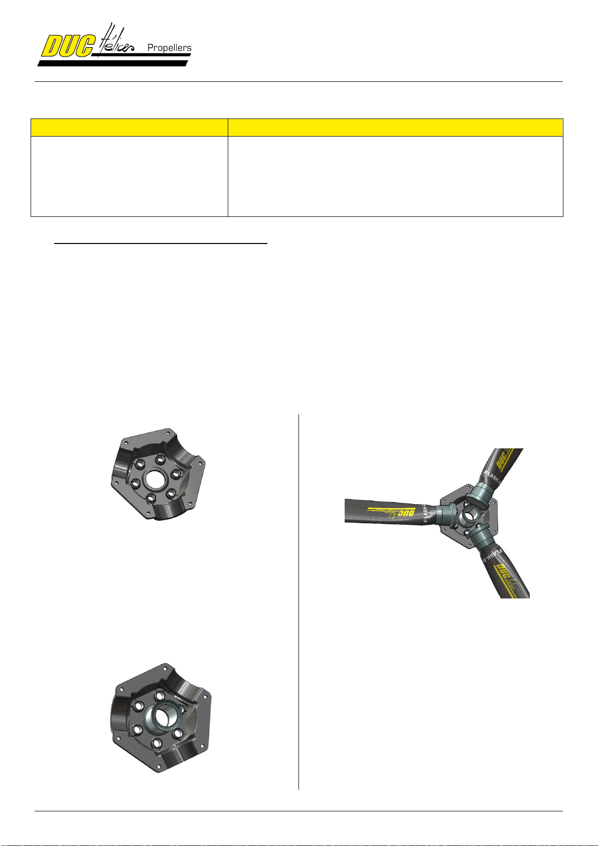
Mounting configuration of the FLASH-R propeller............................................................................................74.1.
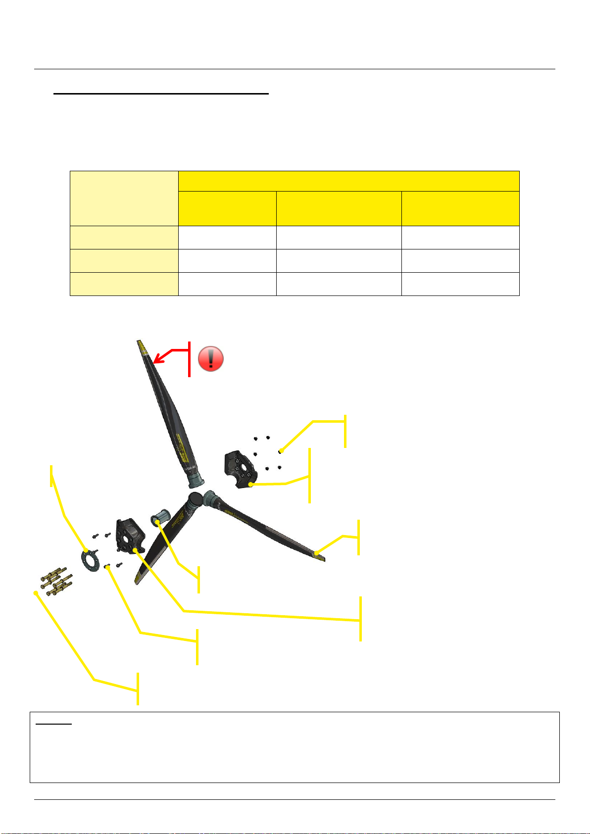
Exploded view for propeller...............................................................................................................................74.2.
List of components............................................................................................................................................84.3.
List of required tools........................................................................................................................................104.4.
5. Assembly instruction of the propeller.......................................................................................................................10
Assembly of the propeller................................................................................................................................105.1.
Installation on the aircraft................................................................................................................................125.2.
Setting of the propeller & Finalization of the installation.................................................................................155.3.
6. Precautions..............................................................................................................................................................18
7. Continuing airworthiness .........................................................................................................................................19
Airworthiness limitations..................................................................................................................................197.1.
Schedule of propeller check............................................................................................................................197.2.
Regular maintenance (by the user).................................................................................................................207.3.
Maintenance of 100 hours or yearly maintenance..........................................................................................217.4.
Impact location on the blade carbon surface ..................................................................................................227.5.
8. General terms of sale...............................................................................................................................................23
Ordering procedure.........................................................................................................................................238.1.
Delivery ...........................................................................................................................................................238.2.
Price ................................................................................................................................................................238.3.
Right of withdrawal..........................................................................................................................................238.4.
Warranties.......................................................................................................................................................23
8.5.
Privacy Policy..................................................................................................................................................238.6.
Litigation..........................................................................................................................................................238.7.
9. Annexes...................................................................................................................................................................24
Dimension of the engine propeller-shaft .........................................................................................................249.1.
912H spacer –Table screw length vs. Spacer thickness .......................................Erreur ! Signet non défini.9.2.
Airfoil ...............................................................................................................................................................259.3.

Certified FLASH-R
4/27
1. Presentation of the Certified FLASH-R propeller
Description1.1.
The certified FLASH-R propeller has a new innovative design,
specific about its twisting axis and center of pressure.
Its aerodynamic design allows a "Constant Speed" effect, limiting
variations in engine speed between on ground and in flight.
This propeller allows high efficiency throughout the flight envelope i.e.:
Improved takeoff and climb rate due to higher engine speed, then higher engine efficiency
Many cruise extension
A high user comforts
The blades and the hub of the FLASH-R propeller are manufactured according the DUC Hélices company
technologies, from unidirectional layers of carbon fibers prepreg epoxy resin.
The blade composite structure is defined to obtain the maximum strength in torsion and bending. Therefore
"constant speed" effect is not related to deformation of the blade but its geometry and specific profile.
Due to its specific geometric definition, excellent performance is obtained in both aerodynamic and acoustic,
but also in consumption.
Characteristics1.2.
The Certified FLASH-R propeller range is available:
Ground adjustable propeller
Tractor configuration available in right rotation
Diameters Ø1520 to Ø1900mm (Ø59.8 to Ø74.7")
Shielded leading edge in Inconel®
Carbon composite hub with metallic inserts
Protected again lightning strike
Direct assembly on the propeller-shaft Ø101.6mm
Safety marking on the tip of the propeller

ISO 9001: 2015
TCDS EASA: EASA P.038
Part 21G EASA: FR.21G.0273
Certified FLASH-R
5/27
Shielding leading edge in Inconel®1.3.
The leading edge of the Certified FLASH-R blades is equipped with a metallic shielding in Inconel®. This material is a
superalloy containing mainly nickel, with a very high hardness of surface.
Accessories1.4.
Aluminum mounting spacer (Direct mounting on P.C.D Ø101.6mm/Ø4”)
Moves the plane of the propeller to adjust the position according the engine hood
Aluminum adaptor spacer (Other mounting as SAE1, SAE2, …)
Move the propeller plane and adaptor the P.C.D fixation of the propeller
Spinner available in diameter Ø250mm (Ø9.8") to Ø340mm (Ø14.4”)
Adjusting tool for the setting of the pitch angle of the blades
Neoprene cover protection of the blade
Cleaning treatment for composite propellers
Save money! A clean propeller is more efficient and decreases the fuel consumption.
Sales references1.5.
Designation
Reference
Part number
Three-blade Inconel FLASH-R Right (ROTAX mounting)
01-40-001
H-FSH_3-D-R_I_RX_C
Three-blade Inconel FLASH-R Right (AN6 mounting)
01-40-011
H-FSH_3-D-R_I_AN6_C
Three-blade Inconel FLASH-R Right (AN8 mounting)
01-40-021
H-FSH_3-D-R_I_AN8_C
Note:
Specify the flight regulation aircraft (E.g.: Ultra-light, LSA…) and diameter when ordering (E.g.: ref. 01-21-001/1730).
Inconel shielding

Certified FLASH-R
6/27
2. Applications
DUC propellers are given for a flight potential under normal operating conditions. To maintain this potential, DUC
Propellers has determined a TBO (time between revisions) for a propeller based on the engine it equips. See the
section 7.1 Airworthiness Limitations for Information Benefit.
Engine
Gearbox
Propellers limits
Propeller diameter
(mm)
Blade angle
(°)
Blade angle
allowed
range (°)
TBO- Time Between
Overhaul*
(hour)
ROTAX 912S
ROTAX 912iS
ROTAX 914
2.43
160 HP
2 700 RPM
Ø1730
24°± 2°
22° → 30°
2 000 hours
or
6 years
Ø1750
24°± 2°
22° → 30°
Ø1800
19°± 2°
17°→25°
Ø1850
19°± 2°
17°→25°
Ø1900
18°± 2°
16°→24°
CONTINENTAL O-200
-
Ø1660
20°± 2°
18°→ 26°
LYCOMING O-235
-
Ø1660
20°± 2°
18°→ 26°
LYCOMING O-320
-
Ø1900
20°± 2°
18° → 26°
* It is the maximum period of propeller use allowed by propeller type certificate.
Compliance with CS-P, Subpart D has not been demonstrated as part of the propeller certification.
Remark
The values of the pitch angle are defined by flight test on each engine. If necessary, this setting should be adjusted
according to the aircraft.
For proper use of the propeller, refer to section 7.Continuing airworthiness
3. Installation precautions
WARNING
Make sure the ignition is turned off before starting any type of operation on the propeller.
Do not run the engine without propeller, engine damage will result
IMPORTANT
The blades of a propeller are part of a whole. DO NOT INTERCHANGE with other similar blades from propeller. The
propeller blades are manufactured to their application. Their structure, weight and balance are different from a propeller
to another.
The spinner is an important element for cooling the engine. The aircraft must not fly without a spinner.
Fitting a different spinner will be an addendum to this manual approved by the DUC to confirm its compatibility with the mounting of
the propeller.
The propeller is delivered with the appropriate screws. The change of the screws is contrary to our recommendations unless
validated by the manufacturers.
WARRANTY CONDITIONS
The user is still flying under its full responsibility (see.8.General terms of sale).

ISO 9001: 2015
TCDS EASA: EASA P.038
Part 21G EASA: FR.21G.0273
Certified FLASH-R
7/27
4. Components of the Certified FLASH-R
Mounting configuration of the FLASH-R propeller4.1.
Here is a configuration table of the three-blade certified FLASH-R propeller mounting according the propeller-shaft of
the engine.
If needed, see annex 9.1 Dimension of the engine propeller-shaft
MOUNTING
ENGINE PROPELLER-SHAFT
Ø4" / Ø101.6mm
(Rotax)
Type SAE1
Ø4-3/8" / Ø111.125mm
(Ex: Continental O-200)
Type SAE2
Ø4-3/4" / Ø120.65mm
(Ex: Lycoming O-320)
direct on propeller-
shaft (without spacer)
X
with spacer
X
with adaptor spacer
X
X
Exploded view for propeller4.2.
Remark
This exploded view shows the principle of the certified FLASH-R propeller assembly. The size of all of these
components changes depending on the configuration of the propeller (diameter hole of the metallic inserts of the half-
hub, length of the screws…).
Inconel FLASH-R
blade right(x3)
Screws & washers
for hub assembly (x6)
Hub camping washer (x1)
Locking nuts & washers
for hub assembly (x6)
Rear half-hub (x1)
with rear metallic inserts (x6)
According to mounting
Fixing screws and washers of the propeller
adapted according the mounting (x6)
Internal hub spacer (x1)
Caution when handling the blades
CUTTING TRAILING EDGE
Front half-hub (x1)
with front metallic inserts (x6)
According to mounting

Certified FLASH-R
8/27
List of components4.3.
Designation
Optional
(According to
the recommend
mounting)
Part Number
Quan
tity
Spacer (optional)
912H spacer - 3mm
X
EI-912H-3
01
912H spacer - 6mm
X
EI-912H-6
912H spacer - 10mm
X
EI-912H-10
912H spacer –15mm
X
EI-912H-15
912H spacer - 20mm
X
EI-912H-20
912H spacer - 45mm
X
EI-912H-30
912H spacer - 30mm
X
EI-912H-45
912H spacer - 60mm
X
EI-912H-50
912H spacer - 30mm
X
EI-912H-60
912H spacer - 70mm
X
EI-912H-70
912H spacer - 75mm
X
EI-912H-75
912H spacer - 80mm
X
EI-912H-80
912H spacer - 100mm
X
EI-912H-100
912H spacer - 120mm
X
EI-912H-120
Dowel spacer DUC Ø13 L20
X
PI-DUC13-20
06
Dowel spacer DUC Ø13 L30
X
PI-DUC13-30
Dowel spacer DUC Ø13 L40
X
PI-DUC13-40
Dowel spacer DUC/ROTAX Ø13 M8 L28
X
PI-RX-28
Dowel spacer DUC/ROTAX Ø13 M8 L30
X
PI-RX-30
Screws CHC M8x40mm
(included pins contact lock washer Ø8mm and Nylstop self-locking nut M8)
X
V-CHC8-40
06
Adaptor spacer (optional)
SAE1-AN6 adaptor spacer - 30mm
X
E-SAE1AN6-30
01
SAE1-AN6 adaptor spacer - 70mm
X
E-SAE1AN6-70
SAE1-AN6 adaptor spacer - 80mm
X
E-SAE1AN6-80
SAE1-AN6 adaptor spacer - 100mm
X
E-SAE1AN6-100
SAE2-AN6 adaptor spacer - 30mm
X
E-SAE2AN6-30
SAE2-AN7 adaptor spacer - 90mm
X
E-SAE2AN7-90
SAE2-AN7 adaptor spacer - 100mm
X
E-SAE2AN7-100
SAE2-AN8 adaptor spacer - 30mm
X
E-SAE2AN8-30
Dowel spacer DUC Ø17 AN6
X
PI-DUC17-AN6
06
Dowel spacer DUC Ø17 AN8
X
PI-DUC17-AN8
Safety washer DUC AN6
X
RS-AN6
Safety washer DUC AN8
X
RS-AN8
Screws 3/8" UNF 1-3/4"
X
V-3/8-1_3/4
06
Screws 1/2" UNF 1-1/2"
X
V-1/2-1_1/2
Screw 3/8" UNF 2-1/2"
X
V-3/8-2_1/2
Screw 3/8" UNF 3"
X
V-3/8-3
Hub
3-blade rear half-hub Certified FLASH-R ROTAX
-
DMFSH-3-AR_RX_C
01
3-blade rear half-hub Certified FLASH-R AN6
-
DMFSH-3-AR_AN6_C
3-blade rear half-hub Certified FLASH-R AN8
-
DMFSH-3-AR_AN8_C
Certified internal FLASH-R hub spacer
-
EMFSH_C
01
3-blade front half-hub Certified FLASH ROTAX
-
DMFSH-3-AV_RX_C
01
3-blade front half-hub Certified FLASH AN6
-
DMFSH-3-AV_AN6_C
3-blade front half-hub Certified FLASH AN8
-
DMFSH-3-AV_AN8_C
Screws CHC M8x30
(Included narrow plain washer Ø8mm and Nylstop self-locking nut M8)
-
V-CHC8-30
06
Certified hub clamping washer FLASH ROTAX
-
RS-FSH-RX_C
01
Certified hub clamping washer FLASH AN6
-
RS-FSH-AN6_C
Certified hub clamping washer FLASH AN8
-
RS-FSH-AN8_C

ISO 9001: 2015
TCDS EASA: EASA P.038
Part 21G EASA: FR.21G.0273
Certified FLASH-R
9/27
Designation
Optional
(According to
the recommend
mounting)
Part Number
Quan
tity
Blade FLASH-R
Certified Inconel FLASH-R blade, Right
-
FSH-D-R_I_C
03
Fixing screws
Screws CHC M8x130
(included pins contact lock washer Ø8mm and Nylstop self-locking nut M8)
-
V-CHC8-130
06
Screws CHC M8x140
(included pins contact lock washer Ø8mm and Nylstop self-locking nut M8)
-
V-CHC8-140
Screws CHC M8x150
(included pins contact lock washer Ø8mm and Nylstop self-locking nut M8)
-
V-CHC8-150
Screws CHC M8x160
(included pins contact lock washer Ø8mm and Nylstop self-locking nut M8)
-
V-CHC8-160
Screws CHC M8x180
(included pins contact lock washer Ø8mm and Nylstop self-locking nut M8)
-
V-CHC8-180
Screws CHC M8x200
(included pins contact lock washer Ø8mm and Nylstop self-locking nut M8)
-
V-CHC8-200
Screws DUC AN6-52
(included washer 960-616)
-
V-AN6-52
Screws DUC AN8-52
(included washer 960-816)
-
V-AN8-52
Accessories: Spinner & Mounting plate
3-blade spinner mounting plate Ø250mm ROTAX
X
P-250_3-RX
01
3-blade spinner mounting plate Ø250mm Ø17
X
P-250_3-17
3-blade spinner mounting plate Ø260mm ROTAX
X
P-260_3-RX
3-blade spinner mounting plate Ø260mm Ø17
X
P-260_3-17
3-blade spinner mounting plate Ø270mm ROTAX
X
P-270_3-RX
3-blade spinner mounting plate Ø270mm Ø17
X
P-270_3-17
3-blade spinner mounting plate Ø290mm ROTAX
X
P-290_3-RX
3-blade spinner mounting plate Ø290mm Ø17
X
P-290_3-17
3-blade spinner mounting plate Ø300mm ROTAX
X
P-300_3-RX
3-blade spinner mounting plate Ø300mm Ø17
X
P-300_3-17
3-blade spinner mounting plate Ø340mm ROTAX
X
P-340_3-RX
3-blade spinner mounting plate Ø340mm SAE1-AN6
X
P-340_3-SAE1AN6
3-blade spinner mounting plate Ø340mm SAE2-AN6
X
P-340_3-SAE2AN6
3-blade spinner mounting plate Ø340mm SAE2-AN7
X
P-340_3-SAE2AN7
3-blade spinner mounting plate Ø340mm SAE2-AN8
X
P-340_3-SAE2AN8
3-blade spinner Ø250mm
X
C-250_3
01
3-blade spinner Ø250mm L
X
C-250L_3
3-blade spinner Ø260mm
X
C-260_3
3-blade spinner Ø270mm
X
C-270_3
3-blade spinner Ø290mm
X
C-290_3
3-blade spinner Ø300mm
X
C-300_3
3-blade spinner Ø340mm
X
C-340_3
Spinner closure plate
X
CC-250_350
03
Spinner screws M5x16mm
X
V-P5-16
09
Spinner screws AN-525-10R8
X
AN-525-10R8

Certified FLASH-R
10/27
List of required tools4.4.
Rotax mounting
SAE1/SAE2 mounting (Lycoming, Continental, …)
6 Torque Allen Wrench (Torque: 25 Nm)
Flat key 13
Inclinometer (angle adjustment tools)
Nylon mallet
Torque screwdriver (Torque: 4 Nm)
6 Torque Allen Wrench (Torque: 25 Nm)
Flat key 13
3/8 or 1/2 Torque Wrench (Torque: 30 to 45 Nm)
Inclinometer (angle adjustment tools)
Nylon mallet
Torque screwdriver (Torque: 4 Nm)
5. Assembly instruction of the propeller
The assembly of the Three-blade Certified FLASH-R propellers is shown below. It is recommended to assemble the
propeller on a worktable before installing it on the plane.
For further information, contact the DUC Hélices Company.
Assembly of the propeller5.1.
A « Propeller Form » will be done to insure a propeller follow-up. Parts Number and component serial number of
propeller will be written on this form.
STEP
1.
Place the rear half-hub on a worktable.
Be careful not to invert with the front hub half.
Depending on your installation, the rear half-hub is one
mounted on the propeller-shaft of the engine or on a
spacer. The diameter of the bore of the metal inserts of
the rear half- hub is larger than the bore of the metal
inserts of the front half-hub.
STEP
2.
Place the hub spacer in the center of the rear half-hub.
STEP
3.
Positioning the blades in their hub slots by placing them
outwards.
The three blades of the propeller have been
balanced at DUC Helices before their dispatch.
Position the DUC Hélices logo facing you.
Note that the metal inserts of the half-hub allow a
locking of the blades in their axis within the hub.

ISO 9001: 2015
TCDS EASA: EASA P.038
Part 21G EASA: FR.21G.0273
Certified FLASH-R
11/27
STEP
4.
Place the front half-hub (metal insert with small hole)
on the set to fit with the blade foots and internal spacer.
STEP
5.
From the front hub, set up the 6 screws and washers
for hub assembly. At the rear, place washers and lock
nuts.
Perform initial moderate tightening.
STEP
6.
Place the hub clamping washer on the front of the
propeller hub (logo side).
Be sure the direction of the clamping washer
(rounded edge outwards).
Place the 6 fixing screws and their washer.
In the case of pin contact washers, the pins are
oriented towards the screw head.

Certified FLASH-R
12/27
Installation on the aircraft5.2.
As presented in section 4.1. Mounting configuration of the FLASH-R propeller, several mountings are possible:
1. Installing directly on propeller-shaft of the engine
2. Use a spacer for spacing propeller from the propeller-shaft
3. Use an adaptor spacer to adjust the diameter fixing of the propeller and for spacing the propeller from the
propeller-shaft
5.2.1. Direct installation on the aircraft
The direct installation of the FLASH-R propeller is possible only with the following conditions:
Engine propeller-shaft type Rotax (6 indexing dowels Ø13 on P.C.D. Ø101.6mm/Ø4")
Engine propeller-shaft out of the engine hood of 14mm for the mounting of the DUC spinner
If needed, see in annex 9.1 Dimension of the engine propeller-shaft.
Remark: All engines having a propeller-shaft with a P.C.D. Ø101.6mm/Ø4" can install the FLASH propeller directly.
The holes of the metal inserts of the rear half-hub must be adapted to suit with the indexing dowels of the
propeller-shaft. For further information, contact the DUC Propellers.
14 mm
min.
5 mm min.

ISO 9001: 2015
TCDS EASA: EASA P.038
Part 21G EASA: FR.21G.0273
Certified FLASH-R
13/27
5.2.2. Use of a spacer
A spacer is necessary in the following case:
Engine propeller-shaft type Rotax (6 indexing dowels Ø13 on P.C.D. Ø101.6mm/Ø4")
Engine propeller-shaft positioned inside the engine hood or positioned at less than 14mm
Determination of the spacer length:
Measure the distance X between the propeller-shaft and the engine hood limit, then add 14mm.
Available spacer:
Engine
Model
P/N
Length (XX)
ROTAX
Spacer 912H
E-912H-XX
3, 6, 10, 15, 20, 30, 45, 50, 60, 70,
75, 80, 100, 120mm
→ The length of the hardware necessary to fix the propeller is defined by the DUC Hélices design office. This is also
the case when it is necessary to set up an intermediate spacer.
→ Tightening screws: see step 7 of § 5.3. Propeller adjustment & Finalizing the assembly.
→ The spacers are delivered with the dowels.
Propeller-shaft not
outside the engine
hood
X
14 mm min.

Certified FLASH-R
14/27
5.2.3. Use of adaptor spacer
An adaptor spacer is necessary in the following case:
Engine propeller-shaft different than the type Rotax (other than P.C.D. Ø101.6mm/Ø4")
If needed, see in annex 9.1 Dimension of the engine propeller-shaft
Determination of the adaptor spacer length:
Measure the distance X between the propeller-shaft and the limit of the engine hood, then add 14mm.
Available adpator spacer:
Engine
Type
Model
Length (XX)
Continental O-200
Lycoming O-233 / 235
Adaptor spacer SAE1 AN6
E-SAE1AN6-XX
30mm
70mm
80mm
100mm
Lycoming O-320 (3/8 dowels)
Adaptor spacer SAE2 AN6
E-SAE2AN6-XX
30 mm
Lycoming O-320 (7/16" dowels)
Adaptor spacer SAE2 AN7
E-SAE2AN7-XX
90 mm
100 mm
Lycoming O-360
Adaptor spacer SAE2 AN8
E-SAE2AN8-XX
30mm
Placing of brake plates under the heads of the fixing bolts of the spacer to prevent the unscrewing of these. (steps
folding 1 → 2 → 3)
→ The length of the hardware necessary to fix the propeller is defined by the DUC Hélices design office. This is also
the case when it is necessary to set up an intermediate spacer.
→ Tightening screws: see step 7 of § 5.3. Propeller adjustment & Finalizing the assembly.
→ The spacers are delivered with the dowels.
Propeller-shaft not
outside the engine
hood
14 mm min.
1
3
2

ISO 9001: 2015
TCDS EASA: EASA P.038
Part 21G EASA: FR.21G.0273
Certified FLASH-R
15/27
Setting of the propeller & Finalization of the installation5.3.
At this point, the propeller is installed on your aircraft with the spinner mounting
plate.
If the propeller is already assembled and the blades angle set, pass directly
STEP 7.
Otherwise, follow all the steps below to adjust the pitch angle before the final
tightening of the screws.
A reminder of the definition of the airfoil and its vocabulary is presented in annex
Erreur ! Source du renvoi introuvable..
STEP 1.
Side view
Front view
For the setting, the concerned blade must be place in horizontal position.
The setting is done with the adjusting tool flatten against the intrados (leading edge up) at 25 cm from the blade tip.
The angle of attack is formed by the vertical and the intrados of the blade.
To do this, place your aircraft horizontally, so that the propeller mounting flange is perfectly vertical.
Check with the level of the adjustment tool (measured value = 90°). If unable to change the longitudinal axis of the
aircraft, raising the value of the Xangle propeller shaft plate to subtract the value of the blade angle to be
resolved.
90°
Propeller-
shaft plate
0°
90°
(90° - X)
25 cm

Certified FLASH-R
16/27
STEP 2.
Slightly untighten the propeller fixing screws
and the hub assembly screw.
STEP 3.
Horizontal blade, leading edge upward, place the adjustment tool at 25 cm from the tip of the blade, intrados
side (flat), handle down.
STEP 4.
Set the desired value of the adjustment tool.
Caution to apply the value Xif a correction of the aircraft plan was needed.
STEP 5.
Correct the position of the bubble on the adjustment tool by rotating the blade in the hub. To do this, using a mallet,
lightly tap on the foot of the blade in the desired direction.
Do not apply pressure near the trailing edge, thinner area.
Adjustment roller of the
angle of attack
Reading blade angle
Intrados of the blade with the
leading edge upwards
Horizontal blade
25 cm

ISO 9001: 2015
TCDS EASA: EASA P.038
Part 21G EASA: FR.21G.0273
Certified FLASH-R
17/27
TIGHTENING TORQUE
2,5 Kg/m 25 N.m
STEP 6.
Once the desired pitch angle obtained, slightly tighten the assembly screws of
the hub, those around the foot blade and then perform the same operation on
each of the other blades.
STEP 7.
Remove the adjusting tool from the propeller then perform a first tightening of the bolts manually.
Then, carry out a progressive tightening of all the screws by applying the correct torque with a torque wrench:
Mounting with a 912H spacer:
Assembly of the three-blade hub + Fixation of the
spacer (EI-912H-80, 100, 120):
(screw length adapted according the adaptor spacer
length and the starter flange on the propeller-shaft)
Propeller fixing: (or spacer if spacer > 80mm)
Screw CHC M8 & pin contact washer (screw length
adapted according the length of the spacer).
Use with dowel threaded on the engine propeller shaft
(Ex: For Rotax 912S, Screws CHC M8x130mm)
Mounting with an Adaptor spacer:
Assembly of the three-blade hub
Fixation of the Adaptor spacer:
Screws AN6 or AN8
(screw length adapted according the
adaptor spacer length and the starter
flange on the propeller-shaft)
Propeller fixing screws:
SAE1: Screws DUC AN6-52
SAE2: Screws DUC AN8-52
Remark: It is imperative to use a spinner when using propeller FLASH-R.
The mounting plate of the spinner can be placed before or after the spacer
adaptation. It is necessary to adapt the mounting in function of its position
TIGHTENING TORQUE
2,5 Kg/m 25 N.m
TIGHTENING TORQUE
2,5 Kg/m 25 N.m
TIGHTENING TORQUE
ADAPTOR SPACER
AN6 bolt (3/8"): 3.0 Kg/m 30 N.m
AN7 bolt (7/16"): 3.5 Kg/m 35 N.m
AN8 bolt (1/2"): 4,5 Kg/m 45 N.m
TIGHTENING TORQUE
PROPELLER FIXING
AN6 bolt (3/8"): 3 Kg/m 30 N.m
AN7 bolt (7/16"): 3.5 Kg/m 35 N.m
AN8 bolt (1/2"): 4,5 Kg/m 45 N.m

Certified FLASH-R
18/27
IMPORTANT
After a 1-hour operation following the installation or modification of the
assembly, recheck the assembly of your propeller according the instructions
manual using appropriate tools (tightening torque, pitch angle…).
STEP 8.
After a final verification (position and orientation of parts, tightening...), mount the spinner on its plate by tightening
the spinner screws to a torque of 4Nm (0.4kg/m) with the appropriate tools.
In the presence of a marking, please respect the indexing of the spinner from its plate.
At this point, the Certified FLASH-R propeller is ready for first tests.
The user must perform the appropriate regulations procedures
to change the propeller in accordance with applicable regulations of the aircraft
6. Precautions
PRECAUTIONS
If you notice any abnormal installation or operation, do not undertake the flight and immediately contact the DUC
Hélices company.
Being aware of potential risks during assembly and initial testing of the propeller. Stay focused,
attentive and vigilant to your environment. Recheck several times points to be observed.
Maintaining high safety clearance during the set operation.
The products of the DUC Hélices company must be installed and used according to the instruction manuals provided.
No modification can be made without the agreement of DUC Hélices company. The non-compliance of these data
assumes no responsibility for the DUC Hélices company and makes out the warranty of the considered products
(See section 8. General terms of sale).

ISO 9001: 2015
TCDS EASA: EASA P.038
Part 21G EASA: FR.21G.0273
Certified FLASH-R
19/27
7. Continuing airworthiness
Airworthiness limitations7.1.
Today, the three-blade Certified FLASH-R has a limited flight potential of 2000 hour.
However, a program is organized by DUC Hélices to improve this flight potential.
This paragraph « Airworthiness limitations » is approved by EASA according to the Part 21.A.31 (a) and
CS-P 30(b).
Any changes to this paragraph or documents which are linked to this paragraph should be submitted to EASA for a
new agreement.
For more information contact the DUC Hélices Company
Schedule of propeller check7.2.
Type
Frequency
Screws tightening
After the first working fly
Regular
Each pre-flight
General
Every 100 hours or annually
TBO
Every 2000 hours
See manual DH_TBO_BE_01_A –Instruction Manual TBO

Certified FLASH-R
20/27
Regular maintenance (by the user)7.3.
For a safety use of the FLASH propellers, it is necessary that the user performs regular maintenance to detect any abnormalities.
Frequency of checking: Each pre-flight
Checkpoints
Control methods
Location
Possible problems
Actions
Fixation
of the propeller
Manually maintaining the tip of a blade
of the propeller, shake it firmly to feel
if a too much clearance appears in the
setting of the propeller.
Propeller fixation screws
Clearance in the propeller fixation
Stop propeller use and apply these corrective actions
Check screws.
If necessary, change the propeller fixations screws & Check
all the mounting to avoid problems.
Degradation of
propeller
Check visually the entire propeller
without dismantling (blade root,
Inconel leading edge, surface of the
blade, spinner, hub, etc.)
Blade root
Big scratch/marking on the blade
Stop blade use*. You have to change the blade.
Small scratch/marking on the blade
If small marking without deformation, continue to use it.
Crack
Stop blade use*. You have to change the blade.
Shielding leading edge in
Inconel
Lifting
Stop blade use*. You have to change the blade.
Significant impact: deep scratches, break,
deformation
(see. paragraph 7.5.)
Stop blade use*. You have to change the blade.
Low impact: not deep scratches
(see. paragraph 7.5.)
No mechanic risk, continue to use it.
Blade
Significant impact: deep scratches
Local delamination
(see. paragraph 7.5.)
Stop blade use*. You have to change the blade.
Low impact: not deep scratches, small scratch,
small impact
(see. paragraph 7.5.)
No significant risk
Propeller adhesive loss
No significant risk, continue to use it.
Fixation
of the spinner
Check visually the fixation screws of
the spinner
Spinner fixation screws
Play/Gap in the spinner
Check the screws. If necessary, change it.
Tighten the screws to proper torque with wrench
A marking paint of all the screw/washer/hub after tightening
can be done to help make a visual check outside of the
general maintenance.
* Nota: All the blades are balanced together. When a blade is changed, the blade has to be balanced to keep this balancing. For this, contact the DUC Hélices company.
Table of contents
Other DUC Hélices Aircraft manuals
Popular Aircraft manuals by other brands

Airplane Factory
Airplane Factory Sling-2 Pilot operating handbook

Wills Wing
Wills Wing Ultra Sport 135 Owner's service manual

CEAPR
CEAPR DR400/135CDI Pilot operating handbook

Diamond
Diamond DA 42 Flight manual

Advance acoustic
Advance acoustic OMEGA ULS 21 product manual

Aviation Artur Trendak
Aviation Artur Trendak TERCEL Pilot operating handbook