manuals.online logo
Brands
  1. Home
  2. •
  3. Brands
  4. •
  5. Gulfstream
  6. •
  7. Aircraft
  8. •
  9. Gulfstream V User manual

Gulfstream V User manual

Other manuals for V

1

Other Gulfstream Aircraft manuals

Gulfstream G550 User manual

Gulfstream

Gulfstream G550 User manual

Gulfstream G150 Quick start guide

Gulfstream

Gulfstream G150 Quick start guide

Gulfstream V User manual

Gulfstream

Gulfstream V User manual

Gulfstream G200 User manual

Gulfstream

Gulfstream G200 User manual

Gulfstream G150 Technical specifications

Gulfstream

Gulfstream G150 Technical specifications

Gulfstream G550 User manual

Gulfstream

Gulfstream G550 User manual

Popular Aircraft manuals by other brands

Skywalk Mescal 4 instruction manual

Skywalk

Skywalk Mescal 4 instruction manual

Cessna U206G STATIONAIR Pilot operating handbook

Cessna

Cessna U206G STATIONAIR Pilot operating handbook

Cirrus SR22 Maintenance manual

Cirrus

Cirrus SR22 Maintenance manual

Schleicher ASK 21 Assembly & Disassembly

Schleicher

Schleicher ASK 21 Assembly & Disassembly

Cirrus SR20 Maintenance manual

Cirrus

Cirrus SR20 Maintenance manual

Skywalk Tequila 2 Manual/service

Skywalk

Skywalk Tequila 2 Manual/service

MAULE M-7-235B Airplane Flight Manual

MAULE

MAULE M-7-235B Airplane Flight Manual

Tecnam P92 Echo Super Maintenance manual

Tecnam

Tecnam P92 Echo Super Maintenance manual

Wills Wing HP II Owner's and service manual

Wills Wing

Wills Wing HP II Owner's and service manual

MAULE MX-7-180B Airplane Flight Manual

MAULE

MAULE MX-7-180B Airplane Flight Manual

Ozone ZENO 2 Pilot's manual

Ozone

Ozone ZENO 2 Pilot's manual

Boeing 737 Quick reference handbook

Boeing

Boeing 737 Quick reference handbook

MHD MHDFLY TINY GLIDER Z5630 Manual and using instructions

MHD

MHD MHDFLY TINY GLIDER Z5630 Manual and using instructions

Ozone Roadster Pilot's manual

Ozone

Ozone Roadster Pilot's manual

SpeedWing Mini SpeedWing EX Assembly instructions

SpeedWing

SpeedWing Mini SpeedWing EX Assembly instructions

Daher-Socata TBM 900 Pilot's information manual

Daher-Socata

Daher-Socata TBM 900 Pilot's information manual

Aircraft REIMS F152 Flight manual

Aircraft

Aircraft REIMS F152 Flight manual

Cessna 172 Skyhawk SERIES owner's manual

Cessna

Cessna 172 Skyhawk SERIES owner's manual

manuals.online logo
manuals.online logoBrands
  • About & Mission
  • Contact us
  • Privacy Policy
  • Terms and Conditions

Copyright 2025 Manuals.Online. All Rights Reserved.

FLIGHT CONTROLS
2A-27-10: General:
The flight controls system for the Gulfstream V is hydraulically powered, providing boost
to mechanical linkages to overcome aerodynamic forces associated with high speed
flight. Tandem type hydraulic actuators, receiving hydraulic fluid under pressure from two
independent systems (Left and Right hydraulic systems), are used to move the flight
control surfaces. Both hydraulic systems maintain a system pressure of 3000 psi. Loss of
system pressure by one hydraulic system has no effect on operation of the flight controls,
as the remaining system is capable of maintaining actuator load capacity. In the event of
total loss of hydraulic pressure in both hydraulic systems, the primary flight controls
revert to manual operation.
The flight controls are divided by function as follows (see Figure 2):
•Primary Flight Controls:
The primary flight controls consist of the ailerons, elevators and rudder.
•Secondary Flight Controls:
Secondary flight controls consist of flaps and spoilers.
•Trim Controls:
Trim controls consist of an aileron trim tab, horizontal stabilizer, two elevator trim
tabs and a trimmable rudder. The aileron and elevator trim tabs are mass
balanced to prevent control flutter.
The flight controls system is divided into the following subsystems:
•2A-27-20: Pitch Flight Control System
•2A-27-30: Yaw Flight Control System
•2A-27-40: Roll Flight Control System
•2A-27-50: Horizontal Stabilizer System
•2A-27-60: Flaps System
•2A-27-70: Spoiler System
•2A-27-80: Gust Lock System
OPERATING MANUAL
PRODUCTION AIRCRAFT SYSTEMS 2A-27-00
Page 1
May 22/01
Title Page
Prev Page
Next Page
TOC
Flight Controls System:
Simplified Fluid Power
Diagram
Figure 1
OPERATING MANUAL
2A-27-00
Page 3 / 4
May 22/01
Title Page
Prev Page
Next Page
TOC
2A-27-20: Pitch Flight Controls System:
1. General Description:
The elevators are manually and electrically controlled, mechanically actuated and
hydraulically boosted. Elevator travel ranges from 24 degrees trailing edge up to
13 degrees trailing edge down. Elevator movement is visually depicted on the
FLIGHT CONTROLS synoptic page.
An elevator trim tab is installed on each elevator. Pitch trim position is displayed
on the FLIGHT CONTROLS synoptic page.
Aircraft pitch is accomplished by movement of the control columns which transmit
motion through conventional mechanical linkage (cables, cranks and pushrods) to
displace the elevator. Hydraulic boost to assist inputs from the control columns is
provided by a dual hydraulic boost actuator. The dual hydraulic actuator contains
two pistons; one piston is powered by the Left Hydraulic System (L SYS), and the
other by the Right Hydraulic System (R SYS). During normal flight conditions, the
elevator actuator is powered simultaneously by L SYS and R SYS at 3000 psi
each. The actuators feature automatic hardover prevention. If a hardover occurs
for over 0.5 second, hydraulic pressure to the actuator will be shut off.
There are two complete sets of elevator controls. Normally, elevator controls are
connected to each other and this duplication is transparent to the flight crew. In
Flight Controls System Components
Figure 2
OPERATING MANUAL
PRODUCTION AIRCRAFT SYSTEMS 2A-27-00
Page 5
May 22/01
Title Page
Prev Page
Next Page
TOC
the unlikely event of an immovable elevator, the elevator controls can be
separated by pulling an elevator disconnect handle, located on the cockpit center
pedestal. Once separated, the operable elevator system is identified and used to
fly the aircraft.
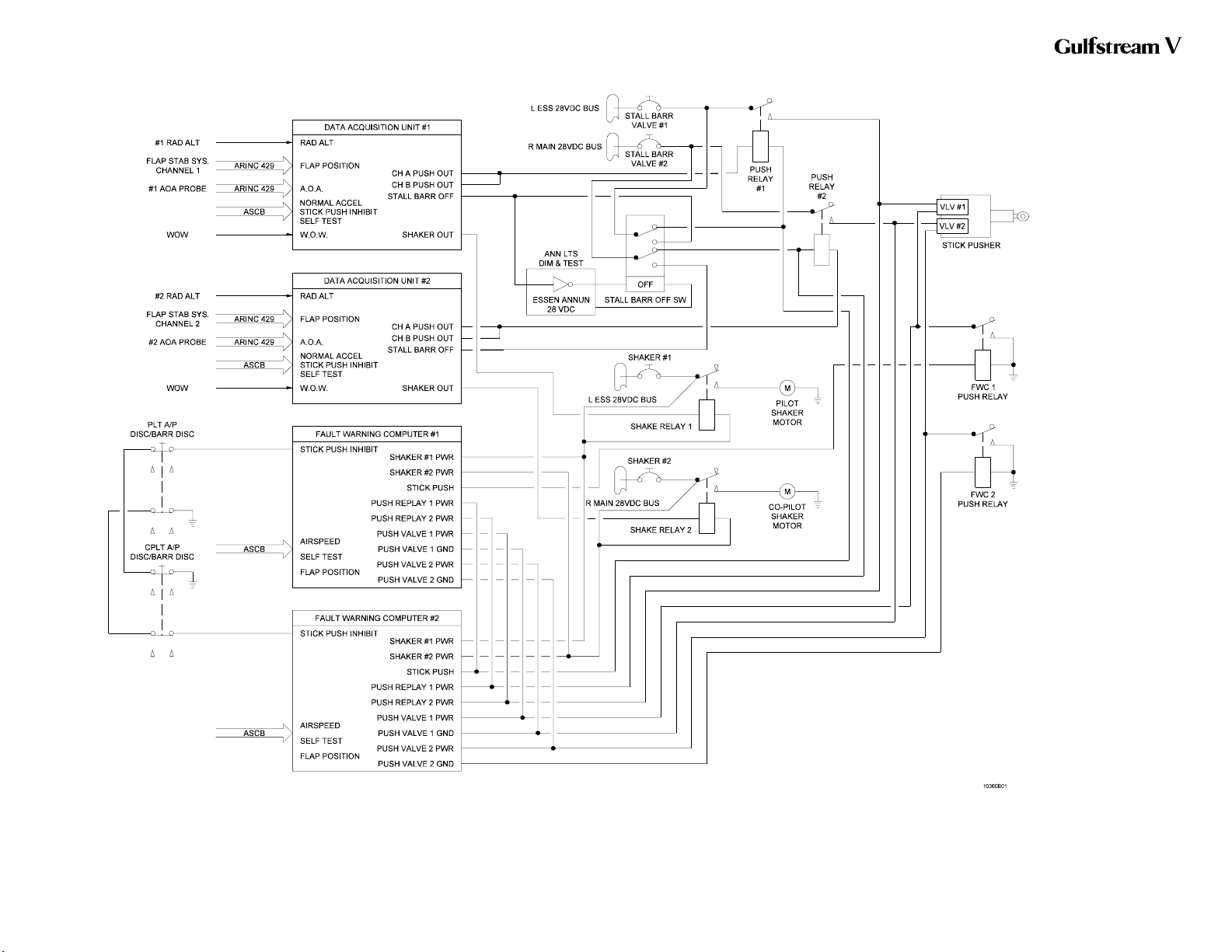
Two stall barrier systems are incorporated into the elevator control system to
prevent a stall by forcing the control columns forward when the crew fails to
respond either to visual indications or to stick shaker vibrations which precede an
impending stall. The stall barrier system is normally left on, but if it is
malfunctioning, the crew can turn the system off, using the STALL BARR switch,
located on the cockpit center pedestal. When a high angle of attack is attained, a
shaker trip point detector activates the control column shaker motors. When a
more severe angle of attack is attained, a pusher trip detector activates its
respective stall barrier pusher.
NOTE:
The control column force can be manually overcome
by pilot or copilot.
2. Description of Subsystems, Units and Components:
A. Automatic Hardover Prevention System:
The elevator actuator incorporates a hardover prevention system which
compares inputs and outputs. If inputs to, and outputs from, the actuator do
not agree, hydraulic pressure to the affected side of the actuator is shut off
and a message is prompted for display on the Crew Alerting System (CAS)
display. The elevators are still operative, but without benefit of the affected
side’s hydraulic boost. The hardover prevention system receives power
from the Left and Right Essential DC bus.
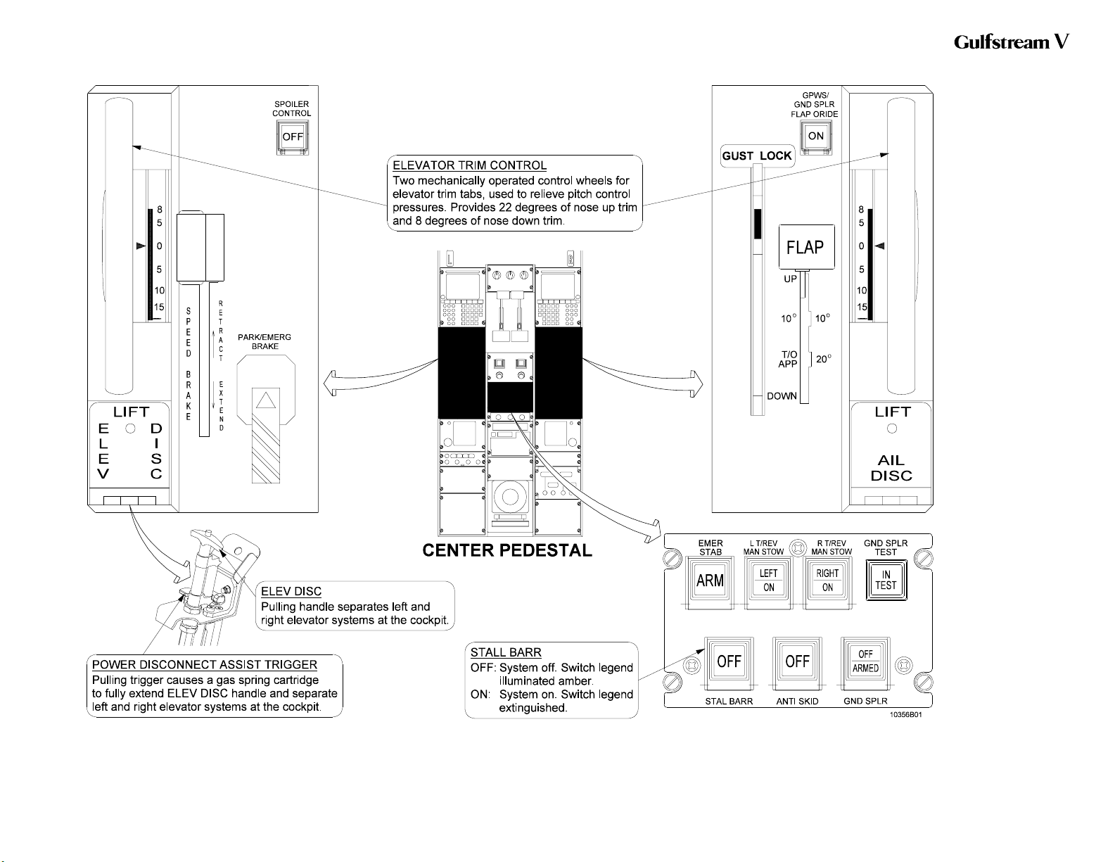
B. Elevator Control Separation System:
(See Figure 4.)
The elevator control systems are dual and separable. In the unlikely event
that a single elevator control system were to become jammed, an elevator
disconnect system provides the means to separate the left and right
elevators from each other. This is accomplished through the use of an
elevator disconnect system, located on the left side of the cockpit center
pedestal and labeled ELEV DISC on its protective cover.
The elevator disconnect system consists of the protective cover, the
elevator disconnect handle (labeled ELEV DISC) and a power assist trigger
(labeled LIFT). If a jammed elevator is detected, the protective cover is
raised and the ELEV DISC handle is pulled. With the handle fully extended,
the pilot’s and copilot’s control columns are separated in the cockpit. The
pilot controls the left elevator and the copilot controls the right elevator. The
immovable elevator side will remain immovable and the movable side is
now free to be used to control the aircraft. The Stall Barrier system remains
functional in this configuration.
If the red power assist trigger was NOT used to actuate the ELEV DISC
handle, the elevator disconnect system can be reset at the discretion of the
flight crew.
If the force required to pull the ELEV DISC handle is too great, the red
power assist trigger, located under the ELEV DISC handle, is pulled. This
OPERATING MANUAL
PRODUCTION AIRCRAFT SYSTEMS2A-27-00
Page 6
May 22/01
Title Page
Prev Page
Next Page
TOC
actuates a gas-spring cartridge, providing between 110 to 150 pounds of
controlled force to fully extend the handle and separate the elevator control
systems.
NOTE:
If the red power assist trigger was used to actuate the
ELEV DISC handle, the system cannot be reset
without the use of special tools.
C. Pitch Trim System:
(See Figure 4 through Figure 6.)
(1) Elevator Trim Tabs:
A trim tab is installed on the trailing edge of each elevator. They are
mechanically operated through trim actuators located in each
elevator. The trim actuators can be operated manually or electrically
as described below. Elevator trim tab travel ranges from 22 degrees
trailing edge down to 8 degrees trailing edge up.
(2) Elevator Trim Tab Actuator Heater:
The elevator trim tab actuator heater generates heat to prevent the
actuators from freezing. These heaters generate heat until the
temperature rises to a threshold temperature, predetermined by the
manufacturer. The heaters are controlled by the L/R ELEV TRIM
HEAT circuit breakers, located on the Right Electronic Equipment
Rack (REER), and receives power from the Right Main AC bus.
(3) Manual Trim Control:
Manual control of pitch trim is accomplished by an interconnected
manual trim control wheel set. A control wheel is provided on each
side of the cockpit center pedestal. With electric pitch trim
disengaged, moving either manual trim control wheel adjusts pitch
trim to the desired setting. With electric pitch trim engaged, the
manual trim control wheels move automatically corresponding to the
amount of electric pitch trim movement.
(4) Electric Pitch Trim:
Located on the pilot’s flight panel, the PITCH TRIM ENG/DISENG
switch engages or disengages the electric pitch trim. Pitch trim is
automatically engaged when the autopilot is engaged. However,
pitch trim is not automatically disengaged when the autopilot is
disengaged. To disengage the pitch trim, the ENG/DISENG switch
must be depressed, causing the DISENG legend to illuminate in the
switch. Pitch trim can be engaged even if the autopilot is off by
depressing the ENG/DISENG switch. Should a failure occur
rendering the electric pitch trim inoperative, or pitch trim become
disengaged, messages are prompted for display on CAS. The type
of messages depend upon aircraft airspeed.
With electric pitch trim engaged, pitch trim can be adjusted through
use of a split-half pitch trim switch installed on each control wheel,
labeled NOSE DOWN / NOSE UP. Inadvertent actuation of pitch
trim, including runaway, is minimized through the split-half switch
design. In order for the pitch trim to be actuated, both halves of the
OPERATING MANUAL
PRODUCTION AIRCRAFT SYSTEMS 2A-27-00
Page 7
May 22/01
Title Page
Prev Page
Next Page
TOC
switch must be simultaneously moved in the same direction. When
electric pitch trim reaches the nose up or nose down limit of
allowable travel, messages are prompted for display on CAS. The
type of messages depend upon whether or not the autopilot is
engaged.
D. Stall Barrier System:
(See Figure 3, Figure 4 and Figure 6.)
The stall barrier system consists of stick shaker motors located on each
control column, a stick pusher actuator located in the tail compartment and
Angle of Attack (AOA) probes located on each side of the fuselage forward
section.
The stall barrier system can be deactivated by depressing the autopilot
disconnect switches (A/P DISC / BARR DISC) on either control wheel, or
by selecting the STALL BARR switch, located on the center console, to the
OFF position. When the stall barrier system is selected off, a message is
prompted for display on CAS.
NOTE:
The autopilot servo input to the elevator control
system is through a separate set of cables connected
to the elevator actuator. Servo inputs are introduced at
the actuator. The force generated by the stall barrier
system will overcome autopilot force.
(1) Stick Shaker Motor:
Two stick shaker motors are connected to the pilot and copilot
control columns. Upon activation, the motor provides a warning by
shaking the control column. The pilot’s stick shaker motor is
connected to the Left Essential DC bus through the SHAKER #1
circuit breaker and a relay activated by Data Acquisition Unit (DAU)
#1. The copilot’s stick shaker motor is connected to the Right Main
DC bus through SHAKER #2 circuit breaker and a relay activated by
DAU #2. If a failure is detected in either stick shaker, a message is
prompted for display on CAS.
(2) Stick Pusher Actuator:
The stick pusher actuator is controlled through two independent
electro-hydraulic valves. The left valve is controlled by either
channel of DAU #1 and Fault Warning Computer (FWC) #1, and the
right valve is controlled by either channel of the DAU #2 and FWC
#2, in order to eliminate single point failures. The #1 stick pusher
valve is connected to the Left Essential DC bus through the STALL
BARR VALVE #1 circuit breaker and the PUSH #1 relay. The #2
stick pusher valve is connected to the Right Main DC bus through
the STALL BARR VALVE #2 circuit breaker and the PUSH #2 relay.
The actuator is normally loaded in the retracted position. When the
stick pusher is activated, a message is prompted for display on
CAS, the solenoids are energized and the actuator extends.
Extension of the actuator provides mechanical force to push the
control column forward.
OPERATING MANUAL
PRODUCTION AIRCRAFT SYSTEMS2A-27-00
Page 8
May 22/01
Title Page
Prev Page
Next Page
TOC
The stall barrier system is constantly monitored for faults or failures.
If a fault or failure in the control column pusher is detected,
messages are prompted for display on CAS.
(3) Angle of Attack Probe:
Two heated Angle of Attack (AOA) probes provide aircraft AOA
information via the Aeronautical Radio Incorporated (ARINC) 429
databus to the DAUs. The left AOA probe provides information to
DAU #1 and the right AOA probe provides information to DAU #2.
AOA values are displayed on the Primary Flight Display (PFD).
The AOA system is constantly monitored for faults or failures. If a
probe heater failure occurs, or data transmitted by the probes to
their respective DAUs is in gross disagreement, messages are
prompted for display on CAS.
3. Controls and Indications:
(See Figure 3 through Figure 6.)
NOTE:
A full description of the Primary Flight Display can be
found in section 2B-02-00: Electronic Display System
Description. A full description of the FLIGHT
CONTROLS synoptic page can be found in section
2B-03-00: Engine Instruments and Crew Alerting
System Description.
A. Circuit Breakers (CBs):
The pitch flight controls system is protected by the following CBs:
Circuit Breaker Name: CB Panel: Location: Power Source:
L ELEV TRIM HEAT REER E-16 R MAIN AC Bus
R ELEV TRIM HEAT REER F-16 R MAIN AC Bus
LEFT ELEV HYD S/O POP C-5 L ESS DC Bus
RIGHT ELEV HYD S/O CPOP C-5 R ESS DC Bus
STALL BARR VALVE #1 POP E-5 L ESS DC Bus
STALL BARR VALVE #2 CPOP E-5 R ESS DC Bus
SHAKER #1 POP E-6 L ESS DC Bus
SHAKER #2 CPOP E-6 R MAIN DC Bus
AOA PROBE #1 POWER LEER F-4 L ESS DC Bus
AOA PROBE #2 POWER REER F-13 R ESS DC Bus
B. Crew Alerting System (CAS) Messages:
CAS messages associated with the pitch flight controls system are as
follows:
Area Monitored: CAS Message: Message Color:
Stall Warning System AOA MISCOMPARE Amber
AOA Probe(s) AOA PROBE 1/2 FAIL Amber
Integrated Avionics Computer(s) EL MISTRIM NOSE DN Amber
Integrated Avionics Computer(s) EL MISTRIM NOSE UP Amber
OPERATING MANUAL
PRODUCTION AIRCRAFT SYSTEMS 2A-27-00
Page 9
May 22/01
Title Page
Prev Page
Next Page
TOC
Area Monitored: CAS Message: Message Color:
L/R Elevator Deactivation
Valve(s) L/R ELEV HYD OFF Amber
Electric Pitch Trim ELEV TRIM INOP Amber
Integrated Avionics Computer(s) MACH TRIM INOP Amber
Stall Warning System STALL BARRIER 1/2 Amber
STALL BARR Switch STALL BARRIER OFF Amber
Stall Warning System STCK PSH 1/2 FAULT Amber
Stall Warning System STICK PUSH UNAVAIL Amber
Stall Warning System STICK PUSH 1/2 FL Amber
Electric Pitch Trim EL TRIM DN LIMIT Blue
Electric Pitch Trim EL TRIM UP LIMIT Blue
Stall Warning System STICK SHAKE 1/2 FL Blue
4. Limitations:
A. Stall Barrier / Stall Warning:
(1) Takeoff Requirements:
Both stall warning / stall barrier systems must be operative for
takeoff.
(2) Use of System:
Operative stall barrier systems must be ON during all flight
operations, unless required to be selected OFF for procedural
reasons. Refer to Section 05-13-50: Stall Barrier Malfunction, for
additional information.
B. Mach Trim / Electric Elevator Trim Inoperative Speed:
With both mach trim compensators inoperative, or electric elevator trim
inoperative, the maximum operating limit speed is 0.80 MT.
OPERATING MANUAL
PRODUCTION AIRCRAFT SYSTEMS2A-27-00
Page 10
May 22/01
Title Page
Prev Page
Next Page
TOC
Stall Barrier System Block
Diagram
Figure 3
OPERATING MANUAL
2A-27-00
Page 11 / 12
May 22/01
Title Page
Prev Page
Next Page
TOC
Pitch Flight Controls
System Controls and
Indications (Cockpit
Center Pedestal)
Figure 4
OPERATING MANUAL
2A-27-00
Page 13 / 14
May 22/01
Title Page
Prev Page
Next Page
TOC