Gunson Gastester G4125 User manual

Handbook
Digital Exhaust CO Analyser with Pulse Pump
GASTESTER
GASTESTER
Part No. G4125

Index
1. Kit Contents.......................................... 4
2. Assembly .............................................. 4
3. Descriptions and controls................... 5
4. Preparations before use ...................... 6
5. Instructions for use.............................. 7
6. Further information.............................. 8
7. Common problems............................... 9
8. Warranty................................................ 11
32
Gastester is an exhaust gas analyser that works on the “hot wire” or “thermal conductivity”
principle: the thermal conductivity of exhaust gas varies in proportion to the amount of carbon
monoxide present. Exhaust gas is pumped through the Gastester by an externally mounted
pulse pump.
The pulse pump uses the positive and negative pressure waves generated by the exhaust gas to
force exhaust gas through the Gastester.
The pump consists of a diaphragm with one way valve and thus the pump will only be heard to
click when connected to the exhaust.
CO Function Specification:
Calibrated range: 0-10% CO
(indicates un-calibrated to 20% C)
Accuracy: +/- 0.5% CO typical
(throughout the indicated range 0.5% CO to 6.5% CO)
Note: The Gastester measures the CO level only of the exhaust gas and is therefore not
suitable for MOT or diagnostic checks where an accuracy greater than +- 0.5% CO is
required.

DISPLAY:
This is calibrated in volume percent carbon monoxide (CO%).
CALIBRATION CONTROL:
This is used to set the reading of the display to show 2.0% at the start of the tests, before the
probe is inserted into the exhaust pipe.
Note: The calibrate position represents what the instrument should register when the
probe is in fresh air. It is coincidental that air should measure the same as exhaust gas
with 2% CO. When the probe is subsequently inserted into the exhaust pipe, the display of
the instrument may increase or fall from the calibrate condition.
TWO CORE CABLE WITH CLIPS:
(for connecting to the car battery)
EXHAUST PROBE:
The aluminium pipe is for insertion into the exhaust pipe and is held in position by the metal
springs which press against the inside of the exhaust pipe.
NB: In use the pipe from the exhaust probe should slope down continuously to the pulse pump/
water trap so that water runs down and may be automatically expelled from the drain pipe.
1. Kit Contents
1. Gastester instrument including collector box and pulse pump/water trap assembly
2. Metal exhaust probe with retaining springs
3. Flexible plastic pipes (3 lengths)
4. Instruction handbook
2. Assembly
• In cold conditions, warming the various plastic pipes will assist assembly.
• Press the shortest pipe onto the lower port of the pulse pump/water trap as shown in the
diagrams Figures 1 and 2. This is the automatic water drain.
• The longest plastic pipe is connected to the pulse pump inlet (centre port) and the other end
to the aluminium exhaust probe tube.
• Connect the remaining plastic pipe between the pulse pump (top) outlet and the collector box
inlet. (This connection is intentionally vented at the inlet boss). The connection to the collector
box inlet needs to be pressed fully home.
Figure 2
4
Figure 1
1. Kit Contents
2. Assembly
5
3. Descriptions
and Controls

• Any service and maintenance such as air filter renewal, tappet adjustment, carburettor
maintenance, ignition maintenance including ignition timing, should be carried out before
setting the carburettor or fuel injection mixture adjustment. Petrol mixture setting should be
the final adjustment in any engine tuning work.
• Carbon monoxide is an extremely poisonous gas and any work on the car with the engine
running should therefore be carried out in the open air. Take care not to breathe in gases
when using the gas tester.
• Study the workshop manual for the particular vehicle or engine to identify the correct
adjustment screws that control the mixture strength and the idle speed. Make a note of the
initial position of the adjustments before commencing work.
• The car should be fully up to running temperature before connecting the Gastester. In order
to achieve full temperature the vehicle should be driven till oil, water and the exhaust system
are all fully up to temperature.
• Have to hand the correct tools for making the necessary adjustments. If the manual
recommends a CO level at a particular engine speed, then a tachometer should be used.
2 26 7
Note: Place the main body of the instrument away from the exhaust gas stream. Clean air
is required in the internal reference cell for accurate readings.
1. Place the Gastester on a convenient flat stationary surface close to the vehicle’s exhaust pipe
outlet. Switch off the engine temporarily while making connections. Connect the red (+) and
black (-) clips to the vehicle’s 12 V battery or convenient positive and earth (ground) points.
(Do not use this Gastester with 6v or 24v batteries.)
2. Fit the probe to the Gastester but do not fit to the exhaust at this stage.
3. Allow a minimum period of eight minutes with the instrument probe in fresh air. Set the
calibration control to achieve 2.0% on the CO range and observe the display for a further two
minutes minimum to ensure that the reading has stabilized.
Note: if it has not stabilised allow a further two minutes before attempting to measure
exhaust CO level.
4. During the warm up period check and adjust the engine idle RPM if required.
5. Check the calibrated reading is still set at 2.0% in fresh air, once set and stable do not mover
the Gastester.
6. Insert the probe into the exhaust pipe a minimum 8” (20cm), the display will now show the
percentage level of CO in the exhaust. If the display remains at 2.0% then the percentage
level is 2% and happens to match the percentage level found in fresh air
Note: In order for the automatic water drain to function, the probe pipe should fall
continuously from the exhaust end to the inlet end to allow water droplets to run down.
Otherwise the water will collect at the lowest point and will have to be drained manually.
7. After insertion of the pipe wait for a period of 15 seconds for the meter to respond and a
further 1 minute to stabilise (the reading may overshoot before returning to a steady value,
particularly during the initial measurement).
8. Make a note of the reading and observe the display for a further one or two minute to confirm
that the reading is steady and within tolerance for the vehicle concerned. If the reading is
outside the manufacturer’s recommended limits, or is not below that specified as a legal
requirement, then adjustment of the carburettor or fuel injection system will be required.
9. If adjustment is required, make a small alteration to the mixture screw, and correct the idle
speed after each adjustment. After each adjustment wait for at least one minute for the
reading to stabilise.
10.When the test is complete remove the exhaust probe and switch off the engine. Leave the
Gastester connected to the vehicle’s battery and allow a period of at least 10 minutes for fresh
air to purge the exhaust from the instrument. This period in fresh air with the power on cleans
the sensor before storage and also allows a check to ensure the display returns close to the
2% setting indicating that there has been little drift in calibration.
Note: A final reading of 1.8% in air for example would suggest that the last exhaust
measurement was approx 0.2% lower than the displayed level. While this is perfectly
acceptable when setting to approx 3% it does represent a more significant error if setting
to a manufacturer’s recommended 0.5% CO. On occasions it may be necessary to repeat a
test if calibration drift is excessive (drift is reduced by keeping test duration short
and allowing a longer warm up).
4. Preparations
before use
5. Instructions for use

General Notes
• During testing, check the exhaust sample pipe (from the probe) for any signs of water build
up that will reduce the flow of exhaust gas. Remove any build up of water as soon as it is
seen. If the transparent pipe falls continuously from the exhaust to the pump the automatic
drain should operate and keep the pipe clear of water. Operation of the pulse pump will
usually be audible as the pulsations in the exhaust cause the internal diaphragm to vibrate. If
the instrument ceases to respond to changes in mixture setting or the sound from the pulse
pump becomes irregular, check the sample pipe for collected water.
• It should be noted that engines not fitted with catalytic convertors, even in good overall
condition, will show a fluctuation in idle CO over a period of time, of typically 0.5%. Bearing
in mind this fluctuation, and also errors and drift in the instrument, the user should aim to set
the average CO reading to be midway between the limits set by the manufacturer, or at a
reasonable margin below the prescribed legal limit.
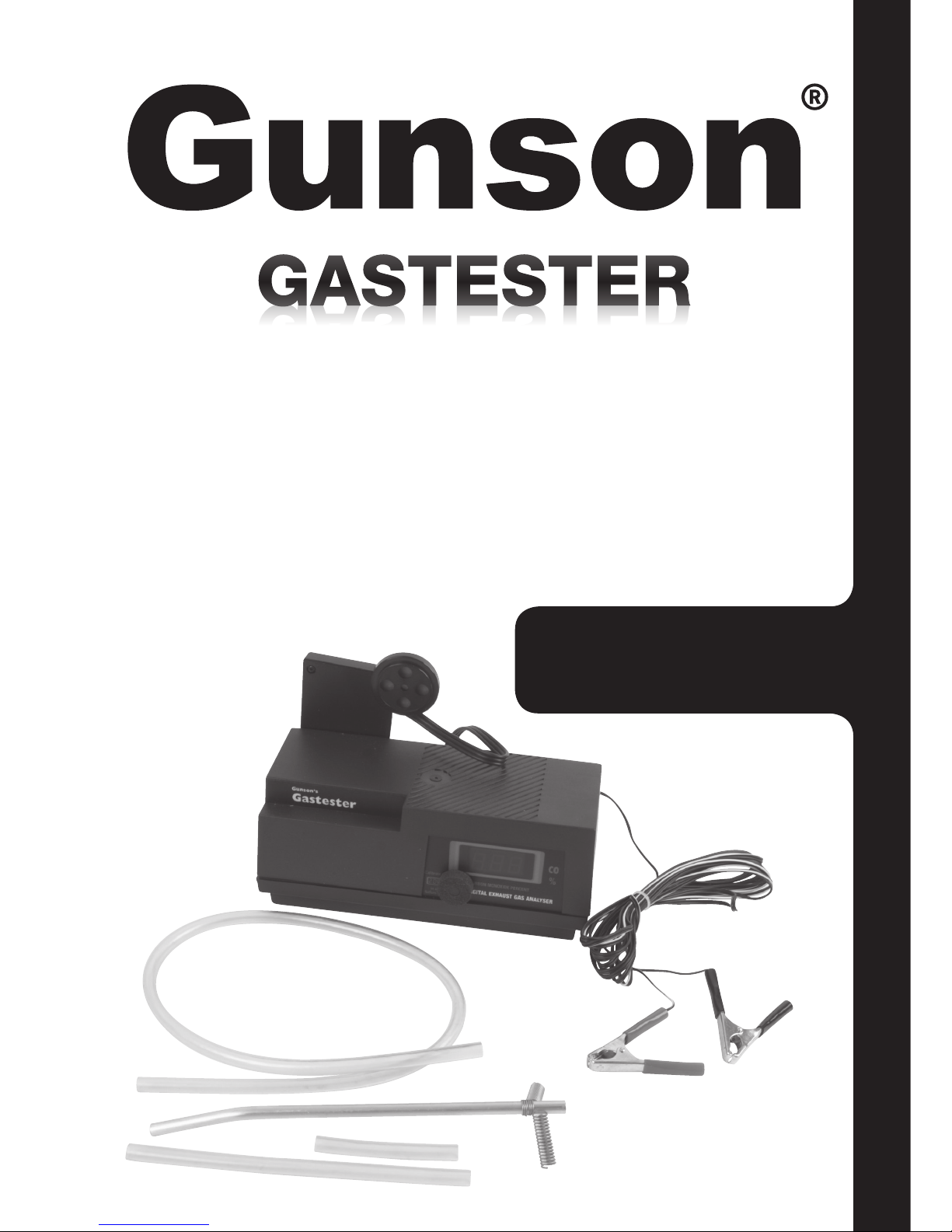
• Calibration of the instrument may be checked at any time. Simply remove the exhaust probe
and wait at least ten minutes in fresh air, for the exhaust gas to disperse from the collector
box. If necessary, the calibration may then be adjusted using the calibration control knob.
• It is advised to periodically check the calibration of the instrument during particularly
extended tests.
• Some older engines will not readily tick over at idle speeds for long periods. The speed may
become erratic, and engine misfiring may occur. With the prolonged testing of such engines,
it may be necessary to occasionally purge the engine by, for instance, increasing the speed
to 2000 rpm - 3000 rpm for 15 seconds. This may be done at any time during the tests but
the exhaust probe should be removed beforehand.
• For engines fitted with a catalytic convertor if the catalyst is in good working order and fully
up to temperature the reading should be less then 0.5% if it is higher than this then either
the catalyst is not up to temperature, internally fouled, has failed or the engine is running
excessively rich.
• If the exhaust pipe has a curved inlet it may be necessary to slightly bend the metal exhaust
probe to give better fit. Avoid kinking the pipe and restricting the flow. Full insertion of the
exhaust probe is essential for accurate readings.
• Use only a 12 volt car battery in good condition as power supply. A faulty or flat car battery
may not be able to supply adequate current to the instrument (Gastester draws about 0.8
amps), resulting in errors in use and difficulty in calibration.
Q. The car does not drive well with the correct idle mixture setting.
A. This is a common complaint. On older vehicles the cause is likely to be a fuel system fault
which creates a weak mixture just above idle speed. Clean the idle jet and idle air bleed jet
on fixed choke carburettors. Check for needle/jet wear on variable choke carburettors (above
40,000 miles). These are available as spare parts. Check acceleration enrichment device.
Q. The correct mixture setting cannot be achieved/setting is continually too rich.
A. Clean the idle air bleed jet and air passage on fixed choke carburettors. Check for severe
needle jet wear on variable choke carburettors. Check for high fuel level in the float chamber.
Check cold start device.
Q. Setting is continually too weak.
A. Clean the idle jet on fixed choke carburettors. Check needle and jet for disengagement from
adjusting device or sticking on variable choke carburettors. Check for air leaks.
Q. The engine misfires or is unstable at idle with the correct mixture setting.
A. Misfire/engine instability causes increase in HC reading and potential emission test failure
even with correct CO level. Check for general engine condition – compression pressures,
sparking plugs etc. Check for air leaks, these may cause severe variation in mixture between
cylinders. Investigate mixture quality i.e. fuel air mixture may not be finely atomized due to
partially blocked air jets or prematurely feeding main jet system caused by high float chamber
level etc. Check for advanced ignition timing, tight valve clearances, slow idle speed
Q. The mixture setting drifts
A. Check for leaking float chamber needle valve if CO level steadily increases with prolonged
idle. Check for high float chamber level. Check Gastester CALIBRATION in air, slight drift
will occur during extended operation. Good stability should be obtained over a period of five
minutes or more. A variation of, for example 0.5% CO at ¬ CO is not uncommon on an engine
which is in good working order.
Q. Gastester gives errors or slow/no response to mixture changes.
A. Check for water in the probe pipe and adequate probe insertion; minimum 8 inches/20 cm. If
a baffled silencer with no tailpipe is fitted, as on some motorcycles, temporary restriction of
the exhaust outlet or temporary fitting of a tailpipe extension may be the only way to achieve
acceptable results.
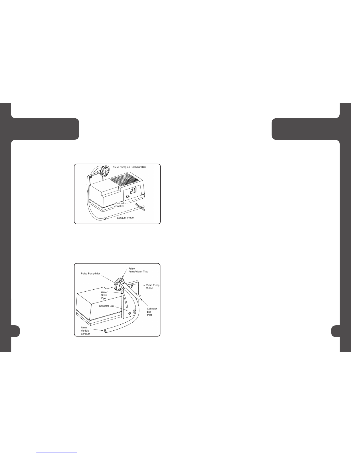
Note: In use the pipe from the exhaust probe should preferably slope down continuously
to the Pulse Pump/Water Trap so that water runs down and may be automatically
expelled from the drain pipe. Operation of the pulse pump is clearly audible as the internal
diaphragm vibrates with pulsations from the exhaust, if response is obtained at higher
than idle speeds only, Pulse Pump may need replacement. (Alternatively twist the pump
cap on the body to re-seat the diaphragm). If the pump is working, the vehicle mixture
adjustment may be ineffective.
Q. Gastester Professional cannot be set to the Calibration Condition in air after warm-up.
A. First check that the unit is switched correctly to CO range and is used in a horizontal position
(the unit will not operate correctly if instrument is significantly inclined or if the instrument
angle is changed after calibration). Ensure that the unit is connected to a car battery
(NB: a 12v dry cell battery or a faulty car battery can not provide enough current and are
unsatisfactory). Ensure that the unit is correctly warmed up (allow at least 10 minutes).
8 9
6. Further Information 7. Common Problems

Ensure that the unit is being calibrated to the 2% CO condition, NOT at zero). Ensure that the
probe is in air, not in the exhaust pipe. If these checks do not resolve the problem, it is possible
that the instrument has “drifted” generally due to collector box contamination or damage due to
impact (the instrument is more susceptible to damage when warm and in use); the unit should be
returned to The Tool Connection for service.
Higher Engine Speeds:
• The Gastester is designed to work at engine tick-over speeds; however it will also give a
reliable reading at higher engine speeds. Violent full throttle action to high engine speeds
should be avoided while the probe is inserted in the exhaust pipe; the pulse pump diaphragm
can be damaged in extreme circumstances.
• To test mixture weakening at higher RPM, increase the engine speed in increments of
approximately 300 RPM to 400 RPM up to a maximum of 2500 RPM, observing the reading
between each adjustment. (Remember that the instrument may take 15 seconds to respond
to a particular adjustment.) The CO level should fall progressively and stay low during a
gradual increase in speed.
• The mixture enrichment for acceleration can be tested by rapid opening and immediate
release of the accelerator. Opening to half throttle should be sufficient. Within a few seconds
of this operation the Gastester CO indication should increase before returning to its previous
setting. The degree of increase will vary according to how this procedure is carried out and
also with the type of fuel system. A fixed choke carburettor with accelerator pump will usually
give a more pronounced increase than a variable choke carburettor or fuel injection system.
More information on Gunson web site:
Over the years hundreds of different types of carburettor have been designed and used and thus
it is not possible to give a definitive guide to carburettor adjustment. For this reason Gunson
strongly advise the use of vehicle manufacturer data and service instructions.
Gunson have put together general guidance notes on carburettor adjustments, including fixed
and variable jet carburettors, multiple carburettors and fuel injection available only for download
from: www.gunson.co.uk
This warranty is in addition to the statutory rights of the purchaser.
The Tool Connection has made every effort to ensure that this product is of the highest quality
and value to the customer. However, The Tool Connection can accept no responsibility for
consequential damage howsoever caused arising from the use of this product.
All technical enquiries regarding this product should be made to:
The Tool Connection Technical Service Department: +44 (0) 1926 818181
Please note that The Tool Connection cannot provide technical information or advice or service
data on particular motor vehicles.
If this product should require service or repair, it should be returned to:
The Tool Connection
Kineton Road
Southam
Warwickshire
CV47 0DR
England
Please give full details of faults requiring attention when sending goods for service or
repair.
12 1310 11
8. Warranty

Other manuals for Gastester G4125
2
Table of contents
Other Gunson Measuring Instrument manuals
Popular Measuring Instrument manuals by other brands

PCB Piezotronics
PCB Piezotronics J352B/ACS-23 Installation and operating manual

LaserLiner
LaserLiner PrecisionCross-Laser PCL 5P RXR operating instructions

MBA Instruments
MBA Instruments MLA 900 operating instructions

DEHAS
DEHAS QualityMix N2O Series user manual

Skil
Skil 2100DAF Operating/safety instructions

Tegam
Tegam 1806 instruction manual