gunt ET 796 User manual

Instruction Manual
ET 796 Gas Turbine as Jet
Engine


i
DTP_3
11/2007
All Rights Reserved G.U.N.T. Gerätebau GmbH, Barsbüttel, Germany 11/2005
Instruction Manual
Please read and follow the safety regulations before the first installation!
Publication-no.: 916.000 00 B 796 03 (A) DTP_3
ET 796
GAS TURBINE AS JET ENGINE

Table of Contents
1 Introduction . . . . . . . . . . . . . . . . . . . . . . . . . . . . . . . . . . . . . . . 1
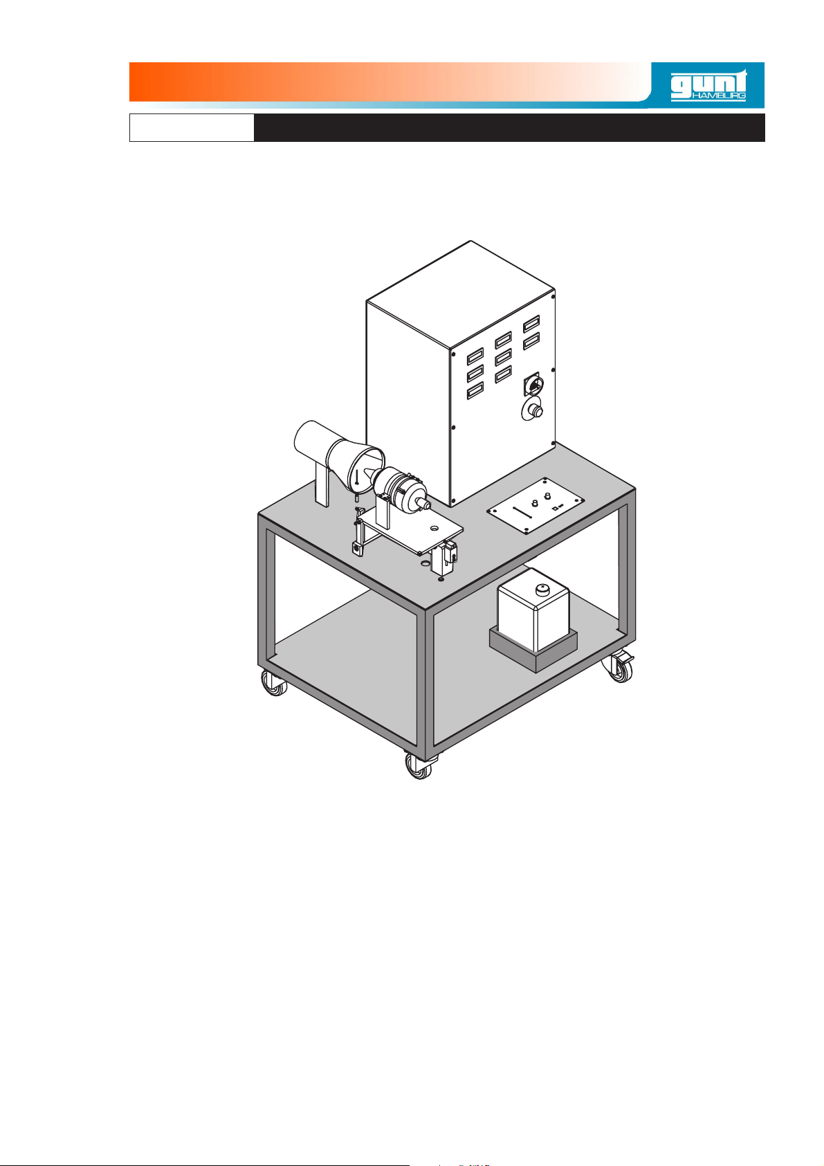
2 System description . . . . . . . . . . . . . . . . . . . . . . . . . . . . . . . . . . 3
2.1 Function. . . . . . . . . . . . . . . . . . . . . . . . . . . . . . . . . . . . . . . . . . . . . . . 5
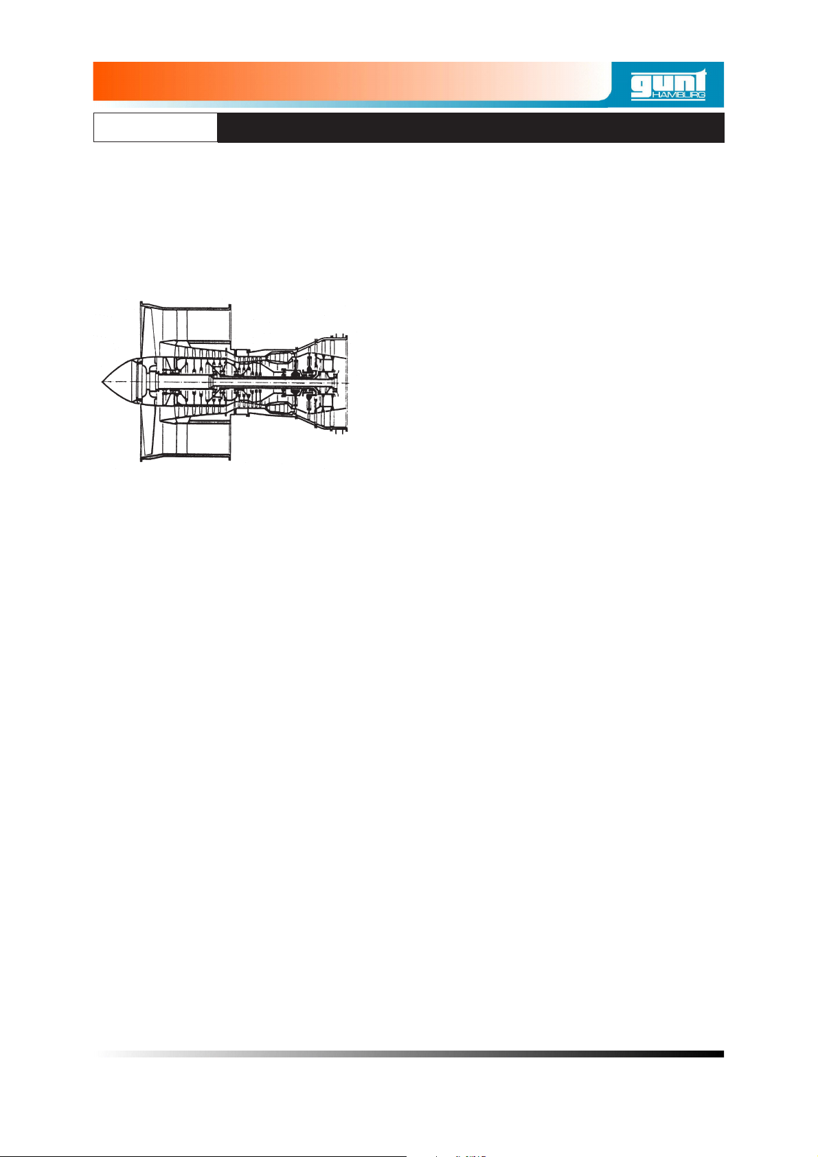
2.1.1 Jet turbine. . . . . . . . . . . . . . . . . . . . . . . . . . . . . . . . . . . . . . . 5
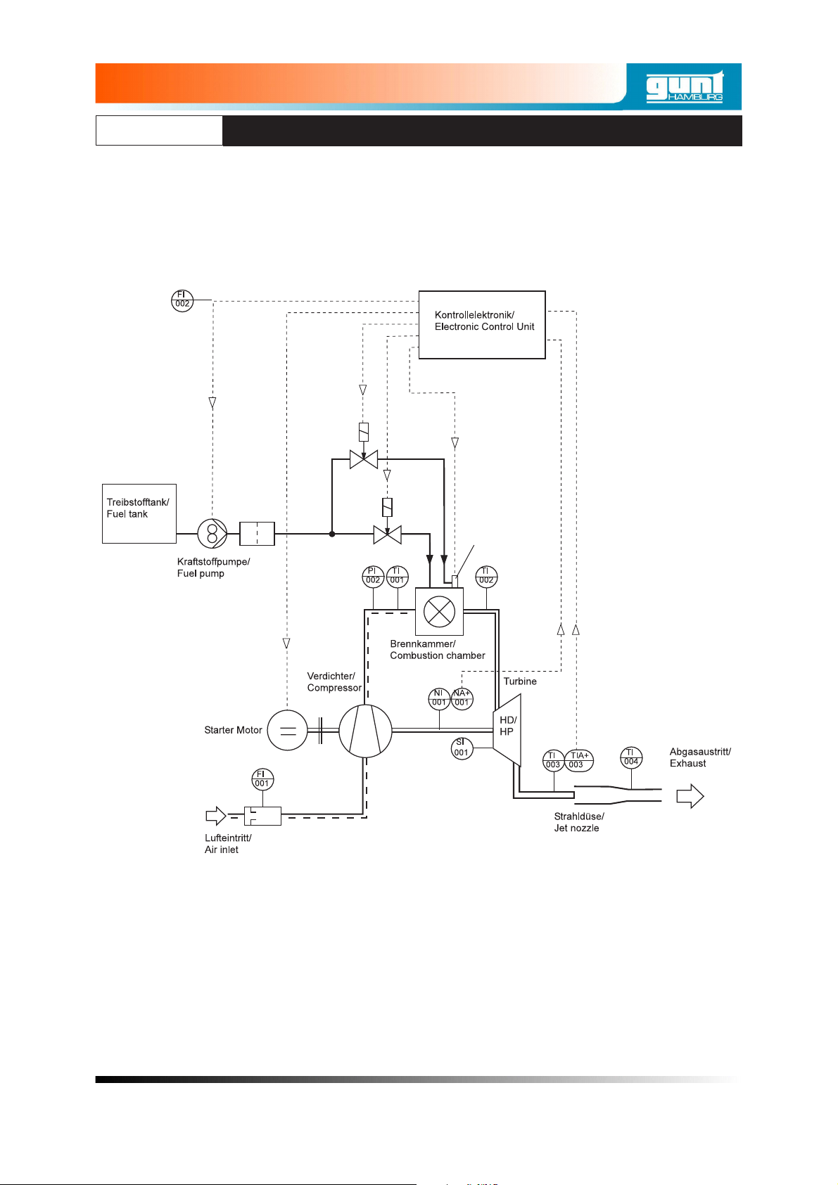
2.1.2 Fuel system . . . . . . . . . . . . . . . . . . . . . . . . . . . . . . . . . . . . . 8
2.1.3 Starter and ignition system . . . . . . . . . . . . . . . . . . . . . . . . . . 8
2.2 Controls. . . . . . . . . . . . . . . . . . . . . . . . . . . . . . . . . . . . . . . . . . . . . . . 9
2.3 Layout of the experimental module . . . . . . . . . . . . . . . . . . . . . . . . . 11
2.4 Setting up and maintaining the gas turbine . . . . . . . . . . . . . . . . . . . 12
2.4.1 Checking the gas turbine . . . . . . . . . . . . . . . . . . . . . . . . . . 12
2.4.2 Setting up . . . . . . . . . . . . . . . . . . . . . . . . . . . . . . . . . . . . . . 13
2.5 Operation of the gas turbine . . . . . . . . . . . . . . . . . . . . . . . . . . . . . . 15
2.5.1 Preparations for starting . . . . . . . . . . . . . . . . . . . . . . . . . . . 15
2.5.2 Starting up the gas turbine . . . . . . . . . . . . . . . . . . . . . . . . . 17
2.5.3 Operation of the gas turbine . . . . . . . . . . . . . . . . . . . . . . . . 19
2.5.4 Shutting down the gas turbine . . . . . . . . . . . . . . . . . . . . . . 20
2.6 Maintenance . . . . . . . . . . . . . . . . . . . . . . . . . . . . . . . . . . . . . . . . . . 21
2.6.1 Glow plug . . . . . . . . . . . . . . . . . . . . . . . . . . . . . . . . . . . . . . 21
2.6.2 Inspecting the turbine . . . . . . . . . . . . . . . . . . . . . . . . . . . . . 21
2.7 Faults and fault rectification. . . . . . . . . . . . . . . . . . . . . . . . . . . . . . . 22
2.8 Software . . . . . . . . . . . . . . . . . . . . . . . . . . . . . . . . . . . . . . . . . . . . . 24
3 Safety instructions. . . . . . . . . . . . . . . . . . . . . . . . . . . . . . . . . . 31
3.1 Hazards for life and limb . . . . . . . . . . . . . . . . . . . . . . . . . . . . . . . . . 32
3.2 Special safety rules for handling kerosene . . . . . . . . . . . . . . . . . . . 33
3.3 Hazards for unit and function. . . . . . . . . . . . . . . . . . . . . . . . . . . . . . 34
ii
ET 796
GAS TURBINE AS JET ENGINE
11/2007

4 The open gas turbine process. . . . . . . . . . . . . . . . . . . . . . . . . 37
4.1 Representation in heat diagram . . . . . . . . . . . . . . . . . . . . . . . . . . . 38
4.1.1 Thermal efficiency (ideal) . . . . . . . . . . . . . . . . . . . . . . . . . . 39
4.1.2 Specific work capacity . . . . . . . . . . . . . . . . . . . . . . . . . . . . 40
4.1.3 Representation in p/v diagram . . . . . . . . . . . . . . . . . . . . . . 41
4.2 Gas turbine as jet engine. . . . . . . . . . . . . . . . . . . . . . . . . . . . . . . . . 42
5 Experiments . . . . . . . . . . . . . . . . . . . . . . . . . . . . . . . . . . . . . . 43
5.1 Recording of measurements . . . . . . . . . . . . . . . . . . . . . . . . . . . . . . 43
5.2 Air mass flow and fuel mass flow . . . . . . . . . . . . . . . . . . . . . . . . . . 44
5.3 Further characteristic quantities of an aeroplane jet turbine . . . . . . 45
5.4 Evaluation of measurement results . . . . . . . . . . . . . . . . . . . . . . . . . 48
5.4.1 Representation of measured data in diagrams . . . . . . . . . . 48
5.4.2 Calculation of air ratio . . . . . . . . . . . . . . . . . . . . . . . . . . . . . 53
6 Appendix . . . . . . . . . . . . . . . . . . . . . . . . . . . . . . . . . . . . . . . . . 55
6.1 Working sheet for recording measured values . . . . . . . . . . . . . . . . 55
6.2 Technical data . . . . . . . . . . . . . . . . . . . . . . . . . . . . . . . . . . . . . . . . . 56
6.3 Symbols. . . . . . . . . . . . . . . . . . . . . . . . . . . . . . . . . . . . . . . . . . . . . . 59
6.4 Parts of delivery. . . . . . . . . . . . . . . . . . . . . . . . . . . . . . . . . . . . . . . . 59
6.5 Index . . . . . . . . . . . . . . . . . . . . . . . . . . . . . . . . . . . . . . . . . . . . . . . . 60
iii
ET 796
GAS TURBINE AS JET ENGINE
11/2007
All Rights Reserved G.U.N.T. Gerätebau GmbH, Barsbüttel, Germany 11/2005


1 Introduction
With the ET796 experimental module the function
and performance of a gas turbine can be demon-
strated and studied on model scale. Gas turbine
systems are used to generate mechanical and
electrical energy:
•Driving electricity generators in power
stations
•Driving compressors and pumps in oil and
gas production
•Driving ships, locomotives and heavy
vehicles
•For the propulsion of aircraft with propeller
and jet engines
Gas turbines are always used when high power
density, low weight and quick starting are required.
Contrary to piston engines, as fluid flow machines
they permit high material flow rates with small
dimensions. In this way lightweight, powerful
drives can be realised.
As the moving parts of a gas turbine only perform
rotary motion, almost vibration free running can be
achieved if the turbine is well balanced. Disad-
vantages are the high gas speeds and high noise
emissions due to the simultaneous connection to
the atmosphere.
In comparison to steam turbines, gas turbines
work at higher temperatures but with lower
pressures. The high temperatures particularly in
the area of the turbine require particularly heat
resistant materials.
1 Introduction 1
ET 796
GAS TURBINE AS JET ENGINE
11/2007
All Rights Reserved G.U.N.T. Gerätebau GmbH, Barsbüttel, Germany 11/2005
Fig. 1.1 Jet engine for the propulsion of
an aircraft

The experimental module includes a one-shaft
system. All components necessary for the
operation of the system are combined in a
compact arrangement on a trolley on castors.
The system is of straightforward construction and
is specially designed for training purposes. The
control and display of all important process
parameters is combined on a control panel.
Computerised data acquisition with evaluation
software permits online logging and graphical
representation of all relevant process variables.
As well as demonstrating how the system works,
the set-up can also be used to undertake
qualitative studies such as to determine the thrust,
and other characteristic data of the gas turbine.
2 1 Introduction
ET 796
GAS TURBINE AS JET ENGINE
11/2007

2 System description
The experimental module includes a complete gas
turbine system with the following subsystems:
–Model gas jet turbine comprising com-
pressor (1), turbine (2), combustion chamber
(3) and thrust nozzle with thrust gauge (4).
–Fuel system comprising tank (6), fuel pump
(7), quick-acting gate valve (8) and control
electronics (9).
–Starter and ignition system with starter
motor (10), auxiliary fuel valve (11) and glow
plug (12).
–Measuring instruments and controls with
temperature, flow rate, speed and pressure
measuring points and associated displays.
These also include the safety elements such
as temperature and speed governors.
A process schematic with all subsystems is given
on the next page.
2 System description 3
ET 796
GAS TURBINE AS JET ENGINE
11/2007
All Rights Reserved G.U.N.T. Gerätebau GmbH, Barsbüttel, Germany 11/2005

4 2 System description
ET 796
GAS TURBINE AS JET ENGINE
11/2007
Fig. 2.1 Prozessdiagram Gasturbine
6
78
9
10 12
3
4
11
12

2.1 Function
2.1.1 Jet turbine
The core of the plant is the model jet turbine
It consists of an axial turbine with a direct coupled
radial compressor and an annular combustion
chamber. The turbine and compressor, together
with the bearing housing in-between, form a
compact unit. This unit was originally used as the
propulsion unit for model aeroplanes.
The intake air is slung by the fast-rotating
compressor wheel (1) (35000 - 115000 rpm) into
the aluminium diffuser housing (2). Here the speed
of the air is converted into pressure. At the com-
bustion chamber (3) inlet part of the air is branched
off and fed to the front face of the flame tube (4).
The liquid fuel is passed from the rear into
so-called evaporator tubes (5). In them the fuel is
gasified, and in the front part of the combustion
chamber it is mixed with the primary air and
combusted. The flame tube is cooled from the out-
side by the secondary air. It is routed to the flame
2 System description 5
ET 796
GAS TURBINE AS JET ENGINE
11/2007
All Rights Reserved G.U.N.T. Gerätebau GmbH, Barsbüttel, Germany 11/2005
Fig. 2.2 Model jet turbine

tube by way of bores(6) in order to cool the very hot
combustion gases (approx. 2000°C) down to the
permissible turbine inlet temperature of 600 -
800°C. A glow plug (7) ignites the air/fuel mixture
during starting.
From the combustion chamber, the combustion
gases flow into the diffuser (8) of the turbine and
are accelerated before entering the axial wheel
(9). In the turbine, the gases discharge their
energy to the wheel to drive the compressor. In the
process, they are partially relaxed and cooled.
They are emitted into the thrust nozzle (10) at
approximately 600°C.
The turbine and compressor wheels are fitted to a
common shaft (11) such that they are over-
hanging. The shaft is guided on ball bearings(12)
in the bearing housing.
6 2 System description
ET 796
GAS TURBINE AS JET ENGINE
11/2007
Fig. 2.3 Model-jetturbine
15 14 1 2 3 7 4 5 6 8 9 10
13 12 11 12

The bearings are cooled by the compressor air and
The electronics (13) for the starter motor (15), tem-
perature monitoring and speed measurement (14)
are located under the front hood.
The exhaust gas jet draws additional secondary air
through the thrust tube by injection. This is mixed
with the exhaust gas jet in the thrust tube (17) and
reduces the inlet temperature for the power
turbine.
The entire turbine with the turbine desk (4) is sup-
ported on moving bearings, so that the thrust of the
turbine can be measured by means of a force sen-
sor (5). The intake air quantity is measured by way
of a measuring nozzle (3) in the inlet of the turbine.
2 System description 7
ET 796
GAS TURBINE AS JET ENGINE
11/2007
All Rights Reserved G.U.N.T. Gerätebau GmbH, Barsbüttel, Germany 11/2005
1 mixing tube
2 turbine
3 measurering nozzle
4 force sensor
5 turbine desk
Fig. 2.4 Jet turbine with mixing tube and thrust measurement
12 3 4
5

2.1.2 Fuel system
Kerosene or petroleum is used as the fuel. To
lubricate the turbine bearings a little oil is added to
the fuel (ratio: 1:20). The turbine has a vacuum
system with an evaporator. An electric fuel pump
delivers the fuel to the turbine's evaporator tubes.
The rotation speed of the pump, and thus the fuel
quantity, is controlled and monitored by the control
electronics. A quick-acting gate valve shuts off the
fuel flow in an emergency. When the turbine starts
up, combustion is initiated by an auxiliary fuel
(butane gas).
2.1.3 Starter and ignition system
The automatic starter system consists of a
high-power dc motor. It drives the compressor
wheel by way of an automatic cone clutch. At a
specific minimum speed the glow plug is activated
and the auxiliary fuel is fed in by way of a solenoid
valve to the glow plug. After ignition, the electric
motor accelerates the turbine. At a specific tem-
perature in the combustion chamber the main fuel
supply is activated and the auxiliary fuel is shut off.
The electric motor continues to assist the start-up.
The entire start-up process is monitored by way of
the speed and turbine temperature and
electronically controlled.
8 2 System description
ET 796
GAS TURBINE AS JET ENGINE
11/2007

2.2 Controls
All the indicators, the master switch and the
emergency-off switch are located on the front
panel.
2 System description 9
ET 796
GAS TURBINE AS JET ENGINE
11/2007
All Rights Reserved G.U.N.T. Gerätebau GmbH, Barsbüttel, Germany 11/2005
1 Compressor temperature T1
2 Combustion chamber temperature T2
3 Turbine output temperature T3
4 Turbine speed n1[1/min]
5 Thrust S [N]
6 Fuel flow [ltr./h]
7 Combustion chamber pressure p [bar]
8 Air flow measured with orifice gauge at
the hood [l/s]
9 Master switch
10 Emergency-off switch
11 Computerised data acquisition port
ET 796
Fig. 2.5 Front panel with indicators
1
4
7
2
5
8
3
6
9
10
11

The turbine is operated from a control panel
positioned in front of the turbine. It contains the
status displays of the control electronics (1) as well
as a port for the turbine's display and programming
unit GSU (2). Connection of the display and pro-
gramming unit provides other useful information
about the state of the turbine via the Jet-tronic
Remote GSU display. In no case is connection of
the Jet-tronic required for operation of the turbine.
The turbine power output is adjusted by way of the
Throttle slide control. The turbine can be shut
down by way of the "Throttle Trim" switch. The
"AuxChan." switch is used to switch the turbine on
and off.
10 2 System description
ET 796
GAS TURBINE AS JET ENGINE
11/2007
Throttle
Throttle Trim AuxChan.
Off On Off AutoOff
Run
OK
Fuel Pump
Start
Full
Idle
Fig. 2.6 Turbine control panel
2 1

2.3 Layout of the experimental module
All the system parts are set up on a benchtop
frame. Only the fuel tank and the holder for the
disposable gas cylinder with EN417 connector are
located underneath the bench.
2 System description 11
ET 796
GAS TURBINE AS JET ENGINE
11/2007
All Rights Reserved G.U.N.T. Gerätebau GmbH, Barsbüttel, Germany 11/2005
Fig. 2.7 Components of the experimental module
1 Switch cupboard with indicators
2 Inlet nozzle for air flow measurement
3 Turbine desk
4 Gas turbine control panel
5 Fuel tank
6 Force sensor for thrust measurement
7 Bearing of the turbine desk
8 Jet turbine
9 Mixing tube
9
8
7
6
1
2
3
4
5

2.4 Setting up and maintaining the gas turbine
2.4.1 Checking the gas turbine
Before the gas turbine is run for the first time, it
must be checked for damage in transit and
maladjustment.
If a training course or commissioning by G.U.N.T.
has been ordered, this check is carried out by
G.U.N.T. staff.
–Check all bolts are tight.
–Check all hoses are fitted tight.
–Check all cables are fitted tight and are not
chafed.
The supply cables and the hoses directly on the
turbine are especially important. Loose parts may
be sucked in during operation and severely
damage the turbine.
–Check the turbine wheel is moving freely.
The wheel must turn with no resistance, and
must spin freely for a lengthy period of time
when compressed air is blown onto it.
If the wheel appears not to be running smoothly,
there may be foreign bodies in the compressor.
–The power turbine must rotate freely without
the V-belt fitted. There must be no grinding
noise as it does so.
12 2 System description
ET 796
GAS TURBINE AS JET ENGINE
11/2007

2.4.2 Setting up
Owing to the large amount of fresh air it requires
(approx. 500 m3/h), the gas turbine must only be
operated in large, well ventilated premises. There
should be a facility to discharge the exhaust gases
directly to the outside, or to connect an exhaust
pipe. An exhaust pipe longer than 3 m is to be
avoided due to the high pressure loss. The ex-
haust pipe should be dimensioned so that no
buildup of pressure can occur. It is recommended
operating the unit in rooms with sizable openings
to outside so that the exhaust gases can be dis-
charged to the atmosphere.
A compressed air port to blow through the turbine
is useful.
Owing to the high sound level of the turbine
(110dB/1m), special sound-proofing measures
may be required.
2 System description 13
ET 796
GAS TURBINE AS JET ENGINE
11/2007
All Rights Reserved G.U.N.T. Gerätebau GmbH, Barsbüttel, Germany 11/2005
Fig. 2.8 Turbine with exhaust pipe (1)
1

–Secure the assembly against rolling by
actuating the castor brakes.
–To ensure maintenance and service accessi-
bility, there should be a clearance of at least 1
metre around the experimental module.
–If an exhaust pipe or hose is to be fitted,
attach it to the Ø 300 mm port. The exhaust
pipe should be installed so that the measure-
ment of thrust is not impaired. Exhaust pipe
must be temperature resistant. Exhaust
gases reach temperatures of up to 300°C. If
there is a risk of someone being able to touch
the exhaust pipe, it should be protected by a
cage. If radiated heat is considered undesir-
able, the exhaust pipe must be insulated with
temperature resistant insulation. Contact of
the exhaust pipe with flammable material
must be avoided. Do not use any brackets or
seals made of plastic.
–In open, well ventilated halls with good
clearance height, the assembly may be
operated without an exhaust pipe. In such
cases it is imperative to ensure that there is
no flammable material in the area of the
exhaust jet.
–An approved and tested fire extinguisher with
a minimum capacity of 6 kg is to be placed in
the immediate vicinity of the gas turbine.
–Connect the electric power. Attach the
supplied data cable for computerised data
acquisition to the data acquisition card on the
PC. For details of how to install the PC card
and the software refer to the software
installation.
14 2 System description
ET 796
GAS TURBINE AS JET ENGINE
11/2007
Other manuals for ET 796
1
Table of contents
Other gunt Engine manuals
Popular Engine manuals by other brands

Atlas Copco
Atlas Copco LZB33-LB-AR009-11 Product instructions

MINN KOTA
MINN KOTA VANTAGE user manual

Silicon Laboratories
Silicon Laboratories SENSORLESS-BLDC-MOTOR-RD user guide

Simu
Simu T5E SP quick start guide

Kohler
Kohler LOMBARDINI 11 LD 625-3 Use & maintenance

Nice
Nice ERA ONE Instructions and warnings for installation and use