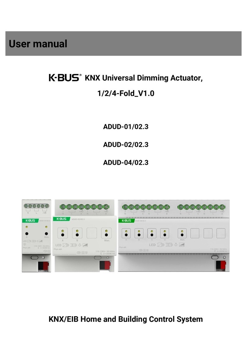
GVS KNX K-BUS BTIS-04/00.1 User manual

GVS K-BUS○
RKNX/EIB IR Emitter & IR Learner
2
www.video-star.com.cn marketing@video-star.com.cn Tel.:(8620)39338986
Fax:(8620)39338465
Version to upgrade (Required)
Version
Upgrade Instructions
Date
User manual-Ver2
After upgrading the software on the user interface with a
legacy of great changes, in order to better use the
upgraded software, it is recommended for the first time
using this software users read the manual.
2013/12/12
User manual-Ver2.1
The main changes are as follows:
1 Description of the type 4bit Function(See 3.3.6);
2 The demo of IR transmitter (See 4.4.2);
3 Description of the current detection(See 3.3.4),
Note: Function not implemented.
2014/05/26
User manual-Ver2.2
The main changes are as follows:
1. Since 4bit is not supported, the description of the
4-bit data type is deleted;
2. Deleted the relevant description of current detection;
3. The arrangement of the chapter contents was
adjusted, and the technical data, circuit diagrams and
dimension diagram of the product had been added. The
title of the manual was changed to IR Emitter & IR
Learner from IR Configuration Tool.
2018/11/02

GVS K-BUS○
RKNX/EIB K-BUS Tool
3
www.video-star.com.cn marketing@video-star.com.cn Tel.:(8620)39338986
Fax:(8620)39338465
Contents
1. General-------------------------------------------------------------------------------------------------------------------------------- 5
2. Technical data------------------------------------------------------------------------------------------------------------------------6
2.1 The IR Learner-------------------------------------------------------------------------------------------------------------------6
2.2 The PC Software---------------------------------------------------------------------------------------------------------------- 6
2.3 The IR Emitter (BTIS-04/00.1)-----------------------------------------------------------------------------------------------7
2.4 The IR Emitter (BTIS-01/00.1)-----------------------------------------------------------------------------------------------8
3. Dimension and Circuit diagram-------------------------------------------------------------------------------------------------9
3.1 Dimension diagram------------------------------------------------------------------------------------------------------------- 9
3.2 Circuit diagram-----------------------------------------------------------------------------------------------------------------10
4. Software Introduction------------------------------------------------------------------------------------------------------------ 12
4.1 Software Interface------------------------------------------------------------------------------------------------------------- 12
4.2 Main menu---------------------------------------------------------------------------------------------------------------------- 12
4.2.1 [File]----------------------------------------------------------------------------------------------------------------------- 12
4.2.2 [View]--------------------------------------------------------------------------------------------------------------------- 13
4.2.3 [Help]---------------------------------------------------------------------------------------------------------------------- 13
4.2.4 [语言(Language)]------------------------------------------------------------------------------------------------------- 14
4.3 Debug Window-----------------------------------------------------------------------------------------------------------------14
4.3.1 Information input-------------------------------------------------------------------------------------------------------- 15
4.3.2 Information display----------------------------------------------------------------------------------------------------- 16
4.4 IR configuration----------------------------------------------------------------------------------------------------------------17
4.4.1 Device manager----------------------------------------------------------------------------------------------------------17
4.4.2 IR learning Code manager--------------------------------------------------------------------------------------------- 17
4.4.3 Appliance function detailed list--------------------------------------------------------------------------------------- 18
4.4.4 The device command configuration box---------------------------------------------------------------------------- 18
4.4.5 Device command library----------------------------------------------------------------------------------------------- 19
4.4.6 Group configuration-----------------------------------------------------------------------------------------------------19
4.5 The download window------------------------------------------------------------------------------------------------------- 20
4.6 Error list------------------------------------------------------------------------------------------------------------------------- 21
5. Demo----------------------------------------------------------------------------------------------------------------------------------22
5.1 Communication settings------------------------------------------------------------------------------------------------------22
5.2 IR configuration function---------------------------------------------------------------------------------------------------- 23
5.2.1 New Controlled appliance--------------------------------------------------------------------------------------------- 23
5.2.2 New IR transmitter------------------------------------------------------------------------------------------------------ 26
5.2.3 Error correction---------------------------------------------------------------------------------------------------------- 29
5.2.4 Download----------------------------------------------------------------------------------------------------------------- 29

GVS K-BUS○
RKNX/EIB K-BUS Tool
4
www.video-star.com.cn marketing@video-star.com.cn Tel.:(8620)39338986
Fax:(8620)39338465
5.2.5 Debug----------------------------------------------------------------------------------------------------------------------29
5.2.6 Import\Export IR learning encoding data--------------------------------------------------------------------------- 29
5.3 Security settings----------------------------------------------------------------------------------------------------------------31
5.3.1 Encryption---------------------------------------------------------------------------------------------------------------- 31
5.3.2 Change Password-------------------------------------------------------------------------------------------------------- 31
5.4 The language switching------------------------------------------------------------------------------------------------------ 31
5.5 Precautions----------------------------------------------------------------------------------------------------------------------32
6. Appendix 1 Device Command execution process--------------------------------------------------------------------------33
7. Appendix 2 The response process of IR Emitter receiving the group telegram------------------------------------35

GVS K-BUS○
RKNX/EIB IR Emitter & IR Learner
5
www.video-star.com.cn marketing@video-star.com.cn Tel.:(8620)39338986
Fax:(8620)39338465
1. General
We call it “IR Learning” that combine the three parts, PC Software, IR Learner and IR Emitter.
The IR Learning can be used for learning control code of the IR Remote Controller, and storing the
code to the database in the PC software. The learned control code can be stored, deleted or tested in
the software.
The IR Emitter has BTIS-04/00.1 and BTIS-01/00.1. The BTIS-04/00.1 has 4 channels.
Usually, we use one channel to control one IR Remote Control device. The IR Learning can learn
up to 64 functional control codes for each channel. However, the BTIS-01/00.1 supports 360 degree
full direction transmitting, and support up to 256 IR codes control.
The IR Learning is consist of PC Software, IR Learner and IR Emitter.
The PC Software is used for config the functions, like physical address, group address, scense
call, etc.
IR Learner is connected to the PC via USB interface and used to learn the control codes of the
keys of the IR Remote Controller. The learning process is realized by operating the software, and
you should put the IR emitter on the remote control near to IR detector on the IR Learner as close as
you can to avoid the failure of learning.
The IR Emitter is connected to the EIB/KNX bus directly using the EIB bus connection
terminal. As the configuration has been finished, the PC software can download the learned control
code to the IR Emitter via the KNX downloader, which has been connected to the KNX/EIB bus.
After success to download, the IR Emitter can control the switch, wind speed and timing of a fan, as
well as the IR remote control devices, such as DVD, TV, Air-Condition, Fan, etc. through sending
telegrams on the KNX bus by other devices in the EIB/KNX system.
This manual provides detailed technical information about the IR Learning for users as well as
assembly and programming details, and explains how to use the IR Learning by the application
examples.
The functions of the IR Learning are summarized as follows:
Supports the IR Emitter of BTIS-04/00.1 and BTIS-01/00.1 versions ;
The device manager of IR can be configured with 20 IR Emitter devices at most ;
The device manager of IR Learning code can be configured with 40 controlled appliances ;
Each of the controlled appliance can learn 40 key encoding at most ;
Each devices have 4 channels, and can configure 256 commands ; (maybe the
BTIS-01/00.1 can support more devices,but max. number of commands still are 256)

GVS K-BUS○
RKNX/EIB K-BUS Tool
6
www.video-star.com.cn marketing@video-star.com.cn Tel.:(8620)39338986
Fax:(8620)39338465
Each channel can be configured with 16 group addresses at most ;
To learn more than 95% of remote controller in the market ;
The IR control commands can be assigned to 2 types of object(1bit 1byte), 1bit object can
recall the IR control commands of the devices, but 1byte object only can recall the
corresponding IR control commands of channel through the scene mode;
Sending time and sending delay can be set for per IR commands ;
Each command can include 5 slave functions, this way is suitable for controlling several
functions via one command at a time ;
2. Technical data
2.1 The IR Learner
The IR Learner uses a common USB port to communicate, it is easy to learn the functional
control codes of the IR remote controller and store the codes to the database of the PC Software
The design of the IR Learner is as a UDisk, small and exquisite in size. The IR Learner is
needed to use only when it learns the functional control codes of the IR remote controller.
Attention: When learning, please put the IR emitter on the remote control near to IR
detector on the IR Learner as close as you can(within 3cm) to avoid the failure of learning.
The IR Learner is provided with receiving and emitting IR function, so it can test and verify
whether the learned control code has been learned correctly.
For convenient to operate, suggest that connect the IR Learner to PC via a USB extension cord
please.
2.2 The PC Software
K-BUS Tool is PC configuration software to configure some devices from video-star, below
describes the overall framework of the software and the use of IR configuration function. The IR
configuration function of this software are only available in conjunction with the IR Learner and IR
Emitter.In addition, the software also provides configuration debugging capabilities, you can avoid
ETS software configure device debugging steps , greatly improve the work efficiency.
The Debug function are summarized as follows:
Used to send the message of group address and monitor the group address message on the

GVS K-BUS○
RKNX/EIB K-BUS Tool
7
www.video-star.com.cn marketing@video-star.com.cn Tel.:(8620)39338986
Fax:(8620)39338465
bus.
Only support to send a type of 1bit , 1byte message;
Support group address message series [write] cycle transmission;
Support group address message series [read] cycle transmission;
Support the manual transmission of group address message;
Can store 10 different message series;
Each series can add 150 test data (including the delay and group address message).
Operating system:the operating system version of Windows XP(32bit) Windows 7(32/64bit)
and Windows 8;
Operating environment:must install "FalconRuntime v2.2.msi" run time library on the PC .
2.3 The IR Emitter (BTIS-04/00.1)
The extremely compact design enables the IR Emitter to be inserted into a conventional 60 mm
or 86mm wiring box.
Attention: the Infrared emitter of the IR Emitter must be installed in range that the IR device
can detect normally, to avoid no action.
Power supply
Bus voltage
21~30V DC, via the EIB bus
Standby current
<8mA
Dynamic current
<20mA
Power consumption
<240mW
Output
Channel Number
4 Channels
Max. transmitting distance
2m
IR wavelength
940nm
IR emission&receiving angle
<45°
Operating and
display
Red LED and button
For assignment of the physical address
Green LED flashing
Indicate the device running normally (OK)
Connections
EIB/KNX
Bus connecting terminal (black/red)
Infrared emitter cable
<10m
Temperature
Operation
– 5 °C ... 45 °C

GVS K-BUS○
RKNX/EIB K-BUS Tool
8
www.video-star.com.cn marketing@video-star.com.cn Tel.:(8620)39338986
Fax:(8620)39338465
range
Storage
– 25 °C ... 55 °C
Transport
– 25 °C ... 70 °C
Mounting
Flush mounted
In wiring box, 60mm×60mm or 86mm×86mm
Dimensions
the IR Emitter 46mm×46mm×11.7mm
the IR Learner 52.5 mm×18.1mm×9.3mm
Weight
0.05kg
2.4 The IR Emitter (BTIS-01/00.1)
Power supply
Bus voltage
21-30V DC,via the EIB
Current consumption
Max. 12mA
Power consumption
Max. 360mW
Auxiliary Power
Work voltage
12-30V DC
Auxiliary current
<200mA
Auxiliary power consumption
<6W
Output
Infrared wave
940nm
Distance
radius:4m~5m
Installation
Mounting
Height Max.4m
Connections
EIB/KNX
Via bus connecting terminal
Operation and
display
Red LED and push button
For assigning the physical address
Green LED flashing
For displaying application layer running
normally
Temperature
Operation
–5 °C ... + 45 °C
Storage
–25 °C ... + 55 °C
Transport
– 25 °C ... + 70 °C
Environmental
humidity
<93%,except condensation

GVS K-BUS○
RKNX/EIB K-BUS Tool
10
www.video-star.com.cn marketing@video-star.com.cn Tel.:(8620)39338986
Fax:(8620)39338465
3.2 Circuit diagram
Fig.(1) IR Emitter (BTIS-04/00.1)
1KNX / EIB bus terminal
2Red LED for entering the physical address, green LED for application layer normally work
3Programming button
4Connectors for Infrared emitter cable
Fig. (2) IR Learner (BTIL-01/00.2)
1USB commnication port
2IR detector. When learning, please put the IR emitter on the remote control near to IR detector on the IR
Learner as close as you can

GVS K-BUS○
RKNX/EIB K-BUS Tool
11
www.video-star.com.cn marketing@video-star.com.cn Tel.:(8620)39338986
Fax:(8620)39338465
1KNX / EIB bus connection terminal
2Auxiliary power supply connection terminal
3Programming push button
4Programming LED, red LED light up for assignment of physical address,
Green LED flashes for indicator of the device running normally
5Installation height :Max.4m
6Transmit radius:4m~5m
H
R
⑥
⑤

GVS K-BUS○
RKNX/EIB K-BUS Tool
12
www.video-star.com.cn marketing@video-star.com.cn Tel.:(8620)39338986
Fax:(8620)39338465
4. Software Introduction
The software supports two language: Chinese and English,when under the English operating
system want to normal use Chinese interface, you need to install Chinese language pack .
4.1 Software Interface
Double-click the shortcut on the desktop [K-BUS Tool.exe] or select [Start]/[All
Programs]/[K-BUS Tool]/[K-BUS Tool.exe] to start the software,the initial interface shown as in fig.
4.1.
Fig.4.1 The initial interface
4.2 Main menu
The main menu include three menu group: [file] [view] [help], these menu group content and
method of use will introduce as follow section.
4.2.1 [File]
The drop-down menu shown as fig.4.2.
①[New]: Create a new configuration file;
②[Open]: Open the configuration file;

GVS K-BUS○
RKNX/EIB K-BUS Tool
13
www.video-star.com.cn marketing@video-star.com.cn Tel.:(8620)39338986
Fax:(8620)39338465
③[Security settings]:Set password of current configuration file;
④[Communication]:Software and KNX bus communication settings;
⑤[Recent files]:Browse or open the 10 recent success opened files;
⑥[Quit]:Exit the software.
Fig.4.2 [File] drop-down menu
4.2.2 [View]
The drop-down menu shown as fig.4.3.
①[IR Configuration]:Show IR Configuration window;
②[Download]:Show Download window;
③[Error list]:Show Error list window;
④[Debug]:Show Debug window;
⑤[Toolbar]:Show Toolbar.
Fig.4.3 [View] drop-down menu
4.2.3 [Help]
The drop-down menu shown as fig.4.4.
①[About]:Show the software version number information;
②[User manual]:Open the user manual.
Fig.4.4 [Help] drop-down menu

GVS K-BUS○
RKNX/EIB K-BUS Tool
14
www.video-star.com.cn marketing@video-star.com.cn Tel.:(8620)39338986
Fax:(8620)39338465
4.2.4 [语言(Language)]
The drop-down menu shown as fig.4.5.
①[Similified Chinese]:Select simplified Chinese as the software display language next times;
②[English]:Select simplified English as the software display language next times.
Fig.4.5 [语言(Language)] drop-down menu
4.3 Debug Window
The debug window shown as fig.4.6,it is similar to ETS4's "Group Monitoring" window,but
the functions of debug window would be far less than the functions of ETS's "Group Monitoring",
therefore,to obtain more detailed information we need to use the ETS4 "Group Monitoring" window
for the test.Debugging is mainly to write or read the device's group data by sending a group
telegram, then the user according to the feedback information and the response of controlled
appliances to judge the downloaded in the device configuration is in force or not.
Fig.4.6 Debug Window
The debug window includes information input box (fig.4.6 the gray background area) and
information feedback box(fig.4.6 the dark background area).These informations are described in the
following subsections.

GVS K-BUS○
RKNX/EIB K-BUS Tool
15
www.video-star.com.cn marketing@video-star.com.cn Tel.:(8620)39338986
Fax:(8620)39338465
4.3.1 Information input
There are two kinds of group telegram sending mode [manually send, circular sent (write /
read)] in the information input box:
①Manual to send:
Group address:The group address of mailing telegram ;
Priority:The priority of sending Group telegram on the bus;
Button "...":Browse all input record of the group address;
Data type:The data type of group telegram ;
Value:The value of group telegram ;
Button "Write":To send the telegram which write group information;
Button "Read":To send the telegram which read group information;
Delay: Delay time of telegram sending after click the button "write/read".
②Circular sent (write / read)
(1)Loop to write
Times: The sending times of group address telegram series;
Button "+": Pop up a dialog box of adding group address series(Shown as fig.4.7).
Fig.4.7 Group list dialog box-write

GVS K-BUS○
RKNX/EIB K-BUS Tool
16
www.video-star.com.cn marketing@video-star.com.cn Tel.:(8620)39338986
Fax:(8620)39338465
Through the dialog can add and save 10 cycling test series,each series can add 150 group
telegram.When the cycling send start,the debug window will according to the telegram which was
stored by the current test sequence, and according to the serial number in turn send the telegram.
(2)Loop to read
Times: The sending times of group address telegram series;
Button "+": Pop up a dialog box of adding group address series(Shown as fig.4.8,details
please see page Loop to write).
Fig.4.8 Group list dialog box-Read
4.3.2 Information display
Number:The sequence number of Feedback message ;
Time:The time of detecting message ;
Message:The information of feedback message;
Priority: The Priority of telegram ;
Group address:The group address of telegram ;
Value:the value of telegram ;
Rount count:The routing count of telegram .

GVS K-BUS○
RKNX/EIB K-BUS Tool
17
www.video-star.com.cn marketing@video-star.com.cn Tel.:(8620)39338986
Fax:(8620)39338465
4.4 IR configuration
IR configuration window is used to configure the function of IR Emitter, the contents of the
window as shown in fig.4.9. Through IR Learning Code Manager, we can learn and record each IR
encoding of the appliance remote controller's function ,and can config the key function encoding
into the commands library by the commands configuration box, according to a certain format
configured to the command which IR Emitter can call, then through the group configuration box
you can config the group address of channel function, the command to call and so on. Finally
downloaded the configuration to the IR Emitter via the KNX Bus.
fig. 4.9 IR Configuration
4.4.1 Device manager
The device manager is a mechanism to manage the configurated information of IR Emitter, it
is mainly used for device of new, delete,modify the properties, channel selection, download of the
configurated information.
4.4.2 IR learning Code manager
IR learning Code Manager is a mechanism to manage the information of the controlled
appliances which have IR remote controlled function, it is mainly used for the controlled electrical
new, delete, rename, import or export IR learning code, and the remote controlled function of
Channel A, B, C, D group configuration box and device command
library list
Appliance function detailed list
The device commands
configuration box
IR device manager
IR learning code
manager

GVS K-BUS○
RKNX/EIB K-BUS Tool
18
www.video-star.com.cn marketing@video-star.com.cn Tel.:(8620)39338986
Fax:(8620)39338465
appliance’s new and learning, test.
4.4.3 Appliance function detailed list
The appliance function detailed list is used to display the item sub information which are
selected by the learning code manager. we can check the appliance name of selected items,
electrical function, the frequency and pulse counting of the electrical function remote controller,
also can pass the test to verify the effectiveness of learning code.
4.4.4 The device command configuration box
Device command box is divided into four parts: learning code, the main command, the list of
Attached commands and command marks.
①Learning Code (Choice in the appliance function detailed list)
Appliance:The electrical which the main command calls the electrical function;
Appliance function:the main command calls the electrical function;
②Main command
Channel:Part of a command;
Scene:Part of a command;
Send time: The number of send command,for example, the wind speed function of a fan is set
to 2 times for transmitting, then when the transmitter receives a corresponding telegram, the
transmitter will send the wind speed signal to the fan and continuous send 2 times, then the wind
speed of the fan will jump 2 steps.
Send delay:To set the send delay for the command. For example, you turn on a fan, and attach
a pivot and time function. If they are executed at the same time, this may influence the life of the
fan motor,so you can delay a period of time for transmitting of the pivot and time function. Then
when the transmitter receives a 14 corresponding telegram, the transmitter will first send the open
function signal to the fan, after a while send the pivot function signal to the fan, and then after a
time send the time function signal to the fan, in order to protect the motor of the fan.
③the list of from commands
Channel:Part of a command;
The scene:Part of a command;
Button">>":Add a from command;
Button"<<":Delete the from command of selected.

GVS K-BUS○
RKNX/EIB K-BUS Tool
19
www.video-star.com.cn marketing@video-star.com.cn Tel.:(8620)39338986
Fax:(8620)39338465
④Command marks.
Device:The device of the current configuration command;
Command:The mark of current command;
Button"Add command"or"Modify command" :Add new command or modify the old
command;
"Automatic naming":Selected whether or not automate name for the device command.
4.4.5 Device command library
Select the tab [Command Library] in the red box of group configuration shown in Figure 4.10
the detailed list of device command Library.The detailed list of device command library shows all
the commands’parameters which are configurated for the device by the user,Its main parameters
had detail introduced in the previous subsection ,so this section do not introduce anymore.
Fig.4.10 The detailed list of device command Library
4.4.6 Group configuration
In the group configuration, users can configure every channel’s the group address allocation,
command calling details, scene configuration and other data of the devices.
Number:Each function’s serial number (automatic sorting)
Function:Assigned the only non empty marking to the function;
Data Type:Functional data type including 1Bit, 1Byte, when choose 1Bit, the parameters of
[Value=1] and [Value=0] effective, When choose 1Byte, calling all command of the channel by
using scene recall.
Value=1:Setting the data type is 1Bit case, device receives the command which was called by
the specified message value 1;
Value=0:Setting the data format is 1Bit case, device receives the command which was called
by the specified message value 0;

GVS K-BUS○
RKNX/EIB K-BUS Tool
20
www.video-star.com.cn marketing@video-star.com.cn Tel.:(8620)39338986
Fax:(8620)39338465
Description:The described information of the function;
The Save button:The function of save the current editor
4.5 The download window
Fig.4.11 the download window
Choose the main menu bar [view] menu group drop-down menu [Download], pop up as shown
in Figure 4.11 the download window when it is executing the download tasks.It can receive and
perform the download task of other window, and each can only perform a download task.Users can
cancel the current task’s execution and view the information and schedule of the current task and
task record By downloading Windows .
This manual suits for next models
2
Table of contents
Other GVS Controllers manuals
Popular Controllers manuals by other brands

Trinamic
Trinamic TMCM-6110 Firmware user manual

Jetec
Jetec ISOMOVE Use and maintenance guide

Johnson Controls
Johnson Controls tyco Power Pro Series Reference manual

Grundfos
Grundfos LLC 1000W Installation and operating instructions

Elotech
Elotech R 1140 operating manual

PS Automation
PS Automation PSF Series operating instructions

Kutai electronics
Kutai electronics ADVR-053 Operation manual

Mitsubishi Electric
Mitsubishi Electric MELSERVO-J5 MR-J5-G Series user manual

Sven
Sven VR-P5000 manual

Siemens
Siemens OpenAir manual

Sentera Controls
Sentera Controls MT Mounting and operating instructions

Artecta
Artecta Domotion DLC-4 RGB manual