2
1. Table of contents
1. Table of contents............................................................................................................................. 2
2. Safety regulations............................................................................................................................ 4
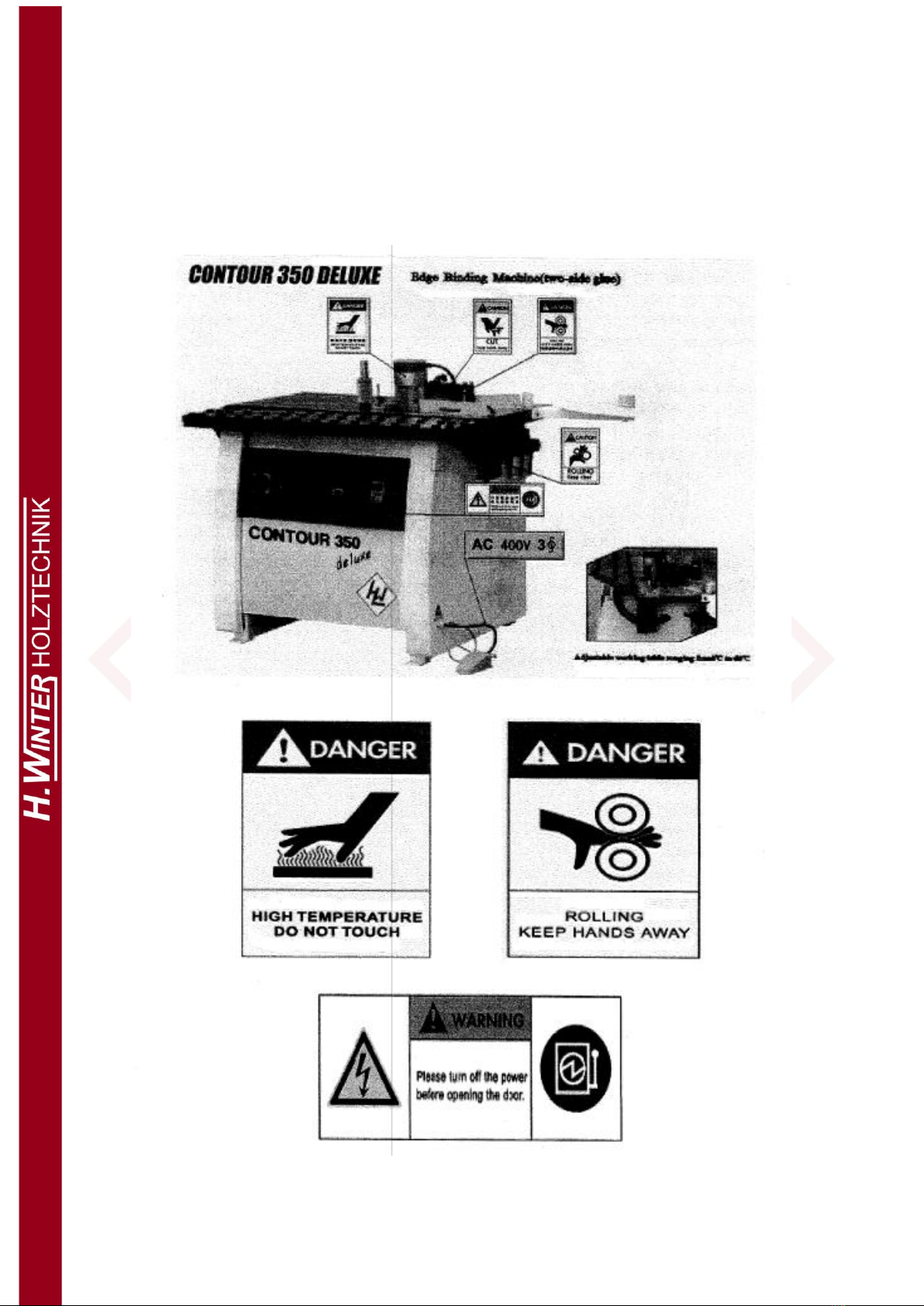
2.1. Warning picture............................................................................................................................ 4
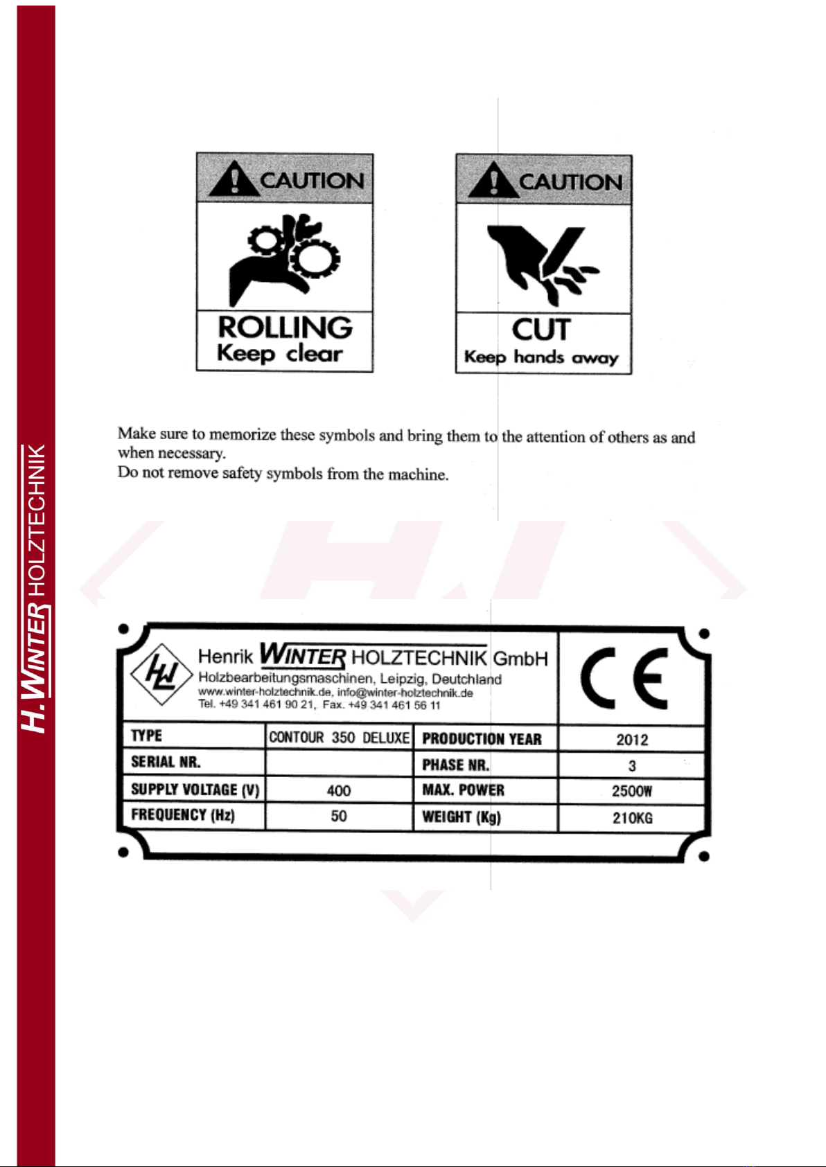
2.2. Name plate .............................................................................................................................. 5
2.3. Warning ................................................................................................................................... 6
3. Overview.......................................................................................................................................... 7
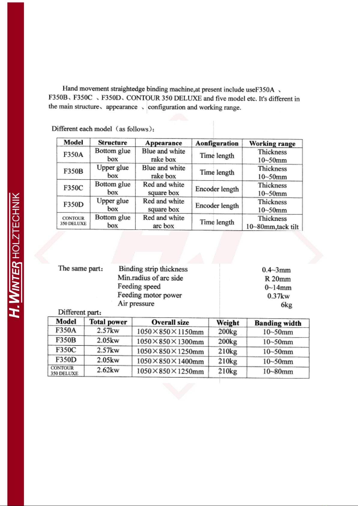
3.1. Different each model............................................................................................................... 7
3.2. Main specifications.................................................................................................................. 7
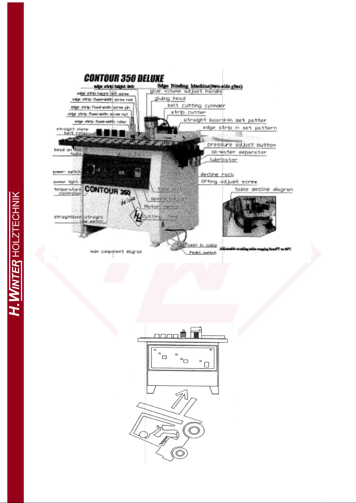
4. Main part schematic........................................................................................................................ 8
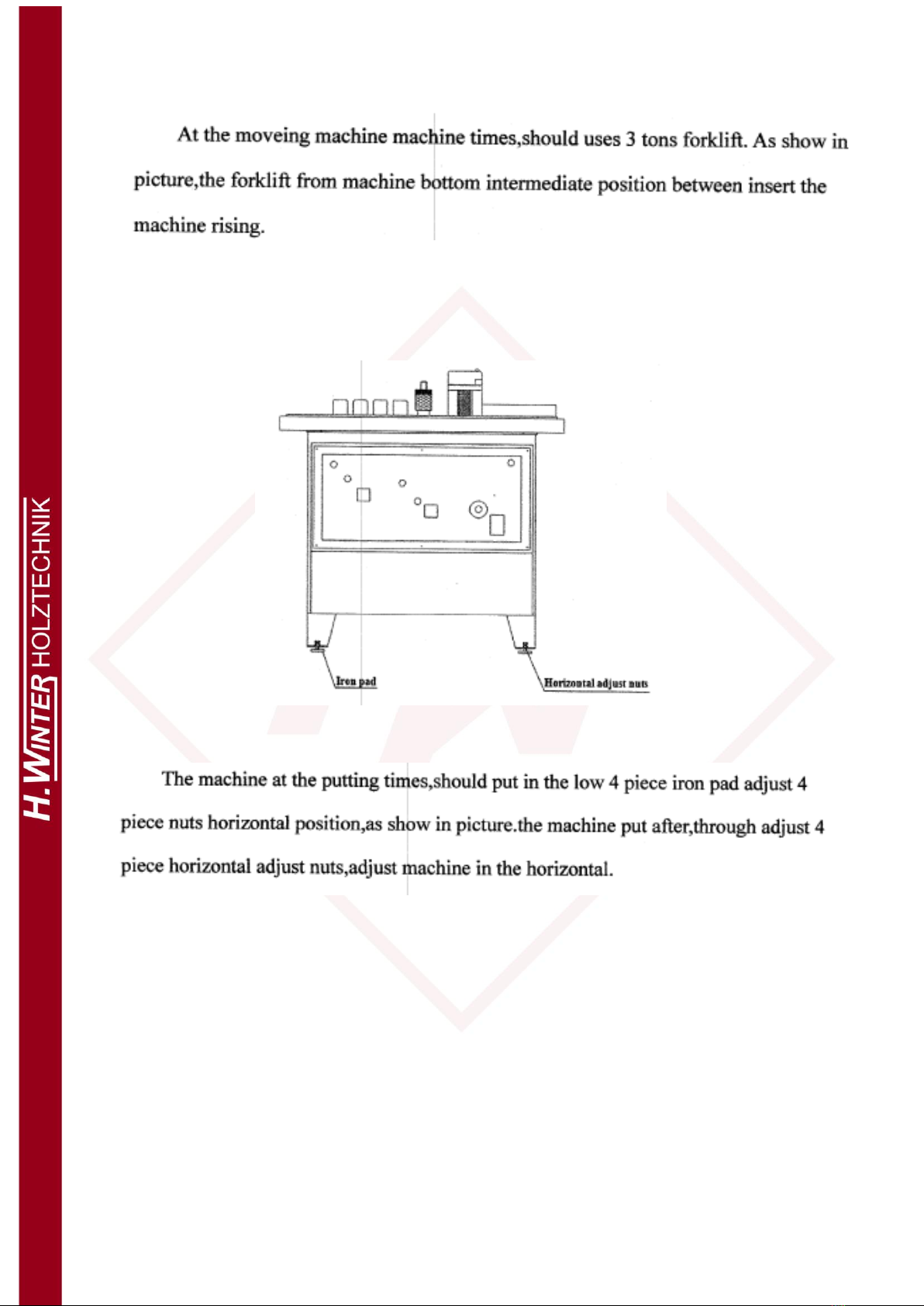
4.1. Handling and install part ......................................................................................................... 8
4.1.1. Handling........................................................................................................................... 8
4.2. Calibration ........................................................................................................................... 9
4.3. Power and high air pressure.................................................................................................. 10
5. Installation and wiring................................................................................................................... 11
5.1. Overall size picture ................................................................................................................ 11
5.2. Machine put postion picture................................................................................................. 11
5.3. Install ..................................................................................................................................... 12
5.4. Wiring .................................................................................................................................... 12
6. Adjustment and operation ............................................................................................................ 13
6.1. Adjust..................................................................................................................................... 13
6.1.1. Sideband position.......................................................................................................... 13
6.1.2. Adjust pressure belt wheel and glue roller parallel with relative position ................... 14
6.1.3. Adjusts the height limit nuts ......................................................................................... 15
6.2. Operation .............................................................................................................................. 15
6.2.1. Straight edge binding .................................................................................................... 16
6.2.2. Curve edge binding........................................................................................................ 16
7. Electrical part................................................................................................................................. 17
7.1. Control panel......................................................................................................................... 17
7.2. Electrical diagram .................................................................................................................. 18
8. Pneumatic part .............................................................................................................................. 19
8.1. Pneumatic diagram ............................................................................................................... 19