manuals.online logo
Brands
  1. Home
  2. •
  3. Brands
  4. •
  5. Opus
  6. •
  7. Binding Machine
  8. •
  9. Opus MB 300 User manual

Opus MB 300 User manual

Other manuals for MB 300

1

Other Opus Binding Machine manuals

Opus TB 250 User manual

Opus

Opus TB 250 User manual

Opus profiBINDER&CLOSER User manual

Opus

Opus profiBINDER&CLOSER User manual

Opus Atlas 300 mono User manual

Opus

Opus Atlas 300 mono User manual

Opus Atlas 190 User manual

Opus

Opus Atlas 190 User manual

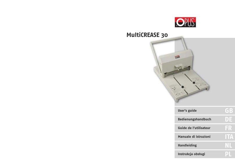
Opus MultiCREASE 30 User manual

Opus

Opus MultiCREASE 30 User manual

Opus Atlas 300 mono User manual

Opus

Opus Atlas 300 mono User manual

Opus Atlas 300 mono User manual

Opus

Opus Atlas 300 mono User manual

Opus MBE-300 User manual

Opus

Opus MBE-300 User manual

Opus Atlas 300 mono User manual

Opus

Opus Atlas 300 mono User manual

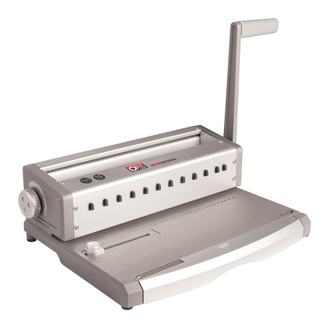
Opus Wire Bono User manual

Opus

Opus Wire Bono User manual

Opus Hercules Plus User manual

Opus

Opus Hercules Plus User manual

Opus MB 300 el-office User manual

Opus

Opus MB 300 el-office User manual

Opus MB 300 User manual

Opus

Opus MB 300 User manual

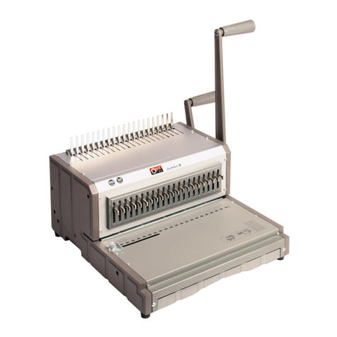
Opus El Jumbo B User manual

Opus

Opus El Jumbo B User manual

Opus JUMBO B User manual

Opus

Opus JUMBO B User manual

Opus MultiPress 52 User manual

Opus

Opus MultiPress 52 User manual

Opus profiBINDER&CLOSER User manual

Opus

Opus profiBINDER&CLOSER User manual

Opus Atlas 150 User manual

Opus

Opus Atlas 150 User manual

Opus multiCREASE 52 User manual

Opus

Opus multiCREASE 52 User manual

Opus OFFICERINO User manual

Opus

Opus OFFICERINO User manual

Opus Easy 120 User manual

Opus

Opus Easy 120 User manual

Opus Wire Bono User manual

Opus

Opus Wire Bono User manual

Opus Atlas 190 User manual

Opus

Opus Atlas 190 User manual

Opus MBE-300 User manual

Opus

Opus MBE-300 User manual

Popular Binding Machine manuals by other brands

Tamerica OPTICOMBO-341 quick start guide

Tamerica

Tamerica OPTICOMBO-341 quick start guide

GBC CombBind A20 instruction manual

GBC

GBC CombBind A20 instruction manual

GBC CombBind C800pro instruction manual

GBC

GBC CombBind C800pro instruction manual

JBI Alpha-Doc MKIII instruction manual

JBI

JBI Alpha-Doc MKIII instruction manual

GBC DocuBind P100 operating instructions

GBC

GBC DocuBind P100 operating instructions

Rexel CB345E Service and parts manual

Rexel

Rexel CB345E Service and parts manual

Morgana DigiBook 450 Technical manual

Morgana

Morgana DigiBook 450 Technical manual

GBC C210 instruction manual

GBC

GBC C210 instruction manual

Fellowes Orion-E 500 manual

Fellowes

Fellowes Orion-E 500 manual

Fellowes Pulsar E 300 instructions

Fellowes

Fellowes Pulsar E 300 instructions

GBC Modular MP2500iX operating instructions

GBC

GBC Modular MP2500iX operating instructions

Qupa M600 Manual instruction

Qupa

Qupa M600 Manual instruction

Rollabind PBS 2000 operating instructions

Rollabind

Rollabind PBS 2000 operating instructions

GBC SureBind 500 instruction manual

GBC

GBC SureBind 500 instruction manual

ibico ibiMaster 250 instruction manual

ibico

ibico ibiMaster 250 instruction manual

Peach Starbinder Pro PB200-30 operating instructions

Peach

Peach Starbinder Pro PB200-30 operating instructions

Fellowes Starlet 90 instruction manual

Fellowes

Fellowes Starlet 90 instruction manual

Peach PB200-70 operating instructions

Peach

Peach PB200-70 operating instructions

manuals.online logo
manuals.online logoBrands
  • About & Mission
  • Contact us
  • Privacy Policy
  • Terms and Conditions

Copyright 2025 Manuals.Online. All Rights Reserved.

User Guide
EN
Bedienungshandbuch
DE
Guide de l’utilisateur
FR
Инструкция по эксплуатации
RU
Instrukcja obsługi
PL
Manual de usuario
ES
Návod k použití
CZ
Manuale di istruzioni
IT
MB 300
MB 300
2
Contents:
1 METALBIND SYSTEM
2 DESCRIPTION
3 HEALTH & SAFETY
4 PrREPARATION TO WORK
5 PRESSURE INDICATOR
6 BINDING (METALBIND)
7 DE-BINDING (METALBIND)
8 C-BIND SYSTEM
9 TECHNICAL DATA
1 - the back wall of the channel is bent to clamp covers and pages
2 - special covering for hot print stamping
3 - shaped front edge to keep a perfected flat face to the front of the presentations
4 - the internal pages protected against damage by the covers from the channel
5 - the front face of the channel is never misshaped always flat
6 - the special protrusions at each end help to centre covers and papers
of the presentation document and stop them moving sideways in the channel
Metalbind
1
2
3
4
5
6
1METALBIND SYSTEM
MB WAS DESIGNED FOR BINDING DOCUMENTS AND COVERS USING THE METAL
BIND SYSTEM OF COVERS AND CHANNELS. THE PAGES OF THE PRESENTATION DOCU
MENT ARE PLACED BETWEEN COVERS AND THEN PUT INTO THE METALBIND CHANNEL
AND CLAMPED TOGETHER FROM THE OUTSIDE.
Contents:
METALBIND SYSTEM
DESCRIPTION
HEALTH & SAFETY
SYMBOLS
PREPARATION TO WORK
PRESSURE INDICATOR
BINDING (METALBIND
DE-BINDING (METALBIND)
C-BIND SYSTEM
TECHNICAL DATA
MB 300 WAS DESIGNED FOR BINDING DOCUMENTS AND COVERS USING THE METALBIND
SYSTEM OF COVERS AND CHANNELS. THE PAGES OF THE PRESENTATION DOCUMENT ARE
PLACED BETWEEN COVERS AND THEN PUT INTO THE METALBIND CHANNEL AND CLAMPED
TOGETHER FROM THE OUTSIDE.
1 - The back wall of the channel is bent to clamp covers and pages
2 - Special covering for hot print stamping
3 - Shaped front edge to keep a perfected flat face to the front of the presentations
4 - The internal pages protected against damage by the covers from the channel
5 - The front face of the channel is never misshaped always flat
6 - The special protrusions at each end help to centre covers and papers
of the presentation document and stop them moving sideways in the channel
METALBIND SYSTEM
1
2
3
4
5
6
7
8
9
10
1
Contents:
1 METALBIND SYSTEM
2 DESCRIPTION
3 HEALTH & SAFETY
4 PrREPARATION TO WORK
5 PRESSURE INDICATOR
6 BINDING (METALBIND)
7 DE-BINDING (METALBIND)
8 C-BIND SYSTEM
9 TECHNICAL DATA
1 - the back wall of the channel is bent to clamp covers and pages
2 - special covering for hot print stamping
3 - shaped front edge to keep a perfected flat face to the front of the presentations
4 - the internal pages protected against damage by the covers from the channel
5 - the front face of the channel is never misshaped always flat
6 - the special protrusions at each end help to centre covers and papers
of the presentation document and stop them moving sideways in the channel
Metalbind
1
2
3
4
5
6
1METALBIND SYSTEM
MB WAS DESIGNED FOR BINDING DOCUMENTS AND COVERS USING THE METAL
BIND SYSTEM OF COVERS AND CHANNELS. THE PAGES OF THE PRESENTATION DOCU
MENT ARE PLACED BETWEEN COVERS AND THEN PUT INTO THE METALBIND CHANNEL
AND CLAMPED TOGETHER FROM THE OUTSIDE.
1 - Handle
2 - Clamp lever
3 - Binding slot
4 - De-binding hooks
5 - Extended back support
6 - Main back support for adjustable
end stops and de-binding plate
7 - Channel size selector tool
8 - Fixed end stop
9 - Adjustable end stop
10- De-binding wedge (MB),
11- De-Binding Adapter for channels
1.5 and 3mm only
12- Storage slots for binding bars A & B
and de-binding wedge
A - Binding bars thin
B - Binding bars thick
C - Fixed cover guide
D - Channels 1.5 to 32 mm
E - Binding jaw
• Before operating the equipment read the Health & Safety precautions and
manufacturer recommendations and the operation manual.
• The operation manual should be easily available at any time for the operator.
• The equipment should be kept away and out of reach of children.
• Equipment must be protected against dust and damp.
• Equipment must be positioned on a strong and strudy flat surface.
• While binding, do not put fingers into the binding slot.
• Be careful when moving the equipment (very heavy).
• Take care binding tools can slide out of the Storage slots (HEAVY) !
• Pay attention to sharp edges of the de-binding wedge.
• The machine must not be used for any other purposes other than those indicated
in the operating manual.
• It is necessary to check and supervise if the equipement being operated correctly
In case of any malfunctions before, contacting the service department or dealer.
• Equipment must not be located outside
• Equipment must be operated in accordance with the general Health & Safety rules.
• Repairs must be carried out by authorized sta during the guarantee period.
• Always leave the handle (1) in the open position.
DESCRIPTION
2
HEALTH & SAFETY
3
MB 300 •User guide EN
3
A/B C
1
2
4
5
A/B
12
A
B
10
10
9
3
8
69
3
78b
11
Atlas 190 • User’s guide GB
3
DESCRIPTION2
1 - bind and de-binding handle
2 - clamp lever
3 - binding slot
4 - de-binding hooks
5 - De-binding wedge (MB), de-Binding
Adapter for channels 1.5 and 3mm only
6 - channel width selecting tool
7 - front bar of the COVERguide system
8 - back bar of the COVERguide
system with ruler
9 - fixed side stop
10 -adjustable side stop
11 - extended back support
HEALTH & SAFETY
• Before operating the equipment read the Health & Safety
precautions, manufacturers recommendations and the
operation/user manual
• The operation/user manual should be easily available at any
time for the operator
• The equipment must be kept away and out of reach
of children
• Equipment must be protected against dust and damp
and should be positioned on a strong and sturdy flat surface
• While binding, do not put fingers into the binding slot
• Be careful when moving the equipment it is very heavy
• Pay attention the de-binding wedge has sharp edges
• The machine must not be used for any other purposes
16
13
10
7
MINI
6
5
7
11
10
10
9
4
4
8
37
3
2
1
8b
16
13
10
7
MINI
16
13
10
7
MINI
8b 8
7
16
13
10
7
MINI
• Przed rozpoczęciem pracy z urządzeniem należy zapoznać się z zasadami bezpieczeństwa,
zaleceniami producenta i instrukcją obsługi. Instrukcję tę należy zachować i korzystać
z niej w przypadku jakichkolwiek wątpliwości dotyczących obsługi urządzenia.
• Urządzenie należy chronić przed wilgocią i kurzem.
• Urządzenie należy trzymać poza zasięgiem dzieci.
• Urządzenie należy ustawić na stabilnej powierzchni o odpowiedniej wytrzymałości.
• W trakcie zaciskania nie wkładać rąk do szczeliny bindującej!
• Ze względu na wagę klina zachować ostrożność przy przenoszeniu.
• Należy uważać na ostre krawędzie klina do rozbindowywania.
• Nie wolno używać urządzenia do innych celów niż określone w instrukcji obsługi.
ZASADY BEZPIECZEŃSTWA
MB 300 •User’s guide GB
2DESCRIPTION
3
1 - Handle
2 - Clamp lever
3 - Binding slot
4 - De-binding hooks
5 - Extended back support
6 - Main back support for adjustable
end stops and de-binding plate
7 - Channel size selector tool
8 - Adjustable end stop
9 - De-binding wedge tool
10 - De-binding wedge (MB),
de-Binding Adapter for channels
1.5 and 3mm only
11 - Channel slot
A/B - Binding bars
C - Position banding bar
D - D1: channel 5-32
D2: channel 1,5; 3 mm
E - Binding jaw
1
2
10A
10B
11
A/B C
D
E
A/B C
3
4
5
6
8
8
HEALTH & SAFETY
•Before operating the equipment read the Health & Safety precautions
and manufacturer recommendations and the operation manual.
•The operation manual should be easily available at any time for the operator.
•The equipment should be kept away and out of reach of children.
•Equipment must be protected against dust and damp.
•Equipment must be positioned on a strong and sturdy flat surface.
•While binding, do not put fingers into the binding slot.
•Be careful when moving the equipment (very heavy).
•Pay attention to sharp edges of the de-binding wedge.
•The machine must not be used for any other purposes other than those
indicated in the operating manual.
9
4
7
2
3
OPIS URZĄDZENIA
BINDING & DE-BINDING (C-BIND)
Accessories enabling binding and de-binding of covers of the C-BIND system.
•Channel size selector tool (7)
•O•CB Inserts for Atlas 300 / MB 300, two part kit for all covers (dig. 1)
•O•CB Debinding Tool for Atlas 300 / MB 300 / MBE 300 - de-binding wedge (dig. 2) and AA
cover de-binding jig tool (dig. 3)
The bound documentation must have thickness of at least 1,8 mm (without cover). If the
documentation is thinner, it is obligatory to use filling strips (e.g. O•Filling Sticky available
at OPUS), to increase the thickness of bound documents. When using covers up to 16 mm size
(C), put before binding both binding inserts A1 and B1 to the binding slot and when using
covers with size over 16 mm, put only one B1 insert into the binding slot.
Depending on amount of inserts used during binding, position of the bow can be appro-
priately adjusted. If in the binding slot there is only one B1 insert, the bow should be moved
to the front end position, in case of binding by means of two inserts A1 and B1 the extended
back support (5) should be moved to the back end position.
9TECHNICAL DATA
•Binding capacity ............................................................................................up to 300 sheets*
•Net weight ..............................................................................................................19 kg / 41.9 lbs
•Gross weight ..........................................................................................................19.5 kg / 43 lbs
•Dimension (H x W x D) ....................................270 x 530 x 320 mm / 10.6 x 20.8 x 12.6 in
* the tests were made on 80 g/m
2
substance paper 18.03.2015
MB 300 •User’s guide GB
8
channel number of
dimension bound sheets
AA soft cover 15-40
hard cover 20-40
A 41-95
B 96-125
C 126-150
D 151-190
E 191-230
F 231-265
G 266-300
Binding and de-binding of covers of the C-BIND system
is performed analogous to binding with METALBIND system,
but: Measure the thickness of sheet pile to be bound
means of the cover selection tool or the chart and
select appropriate cover.
Important! The AA cover de-binding jig tool included
in the (O.CB Debinding Tool for Atlas 300 / MB 300 / MBE
300) should be fitted on the spine edge of AA cover be-
fore debinding.
B1
Dig 1.
Dig 2.
A1
Dig 3.
Inhalt:
1 METALBIND SYSTEM
2 ÜBERSICHT
3 SICHERHEITSHINWEISE
4 VORBEREITUNG
5 ZEIGER DER BINDESTä
6 BINDUNG (METALBIND)
7 ÖFFNEN EINER BINDUNG (METALBIND)
8 C-BIND SYSTEM
9 TECHNISCHE DATEN
Dies ist eine viel stärkere Bindung,
weil Umschläge und Blätter werden durch einen Kanal gehalten.
1 - Die Rückseite des Kanals ist geneigt, um die Umschläge und Blätter der Dokumentation zu halten
2 - Der Kanal ist ästhetisch mit einem Furnier beklebt
3 - Eine spezielle Form des Kanals garantiert ein perfektes Aussehen der Dokumentation
4 - Die Blätter werden nicht deformiert
5 - Die Vorderseite wird nie derformiert
6 - Spezielle Begrenzer erleichtern eine präzise Zentrierung der Dokumente mit Umschlägen und
machen das Verschieben der Dokumentationsblätter entlang des Kanals unmöglich
1METALBIND SYSTEM
DAS BINDEGERÄT MB VERARBEITET METALBIND SCHIENENBINDERÜCKEN UND
EINBANDDECKEL. DOKUMENTE WERDEN MITHILFE VON SCHIENENBINDERÜCKEN AUS
METALL GEBUNDEN.
Metalbind
1
2
3
4
5
6
MB 300 • Instrukcja obsługi PL
27
A
B
A/B
12 C
1
2
4
5
8
D
7
E
A/B
c
12
11
10
9
3
8
69
3
1 - Ramię urządzenia
2 - Uchwyt regulujący rozwarcie szczęk
3 - Szczelina bindująca
4 - Zaczep
5 - Pałąk
6 - Płyta debindująca
7 - Przyrząd doboru rozmiaru
kanału/okładki
8 - Ogranicznik
9 - Ruchomy ogranicznik
10 - Klin debindujący
11 - Wkładka do debindowania
kanałów 1,5 mm - 3 mm
12 - Wnęki na wkładki bindujące A/B
oraz klin debindujący
A - Wąska wkładka bindująca
B - Szeroka wkładka bindująca
C - Prowadnica Cover guide
D - Kanał 1,5 mm - 32 mm
E - Szczęka bindująca
A
• Unpack the equipment and fit the extended back support (5) on the top of the main back
support plate (6) in the pre-drilled holes with the attached thumb screws supplied.
• Fit the binding handle (1) to the equipment with the Allen key bolt supplied, tighten firmly.
• On the back In the slots (12) of the equipment are two binding bars A & B and the de-bind-
ing wedge (10).
• The tool for selecting the channel size (7) is magnetized so you can keep it on the equip-
ment housing.
• The 2 binding bars A&B and the fixed cover guide have a spacial shape to help you insert
covers and document into the channel.
• Choose a binding A or B, depending on the thickness of the document, and insert it near
the main back support. Chamfered edge pointing into the Centre of the slot.
• A clear view this is shown in point 2 “DESCRIPTION”.
The pressure indicator gives you the facility to save the best pressure for the channel when
binding large numbers of the same presentations/documents giving you a perfect result and
speeding up the job. The LED’s will move up the scale from 1 to 10 when the right binding
pressure you set is reached, you can hear a single sound then release the binding handle.
1. Press START/SET button on the LED display, it will show the last value set.
If this value is good for the next job, you can start binding right away.
2. To set a new binding pressure, press the START/SET button and hold it on until the LED light reaches
the number you wish to set then release the button and the level is set.
3. During binding process, as you increase the pressure with the handle the LED’s move up the scale
until it reaches the level set and makes a single sound release the handle.
4. When you stop binding for over a minute, the unit goes into an energy-saving mode and LED flash,
when it is in this mode you can still bind it will sound when you reach the correct pressure.
5. When the binding equipement is not used for 5 minutes, the pressure unit will turn its self o to save
the battery, to start again just press START/SET button once and continue binding.
CHANGING THE BATTERY
The unit is powered by the CR2032 lithium battery, which is on the right side
on the back of the equipment. When the battery is low the sign at the top
of the scale comes on warning you to change the on the battery the lower
the battery get the faster the light flashes.
See diagram opposite
1. To remove the battery slide it out by using a small thin screwdriver.
2. Slide the new battery in with the plus sign + to the right away from equipment.
*Batteries when empty must be collected separately and cannot be put together with normal type of wastes. Information concerning
collection points for empty batteries are available at your local city or municipal autorities oces or on the internet.
PREPARATION TO WORK
PRESSURE INDICATOR LED DISPLAY UNIT
5
6
4
5
•It is necessary to check and supervise if the equipment being operated correctly
In case of any malfunctions before contacting, the service department or dealer.
•Equipment must not be located outside
•Equipment must be operated in accordance with the general Health & Safety rules.
•Repairs must be carried out by authorized staff during the guarantee period
PREPARATION TO WORK
•Unpack the equipment and fit the extended back support on the top of the main back
support plate in the pre-drilled holes with the screws and Allen key supplied.
•Fit the binding handle to the equipment with the screw and Allen key supplied, tighten
firmly.
•In the slots in back (10) of the equipment are two binding bars and the de-binding wedge.
•Tool for selecting the channel size has a magnet so you can keep it on the equipment hous-
ing.
•The binding guide bars A & B fit at the back of the binding slot by magnetics and has a
scale on each.
The third guide bar fits over the binding jaw. These three bars form the COVERGUIDE SYSTEM
and were specially designed to make it quick and easy to put covers and pagers into the
Metalbind channel for binding. A clear view this is shown in point 2 "DESCRIPTION".
PRESSURE INDICATOR LED DISPLAY UNIT
The pressure indicator gives you the facility to save the best pressure for the channel when
binding large numbers of the same presentations/documents giving you a perfect result and
speeding up the job. The LED,s will move up the scale from 1 to 10 when the right binding
pressure you set is reached, you can hear a single sound then release the binding handle.
1. Press START/SET button on the LED display, it will show the last value set.
If this value is good for the next job, you can start binding right away.
2. To set a new binding pressure, press the START/SET button and hold it on until the LED light reaches
the number you wish to set then release the button and the level is set.
3. During binding process, as you increase the pressure with the handle the LED, s move up the scale
until it reaches the level set and makes a single sound release the handle.
4. When you stop binding for over a minute, the unit goes into an energy-saving mode and LED flash,
when it is in this mode you can still bind and it will sound when you reach the correct pressure.
5. When the binding equipment is not used for 5 minutes, the pressure unit will turn its self off to save
the battery, to start again just press the START/SET button once and continue binding.
CHANGING THE BATTERY
The unit is powered by the CR2032 lithium battery, which is on the right side
on the back of the equipment. When the battery is, low the sign at the top
of the scale comes on warning you to change the on the battery the lower
the battery get the faster the light flashes.
See diagram opposite
1. To remove the battery* slide it out by using a small thin screwdriver.
2. Slide the new battery in with the plus sign + to the right away from equipment.
* Batteries when empty must be collected separately and cannot be put together with normal type of wastes. Information concerning
collection points for empty batteries are available at your local city or municipal authorities offices or on the internet.
4
4SYMBOLS
Uwaga! Ryzyko przygniecenia i/lub skaleczenia.
Warning! Crushing or cutting risk.
ZASTOSOWANE SYMBOLE
BEZPIECZEŃSTWO
HEALTH & SAFETY
SYMBOLS
MB 300 •User’s guide GB
BINDING METALBIND
1. Use the channel selecting tool for the correct size without covers.
Note!
The minimum thickness of documents and covers that can be bound with (No. 5) channel must be
at least 1,8 mm. If the documents and covers are thinner, it is necessary to use a O.FILLING Sticky
strips available from OPUS supplies, to make it thick enough to bind. When using channels 5 to 16
use binding bar (B) and channels 20 to 32 use binding bar (A) in the binding slot (3) before you start
binding.
2. Lift the binding handle (1) to the fully open position.
3. Move the clamping lever (2) to the left till it stops.
4. Adjust the extend back support (5) and set to suit the binding bar being used.
for binding bar B set the extend back support fully forward. Binding bar A fully back.
5. Put the Metalbind channel in-between the binding bars ensuring that the front of
the channel is facing the front back of the binding slot. When using size smaller than
A4 fit a adjustable stop (3) depending which channel is being used. Moving the
Metalbind channel to the maximum left, then close the adjustable stop to hold
the channel in place.
Important! When using smaller than A4 sizes the channel should be placed in the midle of the bind-
ing slot to ensure even binding pressure a long the metal bind channel.
6. Move the clamping lever (2) firmly to the right until you feel the resistance.
7. Ensure pages are even, put them between the covers, A4+ there should be a 3 mm
space each side from the edge of the covers, A4 size flush with the edge of the covers.
Note! Make sure that the front cover faces you!
8. Put the documents and covers into the Metalbind channel in the binding slot.
•When using A4 size, move the documents and covers to the maximum left, move the adjustable stop
(8) to hold the Metalbind channel in place. Make sure the covers and pages are between the two ex-
trusions in the channel.
NOTE! 5 mm O.CHANNEL Classic and O.SIMPLE CHAN-
NELS do not have extrusions.
If using smaller sizes, make sure that the
covers pages and the channel with the end
of the channel
9. Hold the clamp lever (2) firmly, then push
the handle (1) a little pull back the handle
then tighten the clamping lever once more
push the binding handle again to bind.
(see Diagram opposite).
10.Open binding handle (1). Move clamping
lever (2) to the left. Now remove bound
covers and documents same time.
11.Lift the arm (1). Move the adjusting handle (2) to
the left to take out the bound documentation.
BINDING
METALBIND
6
channel size Number of pages for binding
H/p/H H/p/T S/p/S O/p/O
5 18-31 18-33 18-34 18-38
7 32-60 34-63 35-63 39 - 67
10 61-89 64-92 64 - 92 68 - 97
13 90-118 93-121 93 - 121 98 - 126
16 119-148 122 - 150 122 -150 127 - 155
20 149 – 186 151 – 189 151 – 189 156 – 194
24 187 – 225 190 – 228 190 – 228 195 – 233
28 226 – 264 229 – 266 229 – 267 234 – 271
32 265 – 303 267 – 305 268 – 308 272 – 310
H/p/H – hard cover/pile of pages/ hard cover S/p/S – soft cover/pile of pages/soft cover
H/p/T – hard cover/pile of pages/transparent cover O/p/O – pile of pages bound only with a channel
Note!
If the documents and covers are not thick enough, it is necessary to use a O.FILING Sticky strips avail-
able from OPUS supplies, to make it thick enough to bind. When using channels 1.5 to 16 use binding
bar (B), channels 20 to 32 use the binding bar (A) in the binding slot (3) before you start binding.
2. Lift the binding handle (1) to the fully open position.
3. Move the clamping lever (2) to the left till it stops.
4. Adjust the extend back support (5) and set it to suit the binding bar being used. For binding
bar B set the extend back support fully forward. Binding bar A fully back.
5. Put the Metalbind channel into the binding slot between the binding bars ensuring that the front of the
channel is facing the front back of the binding slot. When using size smaller than A4 fit a
adjustable stop (3) depending which channel is being used. Moving the Metalbind
channel to the maximum left, then close the adjustable stop to hold the channel in place.
Important! When using smaller than A4 sizes the channel should be placed in the midle of the
binding slot to ensure even binding pressure a long the metal bind channel.
6. Push the handle 1 down, the clamping lever (2) will move to the channel automatically to hold channel
firmly. Now pull the handle back to the open position.
7. Ensure pages are even and square, put them between the covers, A4+ there should be a 3 mm space
each side from the edge of the covers. A4 size are flush with the edge of the covers.
Note! Make sure that the front cover faces you!
8. Put the documents and covers into the Metalbind
channel in the binding slot (3). If they are extrusions
at each end of the channel ensure the pages and cov-
ers are between them.
9. Push the handle (1) down. If you do not any pressure
or the pressure indicter dose not the correct pressure,
pull the handle back push it once more forward till
the correct pressure shows.
10. Lift the handle (1) to the open position. Move the
clamping lever (2) to the left to take out the bound
documents.
channel size
1,5
3
5
7
10
13
16
20
24
28
32
-
-
18-31
32-60
61-89
90-118
119-148
149-186
187-225
226-264
265-303
-
-
18-33
34-63
64-92
93-121
122-150
151-189
190-228
229-266
267-305
1-15
15-30
18-34
35-63
64-92
93-121
122-150
151-189
190-228
229-267
268-308
1-15
15-30
18-38
39-67
68-97
98-126
127-155
156-194
195-233
234-271
272-310
Number of pages for binding
H/p/H H/p/T S/p/S O/p/O
H/p/H - hard cover/pile of pages/hard cover S/p/S - soft cover/pile of pages/soft cover
H/p/T - hard cover/pile of pages/transparent cover O/p/O - pile of pages bound only with a channel
1. Use the channel selecting tool or the chart below to select the correct size channel.
BINDING METALBIND
7
MB 300 •User guide EN
5
METALBIND
6
DE-BINDING
1. Place the de-bind wedge in the book 4 or 5 pages
from the back cover, flat side towards the front of the book
and sharp edge towards the spine.
2. To de-bind documents thicker than 16 mm.
•Place the documents on the equipment front down
•Open the book and put the wedge in level
with the de-binding hooks
Note!
When de-binding 28 mm and 32 mm, channels it is easier to remove
the extended back support.
3. Fit the ends of the wedge in the de-binding hooks.
4. Close the clamping lever until the channel is flat
against the binding plate and you feel a resistance.
5. Holding the clamping lever with one hand and moving
the binding handle forward 4 or 5 times until covers are loose.
6. Move the binding handle to the open position.
7. Move the clamping lever fully to the left.
Remove covers and pages together with the wedge.
Open and remove the wedge carefully from the documents.
8. Make the changes to the document/presentation and rebind.
9. Cover can be re-used two or three times.
7
DE-BINDING
back cover
Before de-binding remove the adjustable side stop (9). Move the
clamping lever to the left.
1.De-binding channels up to 16mm, put the de-bind wedge in the
book 4 or 5 pages from the back cover, flat side towards the front,
sharp edge towards the spine. De-binding channels 1.5 mm and 3
mm, use the de-binding adapter (11). Put the de-binding adapter
(11) on the channels, small slot is for 1.5 mm, bigger for 3 mm.
2. De-bind documents thicker than 16 mm.
• Place the documents on the equipment front cover down
• Open the book and put the wedge in level with the de-binding
hooks.
3. Fit the ends of the wedge in the de-binding hooks.
4. Push the handle (1) down and up until the document is de-
bound.
5. Pull the handle (1) to the open position and move the clamping
lever (2) to the left.
6. Remove covers and pages together with the wedge.
7. Open and remove the wedge carefully from the documents.
8. Make the changes to the document/presentation and rebind.
9. Cover can be re-used two or three times.
Note!
When de-binding 28 mm and 32 mm channels it is easier to remove
the extended back support.
DE-BINDING
8
DE-BINDING
1. Place the de-bind wedge in the book 4 or 5 pages
from the back cover, flat side towards the front of the book
and sharp edge towards the spine.
2. To de-bind documents thicker than 16 mm.
•Place the documents on the equipment front down
•Open the book and put the wedge in level
with the de-binding hooks
Note!
When de-binding 28 mm and 32 mm, channels it is easier to remove
the extended back support.
3. Fit the ends of the wedge in the de-binding hooks.
4. Close the clamping lever until the channel is flat
against the binding plate and you feel a resistance.
5. Holding the clamping lever with one hand and moving
the binding handle forward 4 or 5 times until covers are loose.
6. Move the binding handle to the open position.
7. Move the clamping lever fully to the left.
Remove covers and pages together with the wedge.
Open and remove the wedge carefully from the documents.
8. Make the changes to the document/presentation and rebind.
9. Cover can be re-used two or three times.
7
DE-BINDING
back cover
DE-BINDING
back cover
Accessories for binding and de-binding of covers of the C-BIND system.
• Channel size selector tool (7)
• O•CB Pivot Inserts for Atlas 300 / MB 300, two part kit for all covers (dig. 1)
• O•CB Debinding Tool for Atlas 300 / MB 300 / MBE 300 - de-binding wedge (dig.2) and
AA cover de-binding jig tool (dig.3)
Binding and de-binding covers from the C-BIND system
is performed similarly to binding the METALBIND system,
but: measure the thickness of the documents to be bound
you only measure the documents. You can also use the chart
and select appropriate cover.
Important! The AA cover de-binding jig tool included in
the (O•CB Debinding Tool for Atlas 300 / MB 300 / MBE 300)
should be fitted on the spine edge of AA cover before
debinding.
The documents to be bound must have a thickness of 1,8 mm or more (without cover). If
the documents are thinner, you must use filling strips, O•Filling Sticky available from OPUS
see our web site to increase the thickness of the documents. When using covers up to 16
mm or size (C), C-bind before binding put both binding inserts A1 and B1 to the binding
slot and when using covers over 16 mm, put the B1 insert into the binding slot. Depend-
ing on amount of inserts used during binding, position of the extended back support (5)
must be changed. If in the binding slot there is only B1 Insert, the extended back support
should be moved back, In the case of binding with two inserts A1 and B1 the extended
back support (5) should be move forward.
• Binding capacity..........................................................................up to 300 sheets*
• Net weight....................................................................................19 kg / 41.9 Ibs
• Gross weight.................................................................................19.5 kg / 43 Ibs
• Dimension (H x W x D)...................................270 x 530 x 320 mm / 10.6 x 20.8 x 12.6 In
TECHNICAL DATA
* the tests were made on 80 g/m2substance paper
OPUS Sp. z o.o. ● ul. Toruńska 8 ● 44 – 122 Gliwice ● www.opus.pl 01.03.2021
BINDING & DE-BINDING (C-BIND)
9
10
MB 300 •User guide EN
Channel
dimension
Number of
bound sheets
AA 5 mm 15 - 40
A 10 mm 41 - 90
B 13 mm 91 - 120
C 16 mm 121 - 145
D 20 mm 146 - 185
E 24 mm 186 - 230
F 28 mm 231 - 265
G 32 mm 266 - 300
7
1. 2. 3.
B1
A1
Inhalt:
1 METALBIND SYSTEM
2 ÜBERSICHT
3 SICHERHEITSHINWEISE
4 VORBEREITUNG
5 ZEIGER DER BINDESTä
6 BINDUNG (METALBIND)
7 ÖFFNEN EINER BINDUNG (METALBIND)
8 C-BIND SYSTEM
9 TECHNISCHE DATEN
Dies ist eine viel stärkere Bindung,
weil Umschläge und Blätter werden durch einen Kanal gehalten.
1 - Die Rückseite des Kanals ist geneigt, um die Umschläge und Blätter der Dokumentation zu halten
2 - Der Kanal ist ästhetisch mit einem Furnier beklebt
3 - Eine spezielle Form des Kanals garantiert ein perfektes Aussehen der Dokumentation
4 - Die Blätter werden nicht deformiert
5 - Die Vorderseite wird nie derformiert
6 - Spezielle Begrenzer erleichtern eine präzise Zentrierung der Dokumente mit Umschlägen und
machen das Verschieben der Dokumentationsblätter entlang des Kanals unmöglich
1METALBIND SYSTEM
DAS BINDEGERÄT MB VERARBEITET METALBIND SCHIENENBINDERÜCKEN UND
EINBANDDECKEL. DOKUMENTE WERDEN MITHILFE VON SCHIENENBINDERÜCKEN AUS
METALL GEBUNDEN.
Metalbind
1
2
3
4
5
6
Inhalt:
DAS BINDEGERÄT MB 300 VERARBEITET METALBIND-SCHIENENBINDERÜCKEN
UNDEINBANDDECKEL. DOKUMENTE WERDEN MITHILFE VON SCHIENENBINERUCKEN
AUS METALL GEBUNDEN.
Dies ist eine viel stärkere Bindung,
well Umschläge und Blätter werden durch einen Kanal gehalten.
1 - Die Rückseite des Kanals ist geneigt, um die Umschläge und Blätter der Dokumentation zu halten
2 - Der Kanal ist ästhetish mit einem Furnier beklebt
3 - Eine spezielle From des Kanals garantiert ein perfektes Aussehen der Dokumentation
4 - Die Blätter werden nicht deformiert
5 - Die Vorderseite wird nie deformiert
6 - Spezielle Begrenzer eriechtern eine präzise Zentrierung der Dokumente mit Umschlägen und
machen das Verchieben der Dokumentationsblätter entlang des Kanals unmöglich
METALBIND SYSTEM
METALBIND SYSTEM
ÜBERSICHT
SICHERHRITSINWEISE
VERWENDETE SYMBOLE
VORBEREITUNG
ZEIGER DER BINDESTÄ
BINDUNG (METALBIND)
ÖFFNEN EINER BINDUG (METALBIND)
C-BIND SYSTEM
TECHNISCHE DATEN
1
2
3
4
5
6
7
8
9
10
1
Inhalt:
1 METALBIND SYSTEM
2 ÜBERSICHT
3 SICHERHEITSHINWEISE
4 VORBEREITUNG
5 ZEIGER DER BINDESTä
6 BINDUNG (METALBIND)
7 ÖFFNEN EINER BINDUNG (METALBIND)
8 C-BIND SYSTEM
9 TECHNISCHE DATEN
Dies ist eine viel stärkere Bindung,
weil Umschläge und Blätter werden durch einen Kanal gehalten.
1 - Die Rückseite des Kanals ist geneigt, um die Umschläge und Blätter der Dokumentation zu halten
2 - Der Kanal ist ästhetisch mit einem Furnier beklebt
3 - Eine spezielle Form des Kanals garantiert ein perfektes Aussehen der Dokumentation
4 - Die Blätter werden nicht deformiert
5 - Die Vorderseite wird nie derformiert
6 - Spezielle Begrenzer erleichtern eine präzise Zentrierung der Dokumente mit Umschlägen und
machen das Verschieben der Dokumentationsblätter entlang des Kanals unmöglich
1METALBIND SYSTEM
DAS BINDEGERÄT MB VERARBEITET METALBIND SCHIENENBINDERÜCKEN UND
EINBANDDECKEL. DOKUMENTE WERDEN MITHILFE VON SCHIENENBINDERÜCKEN AUS
METALL GEBUNDEN.
Metalbind
1
2
3
4
5
6
8
1 - Gerätearm
2 – Gri zur Einstellung der Backenönung
3 - Bindespalt
4 - Haken
5 - Bügel
6 - Entbindeplatte
7 – Messvorrichtung zur Auswahl optimaler
Größe des Kanals / Umschlags
8 - Anschlag
9 – Beweglicher Anschlag
10 - Entbindekeil
11 – Einsatz zum Entbinden der Kanäle 1,5
mm - 3 mm
12 – Räume für Bindeeinsätze A/B und
Entbindekeil
A – Bindeeinsatz schmal
B - Bindeeinsatz breit
C - Führung Cover guide
D - Kanal 1,5 mm - 32 mm
E - Bindebacken
• Vor Inbetriebnahme des Geräts die Sicherheitshuweise, die Empfehlungen des Herstellers
und die Bedienungsanleitung sorgfälting durchlesen.
• Die Bedienungsanleitung sollte beim Betrieb stets zur Hand sein.
• Das Gerät außerhalb der Reichweite von Kinderen aufstellen.
• Das Gerät nicht Feuchtigkeit oder Staub aussetzen.
• Das Gerät muss auf einer tragkräftigen, stabilen Öberfläche aufgestellt werden.
• Beim Binden die Hände vom Bindeschacht fernhalten.
• Beim Tragen des Geräts ist Vorsicht geboten, die Elemente können sich aus dem Schließfach
herausschieben!
• Vorsicht: Die Kanten des Önungskeils sind scharf!
• Das Gerät darf nur zu den in der vorliegenden Anleitung aufgeführten Zwecken eingesetzt
werden.
• Das einwandfreie Betrieb des Geräts muss sichergestellt werden. Bei Störungen den
Kundendienst verständigen.
• Das Gerät nicht im Freien betreiben. Die zulässige Mindestbetriebstemperatur beträgt + 8 oC
• Beim Betrieb des Geräts sind allgemeine Sicherheitsvorschriften zu beachten.
• Reparaturen dürfen nur von autorisiertem Personal durchgeführt werden.
• Im Betrieb, wenn das Kanal sich in dem Bindespalt befindet (3) soll der Arm (1) nicht in unterer
(gesenkter) Position gelassen werden, da der belastete Arm von selbst weggeschleudert werden kann.
SICHERHEITSHINWEISE
ÜBERSICHT
2
3
MB 300 •Bedienungshandbuch DE
9
A/B C
1
2
4
5
A/B
12
A
B
10
10
9
3
8
69
3
78b
11
Atlas 190 • User’s guide GB
3
DESCRIPTION2
1 - bind and de-binding handle
2 - clamp lever
3 - binding slot
4 - de-binding hooks
5 - De-binding wedge (MB), de-Binding
Adapter for channels 1.5 and 3mm only
6 - channel width selecting tool
7 - front bar of the COVERguide system
8 - back bar of the COVERguide
system with ruler
9 - fixed side stop
10 -adjustable side stop
11 - extended back support
HEALTH & SAFETY
• Before operating the equipment read the Health & Safety
precautions, manufacturers recommendations and the
operation/user manual
• The operation/user manual should be easily available at any
time for the operator
• The equipment must be kept away and out of reach
of children
• Equipment must be protected against dust and damp
and should be positioned on a strong and sturdy flat surface
• While binding, do not put fingers into the binding slot
• Be careful when moving the equipment it is very heavy
• Pay attention the de-binding wedge has sharp edges
• The machine must not be used for any other purposes
16
13
10
7
MINI
6
5
7
11
10
10
9
4
4
8
37
3
2
1
8b
16
13
10
7
MINI
16
13
10
7
MINI
8b 8
7
16
13
10
7
MINI
• Przed rozpoczęciem pracy z urządzeniem należy zapoznać się z zasadami bezpieczeństwa,
zaleceniami producenta i instrukcją obsługi. Instrukcję tę należy zachować i korzystać
z niej w przypadku jakichkolwiek wątpliwości dotyczących obsługi urządzenia.
• Urządzenie należy chronić przed wilgocią i kurzem.
• Urządzenie należy trzymać poza zasięgiem dzieci.
• Urządzenie należy ustawić na stabilnej powierzchni o odpowiedniej wytrzymałości.
• W trakcie zaciskania nie wkładać rąk do szczeliny bindującej!
• Ze względu na wagę klina zachować ostrożność przy przenoszeniu.
• Należy uważać na ostre krawędzie klina do rozbindowywania.
• Nie wolno używać urządzenia do innych celów niż określone w instrukcji obsługi.
ZASADY BEZPIECZEŃSTWA
MB 300 •User’s guide GB
2DESCRIPTION
3
1 - Handle
2 - Clamp lever
3 - Binding slot
4 - De-binding hooks
5 - Extended back support
6 - Main back support for adjustable
end stops and de-binding plate
7 - Channel size selector tool
8 - Adjustable end stop
9 - De-binding wedge tool
10 - De-binding wedge (MB),
de-Binding Adapter for channels
1.5 and 3mm only
11 - Channel slot
A/B - Binding bars
C - Position banding bar
D - D1: channel 5-32
D2: channel 1,5; 3 mm
E - Binding jaw
1
2
10A
10B
11
A/B C
D
E
A/B C
3
4
5
6
8
8
HEALTH & SAFETY
•Before operating the equipment read the Health & Safety precautions
and manufacturer recommendations and the operation manual.
•The operation manual should be easily available at any time for the operator.
•The equipment should be kept away and out of reach of children.
•Equipment must be protected against dust and damp.
•Equipment must be positioned on a strong and sturdy flat surface.
•While binding, do not put fingers into the binding slot.
•Be careful when moving the equipment (very heavy).
•Pay attention to sharp edges of the de-binding wedge.
•The machine must not be used for any other purposes other than those
indicated in the operating manual.
9
4
7
MB 300 •User’s guide GB
2DESCRIPTION
3
1 - Handle
2 - Clamp lever
3 - Binding slot
4 - De-binding hooks
5 - Extended back support
6 - Main back support for adjustable
end stops and de-binding plate
7 - Channel size selector tool
8 - Adjustable end stop
9 - De-binding wedge tool
10 - De-binding wedge (MB),
de-Binding Adapter for channels
1.5 and 3mm only
11 - Channel slot
A/B - Binding bars
C - Position banding bar
D - D1: channel 5-32
D2: channel 1,5; 3 mm
E - Binding jaw
1
2
10A
10B
11
A/B C
D
E
A/B C
3
4
5
6
8
8
HEALTH & SAFETY
•Before operating the equipment read the Health & Safety precautions
and manufacturer recommendations and the operation manual.
•The operation manual should be easily available at any time for the operator.
•The equipment should be kept away and out of reach of children.
•Equipment must be protected against dust and damp.
•Equipment must be positioned on a strong and sturdy flat surface.
•While binding, do not put fingers into the binding slot.
•Be careful when moving the equipment (very heavy).
•Pay attention to sharp edges of the de-binding wedge.
•The machine must not be used for any other purposes other than those
indicated in the operating manual.
9
4
7
2
3
OPIS URZĄDZENIA
BINDING & DE-BINDING (C-BIND)
Accessories enabling binding and de-binding of covers of the C-BIND system.
•Channel size selector tool (7)
•O•CB Inserts for Atlas 300 / MB 300, two part kit for all covers (dig. 1)
•O•CB Debinding Tool for Atlas 300 / MB 300 / MBE 300 - de-binding wedge (dig. 2) and AA
cover de-binding jig tool (dig. 3)
The bound documentation must have thickness of at least 1,8 mm (without cover). If the
documentation is thinner, it is obligatory to use filling strips (e.g. O•Filling Sticky available
at OPUS), to increase the thickness of bound documents. When using covers up to 16 mm size
(C), put before binding both binding inserts A1 and B1 to the binding slot and when using
covers with size over 16 mm, put only one B1 insert into the binding slot.
Depending on amount of inserts used during binding, position of the bow can be appro-
priately adjusted. If in the binding slot there is only one B1 insert, the bow should be moved
to the front end position, in case of binding by means of two inserts A1 and B1 the extended
back support (5) should be moved to the back end position.
9TECHNICAL DATA
•Binding capacity ............................................................................................up to 300 sheets*
•Net weight ..............................................................................................................19 kg / 41.9 lbs
•Gross weight ..........................................................................................................19.5 kg / 43 lbs
•Dimension (H x W x D) ....................................270 x 530 x 320 mm / 10.6 x 20.8 x 12.6 in
* the tests were made on 80 g/m
2
substance paper 18.03.2015
MB 300 •User’s guide GB
8
channel number of
dimension bound sheets
AA soft cover 15-40
hard cover 20-40
A 41-95
B 96-125
C 126-150
D 151-190
E 191-230
F 231-265
G 266-300
Binding and de-binding of covers of the C-BIND system
is performed analogous to binding with METALBIND system,
but: Measure the thickness of sheet pile to be bound
means of the cover selection tool or the chart and
select appropriate cover.
Important! The AA cover de-binding jig tool included
in the (O.CB Debinding Tool for Atlas 300 / MB 300 / MBE
300) should be fitted on the spine edge of AA cover be-
fore debinding.
B1
Dig 1.
Dig 2.
A1
Dig 3.
Inhalt:
1 METALBIND SYSTEM
2 ÜBERSICHT
3 SICHERHEITSHINWEISE
4 VORBEREITUNG
5 ZEIGER DER BINDESTä
6 BINDUNG (METALBIND)
7 ÖFFNEN EINER BINDUNG (METALBIND)
8 C-BIND SYSTEM
9 TECHNISCHE DATEN
Dies ist eine viel stärkere Bindung,
weil Umschläge und Blätter werden durch einen Kanal gehalten.
1 - Die Rückseite des Kanals ist geneigt, um die Umschläge und Blätter der Dokumentation zu halten
2 - Der Kanal ist ästhetisch mit einem Furnier beklebt
3 - Eine spezielle Form des Kanals garantiert ein perfektes Aussehen der Dokumentation
4 - Die Blätter werden nicht deformiert
5 - Die Vorderseite wird nie derformiert
6 - Spezielle Begrenzer erleichtern eine präzise Zentrierung der Dokumente mit Umschlägen und
machen das Verschieben der Dokumentationsblätter entlang des Kanals unmöglich
1METALBIND SYSTEM
DAS BINDEGERÄT MB VERARBEITET METALBIND SCHIENENBINDERÜCKEN UND
EINBANDDECKEL. DOKUMENTE WERDEN MITHILFE VON SCHIENENBINDERÜCKEN AUS
METALL GEBUNDEN.
Metalbind
1
2
3
4
5
6
MB 300 • Instrukcja obsługi PL
27
A
B
A/B
12 C
1
2
4
5
8
D
7
E
A/B
c
12
11
10
9
3
8
69
3
1 - Ramię urządzenia
2 - Uchwyt regulujący rozwarcie szczęk
3 - Szczelina bindująca
4 - Zaczep
5 - Pałąk
6 - Płyta debindująca
7 - Przyrząd doboru rozmiaru
kanału/okładki
8 - Ogranicznik
9 - Ruchomy ogranicznik
10 - Klin debindujący
11 - Wkładka do debindowania
kanałów 1,5 mm - 3 mm
12 - Wnęki na wkładki bindujące A/B
oraz klin debindujący
A - Wąska wkładka bindująca
B - Szeroka wkładka bindująca
C - Prowadnica Cover guide
D - Kanał 1,5 mm - 32 mm
E - Szczęka bindująca
A
• Nach dem Herausnehmen des Geräts aus der Verpackung ist der Bügel (5)auf der Enbindung
splatte (6) mit den mitgelieferten Schrauben zu befestigen.
• Mit den mitgelieferten Innensechskantschlüsel ist der Arm (1) an das Gerät zu montieren.
• Zwei Bindeeinsätze A und B sowie Entbindekeil (10) befinden sich in den Räumen im Hinter-
teil des Gehäuses. Die Führung Cover guide C ist über dem Bindebacken angeordnet.
• Die magnetische Messvorrichtung zur Anpassung optimaler Größe des Kanals an die Abzahl
der Blätter (7) kann im Gehäuse des Geräts montiert werden.Die Form der dem gerät beigel-
egten Einsätzen A unc B sowie Führung Cover guide ist auf solche Weise profiliert, damit das
Einlegen der Dokumente in das Kanal einfacher wird. Zusätzlich reduzieren die Bindeeinsätze
A und B die Größe des Bindespalts. Vor Einleitung der Bindearbeiten ist eine der Bindeein-
sätze (A oder B) an der Entbindeplatte zu befestigen. Die abgeschnittene Seite der Einsätze
sollen in Richtung Spalt angeordnet sein (3). Die richtige Anordnung der Einsätze wird auf
dem Bild mit Querschnitt dargestellt (auf der Seite mit der Gerätebezeichnung).
Ermöglicht die Kontrolle des Kanaldrückstärke und registriert den Wert dieser Kraft, um seine
Wiederholbarkeit zu erreichen.
1. Drücken Sie die START/SET-Taste. Der Zeiger zeight den letzten registriertern Wert
und dann geht zum Messmodus über (LED1 leuchtet).
2. Währen des Bindend, wenn die Kanaldrückkraft steigt, erleuchten weitere LEDs
und ein Ton informiert, wann die programmierte Kraftwert erreicht wird. Wenn
kein Binden innerhalb von einigen Sekunden erfolgt, geht der Zeiger in den
Energiesparmodus über (LED blinkt). In dieser Zeit kann man arbeiten (Wenn
die Kanaldrückkraft vorkommt, beginnen die LEDs dauerhaft zu leuchten).
3. Wenn Sie den Zeiger Überprogrammieren wollen (Änderung der Kraftwert, bei
der ein Ton generiert wird), drücken und halten Sie die START/SET-Taste -> die
LED zeight nächste Stufen auf der Skala. Wenn sie den gewünschten Wert
erreicht, soll die Taste gelöst werden.
4. Nach einigen Minuten nach dem letzten Binden geht der Zeiger in
Stand-by-Modus über (Zeige- und Messelemente werden ausgechaltet).
Wechsel der Batterie
1. Der Zeiger wird mit einer CR2032-Lithium Batterie betrieben,
die im hinteren Teil des Gerätes lokalisiert wird. Ein blinkendes
durchgestrichenes Batteriesymbol über der Skala informiert,
dass sie leer ist. Je grössere die Pulsfrequenz, desto schwächer
ist die Batterie*.
2. Eine leere Batterie soll mit Hilfe eines Schlitzschraubers
ausgewechselt werden Schieben Sie eine neue Batterie unter
einem entsprechenden Winkel ein.
*Leere Batterien müssen selektiv entsorgt werden und dürten zusammen mit anderen Abfällen gesammelt werden.
Informationen uber Sammeistellen der leeren Batterien können bel lokaren Standt-oder Gemeindebehörden bezogen werden.
VORBEREITUNG
5
6
4
5
•It is necessary to check and supervise if the equipment being operated correctly
In case of any malfunctions before contacting, the service department or dealer.
•Equipment must not be located outside
•Equipment must be operated in accordance with the general Health & Safety rules.
•Repairs must be carried out by authorized staff during the guarantee period
PREPARATION TO WORK
•Unpack the equipment and fit the extended back support on the top of the main back
support plate in the pre-drilled holes with the screws and Allen key supplied.
•Fit the binding handle to the equipment with the screw and Allen key supplied, tighten
firmly.
•In the slots in back (10) of the equipment are two binding bars and the de-binding wedge.
•Tool for selecting the channel size has a magnet so you can keep it on the equipment hous-
ing.
•The binding guide bars A & B fit at the back of the binding slot by magnetics and has a
scale on each.
The third guide bar fits over the binding jaw. These three bars form the COVERGUIDE SYSTEM
and were specially designed to make it quick and easy to put covers and pagers into the
Metalbind channel for binding. A clear view this is shown in point 2 "DESCRIPTION".
PRESSURE INDICATOR LED DISPLAY UNIT
The pressure indicator gives you the facility to save the best pressure for the channel when
binding large numbers of the same presentations/documents giving you a perfect result and
speeding up the job. The LED,s will move up the scale from 1 to 10 when the right binding
pressure you set is reached, you can hear a single sound then release the binding handle.
1. Press START/SET button on the LED display, it will show the last value set.
If this value is good for the next job, you can start binding right away.
2. To set a new binding pressure, press the START/SET button and hold it on until the LED light reaches
the number you wish to set then release the button and the level is set.
3. During binding process, as you increase the pressure with the handle the LED, s move up the scale
until it reaches the level set and makes a single sound release the handle.
4. When you stop binding for over a minute, the unit goes into an energy-saving mode and LED flash,
when it is in this mode you can still bind and it will sound when you reach the correct pressure.
5. When the binding equipment is not used for 5 minutes, the pressure unit will turn its self off to save
the battery, to start again just press the START/SET button once and continue binding.
CHANGING THE BATTERY
The unit is powered by the CR2032 lithium battery, which is on the right side
on the back of the equipment. When the battery is, low the sign at the top
of the scale comes on warning you to change the on the battery the lower
the battery get the faster the light flashes.
See diagram opposite
1. To remove the battery* slide it out by using a small thin screwdriver.
2. Slide the new battery in with the plus sign + to the right away from equipment.
* Batteries when empty must be collected separately and cannot be put together with normal type of wastes. Information concerning
collection points for empty batteries are available at your local city or municipal authorities offices or on the internet.
4
5
•It is necessary to check and supervise if the equipment being operated correctly
In case of any malfunctions before contacting, the service department or dealer.
•Equipment must not be located outside
•Equipment must be operated in accordance with the general Health & Safety rules.
•Repairs must be carried out by authorized staff during the guarantee period
PREPARATION TO WORK
•Unpack the equipment and fit the extended back support on the top of the main back
support plate in the pre-drilled holes with the screws and Allen key supplied.
•Fit the binding handle to the equipment with the screw and Allen key supplied, tighten
firmly.
•In the slots in back (10) of the equipment are two binding bars and the de-binding wedge.
•Tool for selecting the channel size has a magnet so you can keep it on the equipment hous-
ing.
•The binding guide bars A & B fit at the back of the binding slot by magnetics and has a
scale on each.
The third guide bar fits over the binding jaw. These three bars form the COVERGUIDE SYSTEM
and were specially designed to make it quick and easy to put covers and pagers into the
Metalbind channel for binding. A clear view this is shown in point 2 "DESCRIPTION".
PRESSURE INDICATOR LED DISPLAY UNIT
The pressure indicator gives you the facility to save the best pressure for the channel when
binding large numbers of the same presentations/documents giving you a perfect result and
speeding up the job. The LED,s will move up the scale from 1 to 10 when the right binding
pressure you set is reached, you can hear a single sound then release the binding handle.
1. Press START/SET button on the LED display, it will show the last value set.
If this value is good for the next job, you can start binding right away.
2. To set a new binding pressure, press the START/SET button and hold it on until the LED light reaches
the number you wish to set then release the button and the level is set.
3. During binding process, as you increase the pressure with the handle the LED, s move up the scale
until it reaches the level set and makes a single sound release the handle.
4. When you stop binding for over a minute, the unit goes into an energy-saving mode and LED flash,
when it is in this mode you can still bind and it will sound when you reach the correct pressure.
5. When the binding equipment is not used for 5 minutes, the pressure unit will turn its self off to save
the battery, to start again just press the START/SET button once and continue binding.
CHANGING THE BATTERY
The unit is powered by the CR2032 lithium battery, which is on the right side
on the back of the equipment. When the battery is, low the sign at the top
of the scale comes on warning you to change the on the battery the lower
the battery get the faster the light flashes.
See diagram opposite
1. To remove the battery* slide it out by using a small thin screwdriver.
2. Slide the new battery in with the plus sign + to the right away from equipment.
* Batteries when empty must be collected separately and cannot be put together with normal type of wastes. Information concerning
collection points for empty batteries are available at your local city or municipal authorities offices or on the internet.
ZEIGER DER BINDENSTÄRKE
10
4VERWENDETE SYMBOLE