Morgana DigiBook 450 User manual
Morgana Systems Limited ▪ United Kingdom ▪ www.morgana.co.uk ▪ Telephone: ( 01908 ) 608888 ▪ Facsimile: ( 01908 ) 692399
Technical Manual
DigiBook 450
vers. 01.00

TechnicalSetting
2
iDigiBook 450 R2: Technical Manual rev.01.00 10-12-2013
Summary
Tools necessary for set up ..................................................................................................................................3
Working principle...............................................................................................................................................3
Preliminary Operations.......................................................................................................................................3
Start-up conditions..............................................................................................................................................5
Check height of Zero (MZ).................................................................................................................................5
1) Setting the jogger plate...................................................................................................................................6
2) Setting the spine preparation unit...................................................................................................................9
3) Setting the PUR Nozzle................................................................................................................................13
4)Setting the nipping station ........................................................................................................................15
7)To adjust the discharge manipulator.........................................................................................................19
7)Adjust the cover feeder.............................................................................................................................23
8)Adjustment of discharge belt. ...................................................................................................................24
9)Pressure adjustment ..................................................................................................................................27
10)Setting of operating distance for sensors..............................................................................................27
11)Photosensors adjustment.......................................................................................................................27
12)Cylinders speed.....................................................................................................................................27
13)Axes positioning. ..................................................................................................................................27
14)Machine parameters..............................................................................................................................28
TechnicalSetting
3
Toolsnecessaryforsetup
Toolsnecessaryforperformingdimensionaltestsonthemachine:
DepthgaugeL=200mm
Carpenter’ssquare50x80mm
Thicknessgauge
Gaugeblockforclamp BlockMcod. P010303600
Gaugeblockfornippingstation BlockVcod. P010806200
MachinePassword: 1°level0104 2°level2468
Workingprinciple
The clamp is the mechanical device that takes and carries the block to be bound along the machine. The
clamp moves lengthwise along the machine using a very precise system.
The clamp is the reference unit so all the measurements and various references relate to it.
PreliminaryOperations
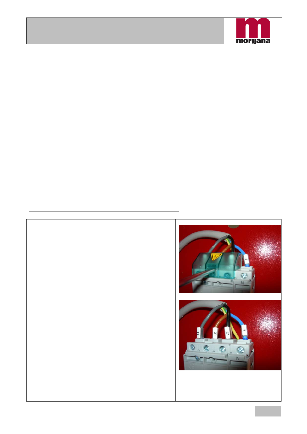
Beforestartingthemachine,youmustverifythecorrectwiring.
1. Verifythatthemachine'smainswitchisinposition0
andthattheplugisnotconnected.
2. RemovetheprotectivecoverasshowninPicture0.1.
3. Inserttheplug.
4. PayattentiontothecablelightbluelabelN,always
refertotheneutral.
5. Verifythecorrectpresenceofvoltagebetweenthe
terminals(Picture.0.2and0.3)asindicated:
a. L1L2(400Vac)
b. L2L3(400Vac)
c. L1L3(400Vac)
d. L1N (230Vac)
e. L2N (230Vac)
f. L3N (230Vac)
6. Iftensionsarenotasindicatedverifythecorrect
positionofneutralonthewallsocket.
Fig.0.1
Fig.0.2

TechnicalSetting
4
7. Ifthevoltagesareasindicated,proceedwith
checkingofthecorrectrotationofthemilling.
Fig.0.3
8. EnterpasswordinthepagedisplayN°61,Picture0.4,
pressbuttonandverifythedirectionofthemilling
rotation(clockwise).
9. Ifthemillingrotationisincorrect:
a. Turnthemainswitchtoposition0
b. Disconnecttheplug.
c. reversethewiresmarkedwiththeletterL
(forexampleL1andL2)
d. Reconnecttheplug.
e. Turnmainswitchtoposition1
f. RepeatoperationsfromStep8.
10. Ifthemillingrotationiscorrect:
a. Turnthemainswitchtoposition0
b. Disconnecttheplug.
c. Restoretheprotectivecoverasshownin
Picture0.1
Fig.0.4

TechnicalSetting
5
Startupconditions
Startingconditionsforcheckingthemachinesetupvalues:
1) Machineonandatcorrecttemperature.
2) Joggerknobsetto0.
3) MillingcuttersettoONposition.
4) Heightadjustmentknobofgluingunitsetto‘0’.
5) Internaljawadjustmentknobofgluingunitsetto‘1’.
6) Gluingpressuresetto‘0’.
7) Heightadjustmentofnippingstationsetto‘0’.
8) Machineinresetcondition.
9) Removetheclampcover.
CheckheightofZero(MZ)
ThemachineiscalibratedinthefactorywithameasureofZerowhichcanrangefrom96to97mm,
thisisnotasignofpoorquality.
AnyorganwillfollowthisMZ(measurezero)withtheappropriatetolerances.
HowtounderstandwhatistheMZ,proceedwiththemeasureofthejoggeranddoaquickcheck
withtheothergroups.

TechnicalSetting
6
1)Settingthejoggerplate
Joggerfeatures:
1) perpendiculartotheclamp
2) paralleltotheclampmovement
±0.1mm.
3) MZ±0.1mmfromtheTopPlate
ofthecursor
4) holdsthesheets
5) BlockMassembly
6) Referenceheight‘X’
1)Perpendicularalignmenttestofthejogger.
Place a 50 x 80 mmsquare on its shorter side
ontothejoggerplate(seeFig.1.1)andcheckfor
perpendicularalignment.
The positioning tolerance allows a thickness of
0.05 mm to pass through but not a 0.1 mm one
(onthe80mmside).
If it does not, adjust the 4 screws underneath.
This check must be done at both ends of the
joggerplate(seeFigs.1.2and1.3).
N.B.Alwaysusethesametestpoints
ontheclamp.
Fig.1.1
Fig.1.2
Fig.1.3
TechnicalSetting
7
2)Parallelismtestofthejogger
Reset the clamp, then position it, completely
opened, on the left side of the jogger and
measure using the depth gauge as shown in Fig.
1.4. Then move it to the right side and measure
withthedepthgaugeasshowninFig.1.5.
Parallelism is reached when the two
measurementsareeitherequal orthedifference
betweenthemisnotbiggerthan±0.1mm.
Ifthedifferencebetweenthevaluesisbiggerthan
±0.1mm,adjustthe4centraladjustingscrews.
After reaching parallelism, check again for
perpendicular alignment as described above in
point 1, as it may have been put out of
calibration.
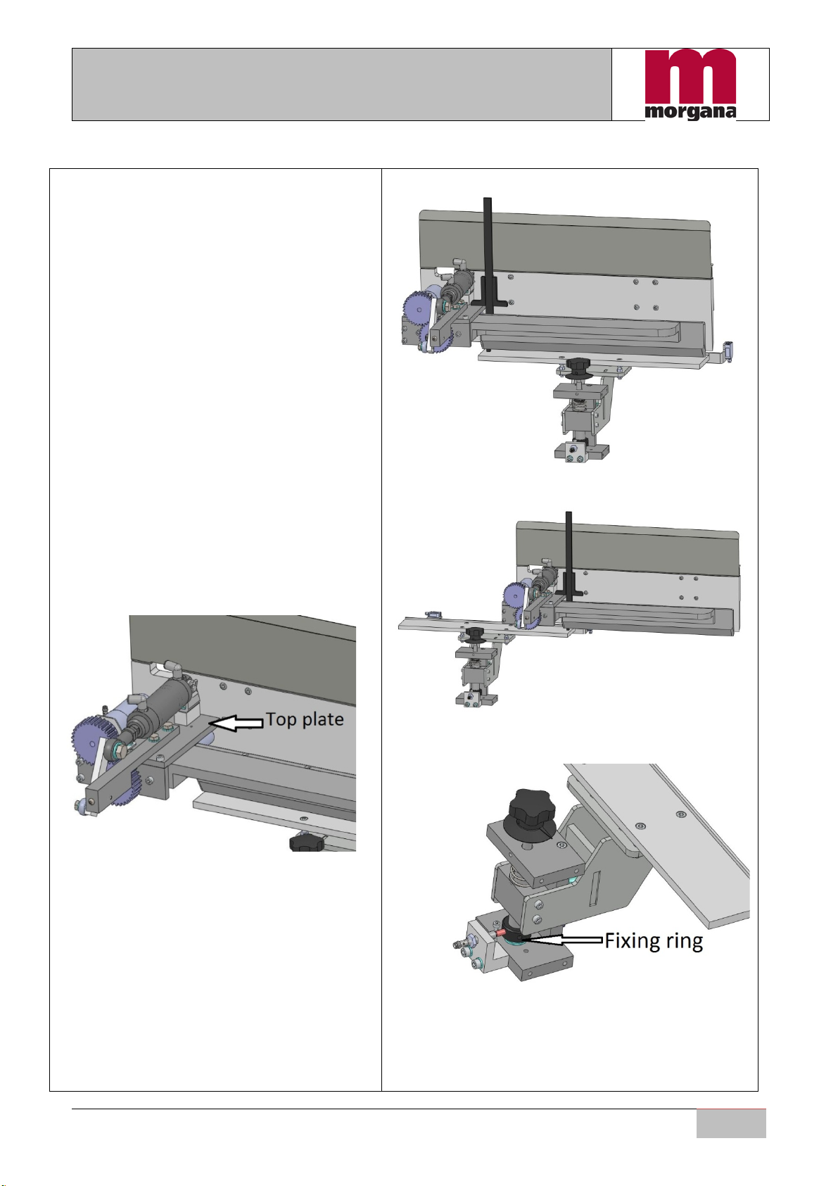
3)HeightcheckfromtheTopPlate
PositionthedepthgaugeasshowninFig.1.4and
measuretheheight.
ItmustbeMZ±0.1mm.
Ifgreaterthan0.1mm,adjustthe‘Fixingring’and
positionitagainsothattherestrainerisincontact
when the distance between clampand jogger is
MZ±0.1mm.
Fig.1.4
Fig.1.5
Fig.1.6
TechnicalSetting
8
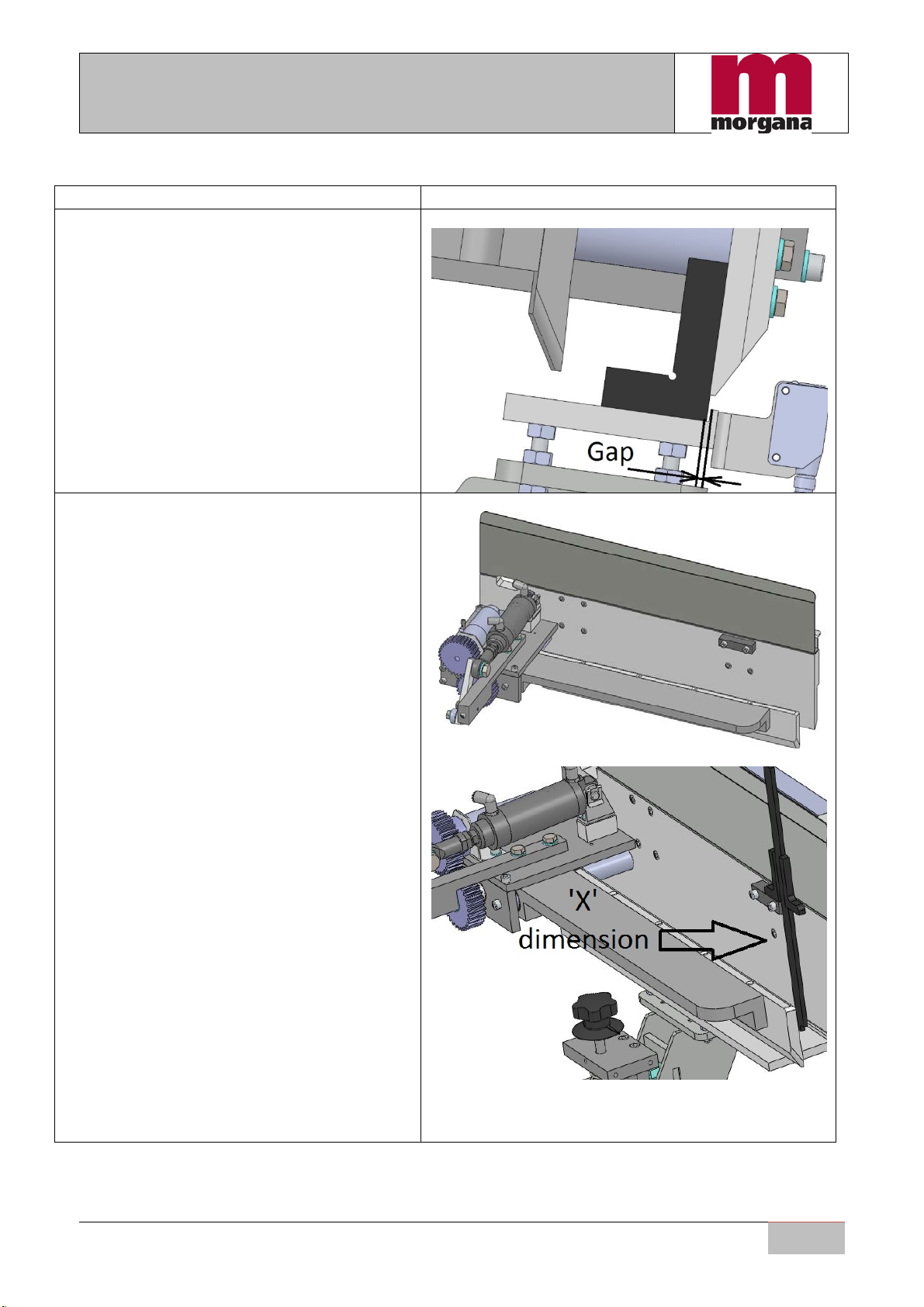
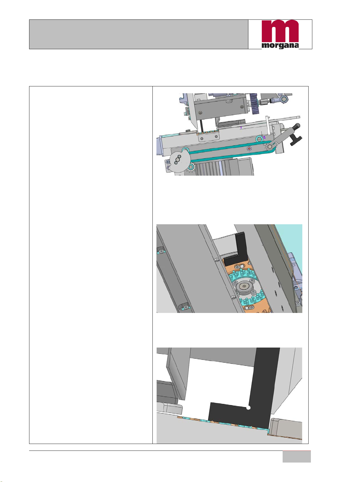
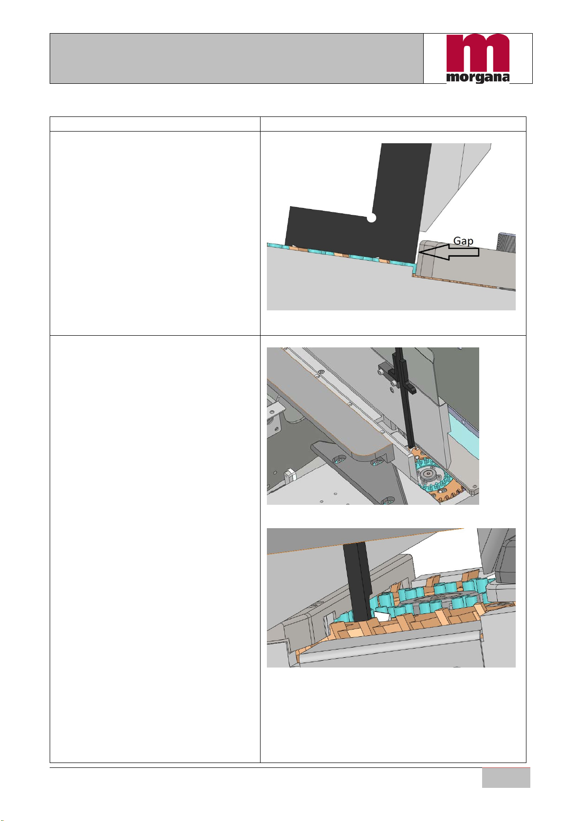
4)Gaptoholdthesheets.
The jogger has a gapthat serves to holdthe
sheetswheninsertedintotheclamp.
This gap must be at about 2.5 ±0.5 mm (GAP)
distance from the edge of the fixed jaw of the
clamp,asshowninFig.1.7.
Fig.1.7
5)AssemblyofBlockM.
After testing and setting up the jogger’s
characteristics,mountthegaugeblockdefinedas
‘BlockM’inFig.1.8.
BlockM serves for testing the other machine
units therefore it becomes the main reference
unit.
6)ReferenceheightX.
Measure the distance between the gauge block
and jogger. The resulting figure will be taken as
thereferenceheight‘X’(Fig.1.9).
Thisheightwillserveasareferencefortheother
units.
Fig.1.8
Fig.1.9
TechnicalSetting
9
2)Settingthespinepreparationunit
Millingdiskfeatures:
1) perpendiculartotheclamp
2) The rear platemust be
paralleltotheclampandata
distance of 0.4 ±0.2 mm
inwardsfromtheclamp.
3) on the left of the milling
cutter disk, the distance
between 'BlockM’ and the
toothmilling disk must be
equaltoX±0.1mm.
4) ontherightsideofthetooth
milling disk, the distance
between 'BlockM’ and the
millingdiskmustbeequalto
(X+0.3)±0.2mm.
A. unitadjustment.
5) the striker plate must be at
0.15mmhorizontallyand1.0
mmvertically from the
millingcutterteeth.
6) Coverfrontfurnituremustbe
more internal than the
movable jaw of 1mm ±
0.5mm.
1)Perpendicularalignmenttestofthe
spinepreparationunit.
Placea50x80mmsquareonitsshorterside
ontothemillingcutterdisk(seeFig.2.2)and
checkforperpendicularalignment.
Positioningtoleranceallowssheets0.05mm
thicktopassthroughbutnot0.1mmones
(onthe80mmside).Ifitdoesnotpass,turn
the4adjustmentscrews,seepoint4A.
Fig.2.1
Fig.2.2
Fig.2.3
TechnicalSetting
10
2)Parallelismtestofthespine
preparationunit.
WhenplacingthesquareasshowninFig.2.4
thegapbetweenthefixedjawandthestriker
plate of the milling cutter must be 0.4±0.2
mm.Thecheckmustbedoneatbothendsof
thestrikerplate.
If the measurements do not correspond,
slightlyloosenthefixingscrews(Fig.2.9)and
move the whole milling cutter unit, then
tightenthescrewsagain.
Fig.2.4
3)Checkofthespinepreparationunit
heightontheleftside.
MeasurethedistancefromBlockMtothe
millingdiskusingthedepthgauge,asinFig.
2.5,makingsurethatyouplacethedepth
gaugeonthetoothasshowninFig.2.6.
On the left side of themilling disk, the
distance between BlockM plane and a tooth
ofthemillingcuttermustbeX±0.1mm.Ifit
is not, adjust the 4 adjustment screws; see
point4A.
Fig.2.5
Fig.2.6
Other manuals for DigiBook 450
1
Table of contents
Other Morgana Binding Machine manuals

Morgana
Morgana DigiBook 200 User manual

Morgana
Morgana KB2000 User manual

Morgana
Morgana AutoCreaser Pro 50 User manual

Morgana
Morgana DigiBook 150r1 User manual

Morgana
Morgana AutoCreaser 50 User manual

Morgana
Morgana DigiBook 300r2 User manual

Morgana
Morgana DigiBook 450 User manual

Morgana
Morgana DigiCreaser User manual


