H2Scan HY-OPTIMA 1730 User manual

HY-OPTIMA™ 1700 Series
ATEX Intrinsically Safe In-line Hydrogen Process Analyzer
OPERATING MANUAL

HY-OPTIMA™ 1700 Series Operating Manual
90000011 R16Page 2 of 41
MISSION STATEMENT
Our Mission
Deliver unsurpassed value and optimize green initiatives with our one of a kind continuous hydrogen-specific
sensing technology worldwide.
Our Value Propositions
Enable end-user customers to efficiently and effectively optimize:
•Electric utility power transformer fleet and other oil-filled assets (Grid)
•Petroleum refinery and other industrial process control
•Facility and equipment safety to minimize downtime
...at a much lower total costs of ownership than the competition.
Our Strategic Objectives
H2scan's technology accepted as the new gold standard in hydrogen sensors.
H2scan's business recognized for innovation and ingenuity, high quality products and systems, application -
specific solutions, and exceptional customer service and satisfaction.
H2scan's success results from teamwork, strategic partnerships and market leadership leading to sales growth
and improved profitability.
Manual release date: 09/12/2017
1700 series firmware revision at date of manual release: 1.80i (sensor board), 1.25i (display board)

HY-OPTIMA™ 1700 Series Operating Manual
90000011 R16Page 3 of 41
Chapter 1: Model Specifications and Certifications
1.1 Description.................................................................................................................... 6
1.2 Models.......................................................................................................................... 6
1.2.1 Model 1720 .............................................................................................................6
1.2.2 Model 1730 .............................................................................................................7
1.2.3 Model 1740 .............................................................................................................7
1.3 Specifications................................................................................................................ 8
1.3.1 Performance Specifications.....................................................................................8
1.3.2 Operating Specifications .........................................................................................8
1.4 Analyzer ATEX Rating.................................................................................................. 9
1.5 Dimensions................................................................................................................. 10
Chapter 2: Installation
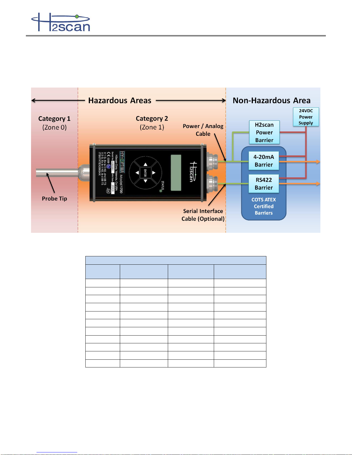
2.1 Associated Equipment................................................................................................ 11
2.2 Analyzer Mounting...................................................................................................... 11
2.3 Power and Analog Connector..................................................................................... 12
2.4 Serial Connector......................................................................................................... 12
2.5 Startup........................................................................................................................ 13
2.5.1 Models 1710, 1730, 1740......................................................................................13
2.5.2 Model 1720 ...........................................................................................................13
2.6 Shutdown.................................................................................................................... 13
Chapter 3: Operation and Configuration
3.1 Optimum Analyzer Performance................................................................................. 14
3.1.1 Effect of Pressure..................................................................................................14
3.1.2 Calibration Gas Bottle Accuracy............................................................................14
3.2 Analog Output............................................................................................................. 14
3.2.1 Calibrate the Analog Output..................................................................................15
3.3 Serial Communication................................................................................................. 15
3.3.1 Serial Command Summary ...................................................................................15
3.3.2 A Command (LED Set Points)...............................................................................16
3.3.3 D Commands (Display Product Information).........................................................16
3.3.4 G Command (Go, Stream Data)............................................................................17
3.3.5 H Command (Modify H2 Reporting Range)...........................................................17
3.3.6 I Command (Modify Analog Output)......................................................................17
3.3.7 X Command (Clear Field Cal) ...............................................................................18
3.3.8 F Command (Field Cal).........................................................................................18
3.4 Display........................................................................................................................ 18
3.4.1 Keypad..................................................................................................................18
3.4.2 Configuration Menu...............................................................................................19
3.4.3 Display Menus.......................................................................................................20
Chapter 4: Field Calibration
4.1 Calibration Interval...................................................................................................... 25
4.2 Calibration Gases....................................................................................................... 25
4.2.1 Background Gases................................................................................................25
4.3 Calibration Procedure................................................................................................. 26
4.3.1 Procedure Using the Keypad.................................................................................26

HY-OPTIMA™ 1700 Series Operating Manual
90000011 R16Page 4 of 41
4.3.2 Procedure Using the Serial Interface.....................................................................29
4.3.3 Clear Field Calibration (Restore Factory Calibration)............................................29
Chapter 5: Supplemental Information and Troubleshooting
5.1 Storage....................................................................................................................... 30
5.1.1 Storage Oxidation & Offsets..................................................................................30
5.1.2 Expected Oxidation Time and Recovery Time ......................................................30
5.1.3 Conditioning to Remove an Offset.........................................................................30
5.1.4 Avoiding a Storage Oxidation Offset .....................................................................31
5.2 Sensor Behavior......................................................................................................... 31
5.2.1 H2 Measurement...................................................................................................31
5.2.1.1 Inert Backgrounds .......................................................................................... 31
5.2.2 H2 Detection..........................................................................................................31
5.2.3 Diurnal Effect.........................................................................................................31
5.3 General Troubleshooting ............................................................................................ 32
5.4 Command Terminal Messages................................................................................... 32
5.5 Serial Communication Troubleshooting...................................................................... 33
5.5.1 Connections ..........................................................................................................34
5.5.2 COM Port Number.................................................................................................34
5.5.3 USB Adaptor Device Driver:..................................................................................34
5.5.4 Rebooting..............................................................................................................34
5.5.5 Terminal Program..................................................................................................34
5.5.6 Analyzer Command Line.......................................................................................35
5.6 Analog Output Troubleshooting.................................................................................. 35
5.6.1 Verify the hydrogen values....................................................................................35
5.6.2 Verify the H2 range ...............................................................................................35
5.6.3 Verify the Analog Output .......................................................................................36
5.6.4 Verify the SCADA analog input .............................................................................36
5.6.5 Calibrate the Analog Output..................................................................................36
Appendix A: Control Drawings............................................................................................ 37
A.1 Serial Barrier Switch Settings for RS232 Connection to PC ......................................... 40
Appendix B: Spare Parts...................................................................................................... 40
Appendix C: Foxterm Setup................................................................................................. 41

HY-OPTIMA™ 1700 Series Operating Manual
90000011 R16Page 5 of 41
IMPORTANT NOTICES
LIMITED WARRANTY
H2scan Limited Warranty: Each hydrogen instrument (“Product”) will conform, as to all substantial operational features, to the Product
specifications set forth in this Manual and will be free of defects which substantially affect such Product’s performance for twelve (12) months
from the ship date for such Product.
Must Provide Notice of Defect: If you believe a Product that you believe is defective, you must notify H2scan in writing, within ten (10) days
of receipt of such Product, of your claim regarding any such defect.
Return Product to H2scan for Repair, Replacement or Credit:If the Product is found defective by H2scan, H2scan’s sole obligation under
this warranty is to either (i) repair the Product, (ii) replace the Product, or (iii) issue a credit for the purchase price for such Product, the
particular remedy to be determined by H2scan on a case-by-case basis.
Voided Warranty: H2scan’s 12 Month Limited Warranty is void for any of the following:
The unit is opened and the manufacturing seal is broken
Unauthorized repair work performed at the customer’s location or carried out by anyone other than H2scan’s factory trained technicians
Equipment or parts that have been tampered with, misused, neglected, mishandled, improperly adjusted, or modified in any way without the
written consent of H2scan.
Equipment or parts that have been damaged due to shipping, misuse, accidents, mishandling, neglect, or problems with electrical power
sources.
Repair work performed during the warranty period does not prolong the warranty period past the original period.
System operation in incorrect or inappropriate environments.
Usage that is not in accordance with system guidelines or an operator’s failure to follow manual instructions.
LIMITATION OF WARRANTY: THE ABOVE IS A LIMITED WARRANTY AS IT IS THE ONLY WARRANTY MADE BY H2SCAN. H2SCAN
MAKES NO OTHER WARRANTY EXPRESS OR IMPLIED AND EXPRESSLY EXCLUDES ALL WARRANTIES OF MERCHANTABILITY
AND FITNESS FOR A PARTICULAR PURPOSE. YOUR SOLE REMEDY HEREUNDER IS REPAIR OR REPLACEMENT OF THE
PRODUCT OR A CREDIT FOR THE PURCHASE PRICE FOR SUCH PRODUCT, THE PARTICULAR REMEDY TO BE DETERMINED BY
H2SCAN ON A CASE-BY-CASE BASIS. H2SCAN SHALL HAVE NO LIABILITY WITH RESPECT TO ITS OBLIGATIONS UNDER THIS
AGREEMENT FOR CONSEQUENTIAL, EXEMPLARY, OR INCIDENTAL DAMAGES EVEN IF IT HAS BEEN ADVISED OF THE
POSSIBILITY OF SUCH DAMAGES. THE STATED EXPRESS WARRANTY IS IN LIEU OF ALL LIABILITIES OR OBLIGATIONS OF
H2SCAN FOR DAMAGES ARISING OUT OF OR IN CONNECTION WITH THE DELIVERY, USE OR PERFORMANCE OF THE
PRODUCTS.
Read and understand this operating manual before installing or using the unit.
Only use cables from H2scan with this unit.
If this equipment is used in a manner not specified by H2scan, the protection provided by this equipment may be impaired.
Hydrogen is flammable at 4% in air. Take indications seriously and be prepared to take action. In the event of detection of 4% or higher
of a hydrogen gas concentration there is a high probability of a hazard to safety. Inform local emergency response personnel
immediately.
Do not apply power to the analyzer if the sensing element is exposed to air. This could severely affect accuracy and stability.
LIMITATION OF LIABILITY - SELLER SHALL UNDER NO CIRCUMSTANCES BE LIABLE FOR ANY INCIDENTAL, CONSEQUENTIAL,
SPECIAL, PUNITIVE, OR OTHER DAMAGES, INCLUDING, BUT NOT LIMITED TO, LOSS OF BUSINESS OR PROFIT, PROMOTIONAL OR
MANUFACTURING EXPENSES, INJURY TO REPUTATION, OR LOSS OF CUSTOMER, BASED ON ANY ALLEGED NEGLIGENCE, BREACH
OF WARRANTY, STRICT LIABILITY, BREACH OF CONTRACT, OR ANY OTHER LEGAL THEORY ARISING OUT OF THE USE, MISUSE,
PURCHASE, SALE OR POSSESSION OF ITS GOODS OR ITS PERFORMANCE OF THIS CONTRACT TO THE EXTENT THAT SUCH
LIABILITY EXTENDS SELLER’S OBLIGATIONS BEYOND THE PRICE PAID BY BUYER TO SELLER FOR THE ITEM ON WHICH SUCH CLAIM
IS BASED. SELLER ADVISES BUYER TO PERFORM ACCEPTABLE TESTS ON ALL HARDWARE PRIOR TO DEPLOYMENT AND TO
PERFORM MAINTENANCE AS DESCRIBED IN THE SELLER’S INSTRUCTION GUIDE. UNDER NO CIRCUMSTANCES SHALL THE
EQUIPMENT PROVIDED HEREUNDER BE USED IN A MANNER WHERE IT IS THE SOLE PROTECTIVE SYSTEM FOR FACILITIES,
EQUIPMENT AND PERSONNEL SAFETY; THE EQUIPMENT IS INTENDED FOR USE IN CONJUNCTION WITH OTHER APPROPRIATE
PROTECTIVE SYSTEMS.

HY-OPTIMA™ 1700 Series Operating Manual
90000011 R16Page 6 of 41
Chapter 1: Model Specifications and Certifications
1.1 Description
The HY-OPTIMA™ 1700 Series, Intrinsically Safe In-line Hydrogen Process Analyzer is designed to detect and/or
measure hydrogen using a solid-state, non-consumable sensor that is configured to operate in process gas
streams. The H2scan thin film technology provides a direct hydrogen measurement that is not cross sensitive to
other gases. The hydrogen specific solid-state sensing element is designed for ease of use, interface flexibility
and true process control. The analyzer contains all the circuitry necessary to operate the sensor and present
calibrated hydrogen readings to an analog current output and an RS422 digital output. The analyzer is ideal for
hydrogen production and petrochemical applications where real-time measurements can enhance process plant
efficiencies, diagnostics, and maintenance management.
1.2 Models
The HY-OPTIMATM 1700 Series product family includes sensor types that are designed for specific hydrogen
ranges, corrosive gas tolerances and operation when no hydrogen is present. See the guide below for more
details.
MODEL
Hydrogen
Range
Hydrogen
MUST be
present
CO
Limit
H2S
Limit
Calibration
Background
Gas
Max
Pressure
Min
Max
1730
0.5%
100%
Yes
<100 ppm
<1000 ppm
N2
2 atm
1740
0.5%
100%
Yes
20%
3%
N2
2 atm
1720
0.4%
5%
No1
0
0
O2, N2
2 atm
Notes:
1. 1720 models operated in background streams in which H2 is not typically present and may be operated in
an Air, O2, or N2 background.
1.2.1 Model 1720
The HY-OPTIMATM 1720 Process Hydrogen Analyzer has been specifically manufactured to operate in an air or
inert background.
•Operation in background streams in which H2 is not typically present
•Calibration Background Gas: Air or Inert
•Hydrogen Sensitivity Range:
o0.4% to 5% hydrogen by volume at 1.0 atm
o10% to 125% hydrogen lower flammability limit
Note:
Please disregard all warnings and statements to avoid operation in air or oxygen background; these warnings and
statements do not apply to the HY-OPTIMATM 1720 Process Hydrogen Analyzers which have been manufactured
for implementation in background gas streams with air.
HY-OPTIMA™ 1720 Process Hydrogen Analyzers operating in air do not require the conditioning procedure.
H2scan recommends the hydrogen gas concentrations for both the Field Verification and Field Calibration gases
to be 1% and 2% hydrogen in a balance of air.

HY-OPTIMA™ 1700 Series Operating Manual
90000011 R16Page 7 of 41
1.2.2 Model 1730
The HY-OPTIMATM 1730 Process Hydrogen Analyzer has been specifically manufactured to operate in full range
(0.5% to 100%) hydrogen conditions with the following enhanced tolerances to CO and H2S in process gas
streams:
•CO tolerance: 100 ppm
•H2S tolerance: 1000 ppm
1.2.3 Model 1740
The HY-OPTIMATM 1740 Process Hydrogen Analyzer has been specifically manufactured to operate in full range
hydrogen conditions with the following enhanced tolerances to CO and H2S in process gas streams:
•CO tolerance: 20% by volume
•H2S tolerance: 3% by volume

HY-OPTIMA™ 1700 Series Operating Manual
90000011 R16Page 8 of 41
1.3 Specifications
1.3.1 Performance Specifications
MODEL
Hydrogen
Range
Hydrogen
MUST be
present
CO
Limit
H2S
Limit
T90
Response
Time (sec)
Accuracy
Drift/Week
Repeatability
Linearity
Min
Max
Min to
10% H2
10 to
Max% H2
Min to
10% H2
10 to
Max% H2
Min to
10% H2
10 to
Max% H2
Min to
10% H2
10 to
Max% H2
1730
0.5%
100%
Yes
<100 ppm
<1000 ppm
< 60
0.3%
1.0%
0.2%
0.4%
0.2%
0.4%
0.2%
0.4%
1740
0.5%
100%
Yes
20%
3%
< 90
0.3%
1.0%
0.2%
0.4%
0.2%
0.4%
0.2%
0.4%
1720
0.4%
5%
No1
0
0
< 60
0.3%
N/A
0.3%
N/A
0.3%
N/A
0.3%
N/A
Note: Sensor performance specifications are absolute and assume a dry process stream, an ambient temperature of 25°C, pressure compensation, and are in
addition to any errors in the calibration gases used. The accuracy is specified for the serial port and digital display output only.
1. 1720 models operated in background streams in which H2 is not typically present and may be operated in an Air, O2, or N2 background.
1.3.2 Operating Specifications
Sample Gas Flow Rate
0.1 to 10 slpm (1 slpm is recommended)
Temperature
Gas Stream:
Sensor Ambient Temperature:
Storage:
+10°C to +60°C
-20°C to +40°C
-40°C to +50°C
Analyzer Input Voltage
Range:
Intrinsically Safe:
5 VDC to 28 VDC
10 VDC, 6 W
Power Barrier Input
Voltage
Range:
Nominal:
20 VDC to 28 VDC
24 VDC
Analog Output
Isolated, Loop Powered, 4-20 mA
Serial Communication
RS422
19.2 kbps, No Parity, 8 Bit Data, 1 Stop Bit, No Flow Control (preferred) or Xon/Xoff
Certifications
0359
ITS07ATEX25634X
II 1 G, Ex ia II H2, d+d IIB T3 Ga
II 2 G, Ex ib II H2, ib d IIB T3 Gb
Analyzer Weight
1 lb

HY-OPTIMA™ 1700 Series Operating Manual
90000011 R16Page 9 of 41
1.4 Analyzer ATEX Rating
The HY-OPTIMA™ 1700 Series Analyzers are certified with a dual zone rating.
Electronics Assembly is Zone 1
Probe Tip is Zone 0
Figure 1: Hazardous Area Installation and Attachment
Table 1: Hazardous Area Equipment Ratings
Input and Output Parameters
Parameter
J1 Pins 2&3
(Power Supply)
J1 Pins 4&5
(4-20 mA loop)
J2 Pins 1&2, 3&4
(RS422 Rx&Tx)
Ui
11.5 V
26.7 V
3.7 V
li
3.27 A
91 mA
2.25 mA
Pi
9.41 W
611 mW
206 mW
Ci
0
68.2 nF
0
Li
0
0
0
Uo
n/a
n/a
5.9 V
Io
n/a
n/a
238 mA
Po
n/a
n/a
350 mW
Co
n/a
n/a
1000 uF
Lo
n/a
n/a
2.5 mH
Lo/Ro
n/a
n/a
404 uH/Ω

HY-OPTIMA™ 1700 Series Operating Manual
90000011 R16Page 10 of 41
1.5 Dimensions
(Units in inches)

HY-OPTIMA™ 1700 Series Operating Manual
90000011 R16Page 11 of 41
Chapter 2: Installation
WARNING: H2scan’s HY-OPTIMA™ 1730 Intrinsically Safe In-line Hydrogen Process Analyzers (ATEX) are
calibrated in a hydrogen/nitrogen (H2/N2) background and should NEVER be operated in an air or oxygen
background.
The analyzer can be exposed to oxygen for short periods of time without adverse effects if the analyzer is turned
off. If the analyzer is operated in oxygen or stored in air for longer than a week, the hydrogen readings may be
high due to oxygen adsorption on the sensor. Hydrogen exposure will then cause the readings to drift lower as
adsorbed oxygen is slowly removed and the unit recovers to normal steady behavior.
If this drift behavior is observed, the sensor should be conditioned by operating in a hydrogen concentration
exceeding 5% until the readings are stable. The required hydrogen conditioning may vary from several hours to
several days depending on the level of oxygen exposure. Higher hydrogen concentrations used during
conditioning may accelerate the process. Once stable, the analyzer should be checked for accuracy and
calibrated if needed. See 5.1.3 Conditioning to Remove an Offset for more information.
2.1 Associated Equipment
WARNING: If the analyzer is installed in a classified location then it is the responsibility of the user and
installer to make connections to related equipment in a manner consistent with the location classification.
Only H2scan specified cables should be used with this Analyzer. The maximum length for intrinsically safe
operation of both the Power/Analog Cable and the Serial Interface Cable is 10 meters. Refer to Appendix A:
Control Drawings.
When operated in a hazardous area, the HY-OPTIMA™ 1730 Analyzer must be connected to appropriately
certified barriers located in a non-hazardous area using H2scan specified cables. The following barriers are
approved for use with this device for an Intrinsically Safe implementation:
Intrinsically Safe Power Barrier: H2scan’s custom designed barrier supplies 10VDC, 6W power to the sensor.
Intrinsically Safe Analog Output Barrier (4 mA to 20 mA): GM International D1054S or equivalent, One
Channel Repeater Power Supply and Trip Amplifiers. Refer to the D1054S Operating Manual for installation and
configuration of this barrier.
Intrinsically Safe Serial Interface Barrier (RS422): GM International D1061S or equivalent, RS422 / RS485
Fieldbus Isolating Repeater. Refer to the D1061S Operating Manual for installation and configuration of this
barrier. This barrier also requires a null modem cable for communication between PC and Barrier.
2.2 Analyzer Mounting
The analyzer has been mounted in the system vertically with the sensor tube pointing downward to prevent liquids
or potentially condensing gases from damaging the sensor.
Mounting is achieved by securing the sensor tube into the supplied fitting directly into the process stream.
Optional mounting brackets which attach to the instrument housing have been included to secure the analyzer to
the backplane.
The length of tube within 1.25 inches from the end plate of the analyzer is called the Ferrule Region and has a
thick wall. Past this, the tube wall thickness is too thin to support a cinched fitting.
H2Scan offers a variety of fittings to mate the unit to a process stream. The following lists our standard fitting
selections. Others are available upon request.
•½" MNPT thread
•½" FNPT thread
•-8 SAE/MS thread

HY-OPTIMA™ 1700 Series Operating Manual
90000011 R16Page 12 of 41
Warning: Do not cinch down or tighten ferrules outside of the ferrule region of the tube or risk
permanently damaging the tube and sensor assembly within.
Warning: If the unit is installed in a classified location then it is the responsibility of the user and installer
to make connections to related equipment in a manner consistent with the location classification.
2.3 Power and Analog Connector
Supplied Cable: 4m (13 ft) standard
Wire Color
Description
Red
+10 VDC
Black
10 VDC Return
White
+4 mA to 20 mA
Blue
4 mA to 20 mA Return
Bare
Chassis Ground
2.4 Serial Connector
Supplied Cable: 4m (13 ft) standard
Wire Color
Description
Black
+TxD RS422
Blue
-TxD RS422
White
+RxD RS422
Brown
-RxD RS422

HY-OPTIMA™ 1700 Series Operating Manual
90000011 R16Page 13 of 41
2.5 Startup
2.5.1 Models 1710, 1730, 1740
If the analyzer is being turned on from an off position, power on the analyzer before flowing gas across the
sensor. The sequence of steps which are to be followed is:
1. Power on the analyzer and wait for the 5 minute warmup routine to complete.
2. Apply the low span calibration gas to the analyzer and wait for the reading to stabilize (typically 2
hours on first startup). See Section 4.2 Calibration Gases for choosing the low and high span gas
concentrations. Do not apply greater than 10% H2/N2 to the Model 1710.
3. Perform a Field Calibration (see Chapter 4: Field Calibration).
The analyzer can be exposed to oxygen for short periods of time without adverse effects if it is turned off. If it is
stored in air for longer than a week, the analyzer may read higher than the true hydrogen concentration due to
oxygen absorption on the sensor. Steady hydrogen exposure will slowly remove this absorbed oxygen and cause
the analyzer reading to continually drift downward until it reaches the true hydrogen concentration.
If this drift behavior is observed refer to Section 5.1.3 Conditioning to Remove an Offset for instructions and more
information.
2.5.2 Model 1720
If the analyzer is being turned on from an off position, power on the analyzer before flowing gas across the
sensor. The sequence of steps which are to be followed is:
1. Power on the analyzer and wait for the 5 minute warmup routine to complete.
2. Apply air for 30 minutes.
3. Perform a Field Calibration (see Chapter 4: Field Calibration).
The analyzer is designed to be exposed to an air or inert background gas where hydrogen is normally absent. For
optimal performance keep any hydrogen exposure to the sensor to less than one hour. If the hydrogen exposure
exceeds this time, the sensor may need to be reconditioned by leaving it powered on in air for at least 24 hours.
2.6 Shutdown
1. Purge the system using gas with a hydrogen concentration of less than 5% H2 or with 100% N2 for 5
minutes.
2. Turn off all gas flow to the analyzer.
3. Power off the analyzer.

HY-OPTIMA™ 1700 Series Operating Manual
90000011 R16Page 14 of 41
Chapter 3: Operation and Configuration
3.1 Optimum Analyzer Performance
To maximize the performance of the analyzer:
•Verify that all electrical connections are made as recommended. Switching the polarity can cause damage to
the analyzer.
•Verify the process gas stream is properly regulated with a stable pressure and flow between 0.1 and 10 slpm
(1.0 slpm is recommended).
•After installation complete the conditioning steps described in the Section 2.5 Startup and perform a Field
Calibration (Chapter 4: Field Calibration). Use two calibration gases for the Field Calibration for optimal
results.
A back pressure controller can be installed to improve performance and stability.
3.1.1 Effect of Pressure
The analyzer is hydrogen specific and sensitive to only the hydrogen partial pressure in the gas stream. Since
changes in total gas pressure will affect the hydrogen partial pressure, they will also affect the analyzer readings.
At 1.0 atm, a 50% H2/N2 mixture will be reported as 50% by the analyzer. At 1.1 atm the reading will increase to
55% and 2.0 atm will result in a reading of 100%. The analyzer is capable of measuring multiple atmospheres of
hydrogen, and readings above 100% H2 are interpreted as hydrogen pressures above 1.0 atm. For example, a
reading of 150% H2 means 1.5 times the hydrogen pressure of a 100% H2 concentration at 1.0 atm. The
analyzers are factory calibrated at 1.0 atm. Performing the Field Calibration at the operating pressure will correct
the hydrogen reading for static pressures. For example, if the local atmospheric pressure is 0.97 atm, doing a
Field Calibration will correct for this assuming the pressure remains static. Installing a back pressure controller
can increase performance and stability of the analyzer.
3.1.2 Calibration Gas Bottle Accuracy
The inaccuracy of the gas bottle concentration will directly affect the measured accuracy by the analyzer. During
factory calibration, the analyzers are calibrated with high accuracy gases (as high as +/- 0.02% accurate). It is
strongly recommended that the user perform calibration with similar high accuracy gases to maintain the accuracy
specified in the manual.
3.2 Analog Output
The analog output is derived from the final hydrogen value as shown on the serial display and is scaled to the
hydrogen and current ranges desired. All of this is initially set to factory defaults as shown in the table below or
per customer specifications at the time of order. They can also be changed with the “H” and “I” commands. If the
distance between the high and low H2 range is reduced then more current resolution is obtained in the valid H2
region. This may be desirable if the system will only be operating in a specific concentration region, like 90-100%
H2 concentration for example. The value of the low and high H2 current should be set according to the
specifications of the measuring equipment. By default they are 4 mA and 20 mA, respectively.
Variable
Label in Device
Default Value and Units
LowH2Current
4 mA
HighH2Current
20 mA
LowH2Range
0% H2
HighH2Range
100% H2
Use the following equation to calculate hydrogen from the analog output:

HY-OPTIMA™ 1700 Series Operating Manual
90000011 R16Page 15 of 41
Where is the concentration of hydrogen measured as a percent, and are the high and low H2
currents measured in mA, and and are the upper and lower hydrogen concentration limits as a percent.
These values can be displayed using the “D 1”command over the serial port.
3.2.1 Calibrate the Analog Output
If the range is correct and the analog output is inaccurate, it may require calibration.
Use the “ci” command.
3.3 Serial Communication
The user can monitor and log the output and interface with the analyzer to perform calibration or adjust user
settings via the serial communication connector. The serial communication is accomplished via the serial
interface.
Serial Communications Software –Any serial port two-way communications software such as terminal emulators
(H2scan uses Foxterm) and purpose-built software (using LabView, Visual Basic, C++, etc.) can be used to
establish serial communication with the analyzer. See Appendix C: Foxterm Setup for instructions on setting up a
serial connection.
3.3.1 Serial Command Summary
WARNING: If commands are sent over the serial port the display on the LCD will be unpredictable. To
restore proper LCD operation, cycle the power.
Two communication modes are available:
Keystroke –This is the default mode which shows a continuous stream of output data until an ESC key is
pressed. Then the H2scan prompt is displayed for the user to enter a command. After the command is finished
the stream of output data continues.
Prompted –This mode is entered by executing =H2scan command at H2scan prompt. The analyzer continues
with the H2scan prompt after completing each command. Enter the =0 command to end this mode and continue
the stream of output data.
Keystroke Commands While Data Streams
Keystroke
Description
ESC
Stops continuous display to enter a password or command. If in level zero, the continuous
display will resume after executing one command.
Sp (spacebar)
Pressing the Space key while the serial output is active will display a label line showing the
heading for each column of data.
A
Average readings
C
Clear peak hydrogen value

HY-OPTIMA™ 1700 Series Operating Manual
90000011 R16Page 16 of 41
Prompted Commands @ H2Scan prompt
Command
Description
=<password>
Enter the password to change security level. A null or invalid password returns to level 0.
Level 0 password = “0”
Level 1 password = “h2scan”
A
Modify the alarm set points (Status Indicator LED)
D
Display Product Information
G
Go, resume analyzer operation
H
Modify the hydrogen reporting range
I
Modify the DAC current output range
L
Print current hydrogen reading and pause
P
Select gas pressure in atmospheres (recommended to remain at 1.0 atm)
S
Stop the sensor, turn off heater, set DAC outputs to zero, stop serial data stream
X
Clear field calibration data (returns to last factory calibration data)
F
Perform Field Calibration
3.3.2 A Command (LED Set Points)
The A command is used to modify the alert and alarm set points that control the Status Indicator LED. In this
example Alert is changed to 1% and Alarm is changed to 4%.
One method is prompted:
H2scan: a
Current Alert=101.00000%, Alarm=102.00000%
Enter new Alert value: 1
Enter new Alarm value: 4
New Alert=1.00000%, Alarm=2.00000%
Save these values (Y/N)? y
...Wait...SAVED –Done
Another method is entering the settings directly on the command line. The format is: A <R1 value> <R2 value>:
H2scan: A14
New Alert=1.00000%, Alarm=4.00000%
Save these values (Y/N)? y
...Wait...SAVED - Done
3.3.3 D Commands (Display Product Information)
Display Product Information. Enter page number 0-6 or A for all pages, default (no value) is page 0.
0 –Product information
1 –User configuration
Example:
H2scan: d0
H2scan hydrogen sensor
Model Number: 1730
Serial Number: A000001
Sensor Board Firmware Rev: 1.71i
Display Board Firmware Rev: 1.25i
Table Version: 1.25

HY-OPTIMA™ 1700 Series Operating Manual
90000011 R16Page 17 of 41
Latest Calibration
Factory: 00/00/0000
Field: 00/00/0000
3.3.4 G Command (Go, Stream Data)
The G command is used to resume analyzer operation and specify the arrangement of the data in columns.
These columns are:
Header
Description
TimeStamp
The time in quarter seconds since power on.
PcbTemp
The internal electronics temperature
SnsrTemp
The sensor temperature
ResAdc
The raw hydrogen sensor measurement in ADC counts
AdjRes
The adjusted sensor measurement: these adjustments include compensation for
variations in sensor temperature, sensor electronics, and other parameters
ZRes
Sensor reference value
%H2
The final hydrogen measurement
%H2_Pk
The peak hydrogen measurement
%H2_Res
The hydrogen resistor measurement
Messages
Some messages are displayed in this column
Average
Average indicates that several samples are being averaged
To change display format press ESC followed by G <fmt> <opt>; where <fmt> <opt> is a pair of two digit
hexadecimal numbers. Some common formats are listed below:
Command
Columns
G
Use default
G 02 00
%H2
G 02 06
%H2 Messages
G 03 06
%H2 %H2_Pk Messages
G 07 06
ResAdc AdjRes ZRes %H2_Res %H2 %H2_Pk Messages
G 82 06
TimeStamp %H2 Messages
G B7 06
TimeStamp PcbTemp SnsrTemp ResAdc AdjRes ZRes %H2_Res %H2
%H2_Pk Messages
G FF 06
Display All Columns
3.3.5 H Command (Modify H2 Reporting Range)
Modify the hydrogen reporting range.
H2scan: h
Hydrogen reporting range 0.0000-5.0000% H2
Enter new H2 low range: 1
Enter new H2 high range: 25
New Hydrogen reporting range 1 - 25% H2
Save these values (Y/N)? y
...Wait...SAVED - Done
3.3.6 I Command (Modify Analog Output)
Modify the Isolated DAC output range.
H2scan: i

HY-OPTIMA™ 1700 Series Operating Manual
90000011 R16Page 18 of 41
DAC range is 4.0mA to 20.0mA, error output is 2.0mA, not ready output is 3.0mA
Enter new low H2 output current: 4
Enter new high H2 output current: 20
Enter new error output current: 3
Enter new not ready output current: 2
New DAC range is 4.0mA to 20.0mA, error output is 3.0mA, not ready output is 2.0mA
Save these values (Y/N)? y
...Wait...SAVED –Done
3.3.7 X Command (Clear Field Cal)
Clear field calibration data (returns to last factory calibration setting).
H2scan: x
Clear field calibration values (Y/N)? y
3.3.8 F Command (Field Cal)
Perform a field Calibration. See Chapter 4: Field Calibration more details.
3.4 Display
The upper row of the LCD indicates a numerical value for the percent hydrogen concentration or peak hydrogen
value. The lower row of the LCD is used to display the hydrogen meter, a logarithmic bar graph ranging from
0.001% (10 ppm) to 100% hydrogen by volume. An open box on the bar indicates the last peak value obtained
and filled boxes indicate current value. The following figure describes how to interpret the hydrogen meter:
3.4.1 Keypad
A 5 button keypad is used to alter the LCD, change settings, run field calibration, and initiate special functions
from the Configuration Menu:
Pressing ▲ (up arrow button) displays the peak hydrogen reading.
Pressing ▼ (down arrow button) displays the current percent hydrogen concentration.
Pressing ► (right arrow button) clears the peak hydrogen value.
Pressing and holding the ENTER button invokes the Configuration Menu.
Pressing ▼ (down arrow button) scrolls down through function menus or scroll down through a numerical range.
Pressing ▲ (up arrow button) scrolls up through function menus or scroll up through a numerical range.
Pressing the ENTER button or ► (right arrow button) selects the function.
Pressing ◄ (left arrow button) backs out of menus.
> 0.002
> 0.005
> 0.010
> 0.022
> 0.046
> 0.100
> 0.220
> 0.460
> 1.000
> 2.200
> 4.600
> 10.00
> 22.00
> 46.00
> 100.0
> 0.001
Hydrogen = 4.67%

HY-OPTIMA™ 1700 Series Operating Manual
90000011 R16Page 19 of 41
3.4.2 Configuration Menu
The following functions will be found in the Configuration Menu:
Information Disp –model information
Firmware Rev –firmware revisions
Serial Number –model serial number
Factory Calibration Date –date of the last factory calibration
Set Alert/Alarm –Define hydrogen level that will trigger the alert and alarm signals.
Alert Level –the level of hydrogen that will cause the LED to turn amber
Alarm Level –the level of hydrogen that will cause the LED to turn red
Set H2 Range –the hydrogen sensitivity range (standard factory setting: 0% to 100% hydrogen by volume)
Low H2 Range –lowest level of hydrogen (standard factory setting: 0% hydrogen by volume) to
correspond with the low range IDAC setting
High H2 Range –highest level of hydrogen (standard factory setting: 100% hydrogen by volume) to
correspond with the highest IDAC setting
Configure IDAC –analog output range
Low Range –low level analog output corresponding to the lowest hydrogen range
High Range –high level analog output corresponding to highest hydrogen range
Error –analog output indicating an error
Not Ready –analog output indicating the POST is running
Exit –exit Configuration Menu to standard display output setting

HY-OPTIMA™ 1700 Series Operating Manual
90000011 R16Page 20 of 41
See Hydrogen Menu
Hydrogen = 0%
H
Information Disp
Set Alert/Alarm
Set H2 Range
Configure IDAC
Field Calibrate
0/0/00
See Info Display Menu
H
See Alert Menu
H
See H2 Range Menu
H
See Configure IDAC Menu
H
See Field Calibrate Menu
H
Exiting Menu
Main Menu
H2Scan
Hydrogen Sensor
Warmup_XX
3.4.3 Display Menus
This manual suits for next models
2
Table of contents
Other H2Scan Measuring Instrument manuals