H2Scan HY-OPTIMA 2710 User manual

HY-OPTIMA™ 2700 Series ATEX Certified
Explosion Proof In-line Hydrogen Process Analyzer
OPERATING MANUAL

HY-OPTIMA™ 2700 Series ATEX Operating Manual
90000079 R8Page 2 of 45
MISSION STATEMENT
Our Mission
Deliver unsurpassed value and optimize green initiatives with our one of a kind continuous hydrogen-specific
sensing technology worldwide.
Our Value Propositions
Enable end-user customers to efficiently and effectively optimize:
•Electric utility power transformer fleet and other oil-filled assets (Grid)
•Petroleum refinery and other industrial process control
•Facility and equipment safety to minimize downtime
...at a much lower total costs of ownership than the competition.
Our Strategic Objectives
H2scan's technology accepted as the new gold standard in hydrogen sensors.
H2scan's business recognized for innovation and ingenuity, high quality products and systems, application -
specific solutions, and exceptional customer service and satisfaction.
H2scan's success results from teamwork, strategic partnerships and market leadership leading to sales growth
and improved profitability.
Manual release date: 9/12/17
2700 series firmware revision at date of manual release: 3.88 (Sensor Board), 1.74 (Display Board)

HY-OPTIMA™ 2700 Series ATEX Operating Manual
90000079 R8Page 3 of 45
Chapter 1: Model Specifications and Certifications
1.1 Description.................................................................................................................... 6
1.2 Models.......................................................................................................................... 6
1.2.1 Model 2710 .............................................................................................................6
1.2.2 Model 2720 .............................................................................................................6
1.2.3 Model 2730 .............................................................................................................7
1.2.4 Model 2740 .............................................................................................................7
1.3 Specifications................................................................................................................ 8
1.3.1 Performance Specifications.....................................................................................8
1.3.2 Operating Specifications .........................................................................................8
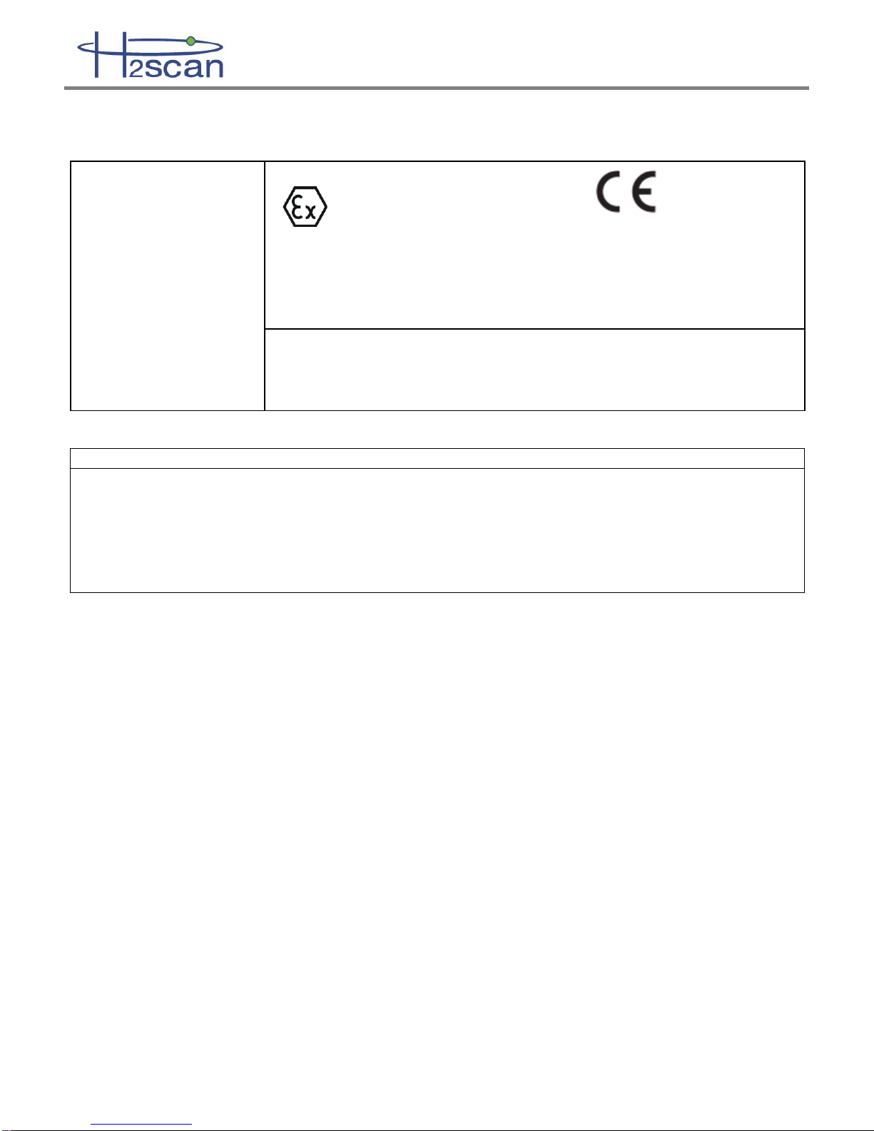
1.4 Analyzer Certifications.................................................................................................. 9
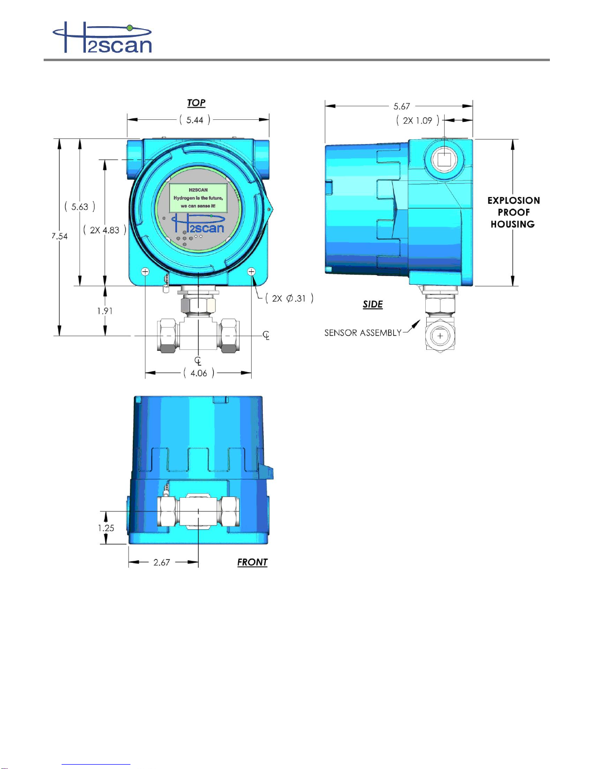
1.5 Dimensions................................................................................................................. 10
Chapter 2: Installation
2.1 Opening the Analyzer ................................................................................................. 11
2.2 Wiring ......................................................................................................................... 13
2.2.1 AC Power Wiring...................................................................................................15
2.2.2 Relay Wiring..........................................................................................................15
2.2.3 Pressure Sensor Wiring (Optional)........................................................................15
2.2.4 4-20mA Interface Wiring........................................................................................16
2.2.5 Serial Interface Wiring...........................................................................................16
2.3 Relays......................................................................................................................... 16
2.4 Analyzer Mounting...................................................................................................... 17
2.5 Startup........................................................................................................................ 18
2.5.1 Models 2710, 2730, 2740......................................................................................18
2.5.2 Model 2720 ...........................................................................................................18
2.6 Shutdown.................................................................................................................... 18
Chapter 3: Operation and Configuration
3.1 Optimum Analyzer Performance................................................................................. 19
3.1.1 Effect of Pressure..................................................................................................19
3.1.2 Calibration Gas Bottle Accuracy............................................................................19
3.2 Pressure Sensor (Optional) ........................................................................................ 19
3.2.1 Pressure Sensor Installation .................................................................................20
3.2.2 Pressure Sensor Configuration .............................................................................20
3.2.3 Pressure Sensor Installation Troubleshooting.......................................................22
3.3 Cleaning ..................................................................................................................... 22
3.4 Analog Output............................................................................................................. 22
3.5 Serial Communication................................................................................................. 23
3.5.1 Serial Commands Summary .................................................................................23
3.5.2 A Command (Relays)............................................................................................24
3.5.3 CI Command (Calibrate Analog Output)................................................................25
3.5.4 D Commands (Display Product Information).........................................................25
3.5.5 G Command (Go, Stream Data)............................................................................25
3.5.6 H Command (Modify H2 Reporting Range)...........................................................26
3.5.7 I Command (Modify Analog Output)......................................................................26
3.5.8 PS Command (Configure Pressure Sensor) .........................................................27
3.5.9 SV Command (User Selectable Averaging) ..........................................................27

HY-OPTIMA™ 2700 Series ATEX Operating Manual
90000079 R8Page 4 of 45
3.5.10 T Command (Data Log).........................................................................................28
3.5.11 X Command (Clear Field Cal) ...............................................................................29
3.5.12 F Command (Perform Field Cal) ...........................................................................29
3.6 Display Menus............................................................................................................ 29
3.6.1 Intrinsically Safe Infrared Remote Control.............................................................29
3.6.2 Intrinsically Safe Requirements.............................................................................29
3.6.3 Navigating the Display Menus...............................................................................31
Chapter 4: Field Calibration
4.1 Calibration Interval...................................................................................................... 32
4.2 Calibration Gases....................................................................................................... 32
4.2.1 Background Gases................................................................................................32
4.3 Calibration Procedure................................................................................................. 33
4.3.1 Procedure Using the Remote Control....................................................................33
4.3.2 Procedure Using the Serial Interface.....................................................................36
4.3.3 Clear Field Calibration (Restore Factory Calibration)............................................36
Chapter 5: Supplemental Information and Troubleshooting
5.1 Storage....................................................................................................................... 37
5.1.1 Storage Oxidation & Offsets..................................................................................37
5.1.2 Expected Oxidation Time and Recovery Time ......................................................37
5.1.3 Conditioning to Remove an Oxidation Offset ........................................................37
5.1.4 Avoiding a Storage Oxidation Offset .....................................................................38
5.2 Sensor Behavior......................................................................................................... 38
5.2.1 H2 Measurement...................................................................................................38
5.2.1.1 Inert Backgrounds .......................................................................................... 38
5.2.2 H2 Detection..........................................................................................................38
5.2.3 Diurnal Effect.........................................................................................................38
5.3 General Troubleshooting ............................................................................................ 39
5.4 Command Terminal Messages................................................................................... 40
5.5 Serial Communication Troubleshooting...................................................................... 40
5.5.1 Connections ..........................................................................................................41
5.5.2 COM Port Number.................................................................................................41
5.5.3 USB Adaptor Device Driver:..................................................................................41
5.5.4 Rebooting..............................................................................................................41
5.5.5 Terminal Program..................................................................................................42
5.5.6 Analyzer Command Line.......................................................................................42
5.6 Analog Output Troubleshooting.................................................................................. 42
5.6.1 Verify the hydrogen values....................................................................................42
5.6.2 Verify the H2 range ...............................................................................................42
5.6.3 Verify the Analog Output .......................................................................................43
5.6.4 Verify the SCADA analog input .............................................................................43
5.6.5 Calibrate the Analog Output..................................................................................43
Appendix A: Spare Parts...................................................................................................... 44
Appendix B: Foxterm Setup................................................................................................. 45

HY-OPTIMA™ 2700 Series ATEX Operating Manual
90000079 R8Page 5 of 45
IMPORTANT NOTICES
LIMITED WARRANTY
H2scan Limited Warranty: Each hydrogen instrument (“Product”) will conform, as to all substantial operational features, to the Product
specifications set forth in this Manual and will be free of defects which substantially affect such Product’s performance for twelve (12) months
from the ship date for such Product.
Must Provide Notice of Defect: If you believe a Product that you believe is defective, you must notify H2scan in writing, within ten (10) days
of receipt of such Product, of your claim regarding any such defect.
Return Product to H2scan for Repair, Replacement or Credit:If the Product is found defective by H2scan, H2scan’s sole obligation under
this warranty is to either (i) repair the Product, (ii) replace the Product, or (iii) issue a credit for the purchase price for such Product, the
particular remedy to be determined by H2scan on a case-by-case basis.
Voided Warranty: H2scan’s 12 Month Limited Warranty is void for any of the following:
The unit is opened and the manufacturing seal is broken
Unauthorized repair work performed at the customer’s location or carried out by anyone other than H2scan’s factory trained technicians
Equipment or parts that have been tampered with, misused, neglected, mishandled, improperly adjusted, or modified in any way without the
written consent of H2scan.
Equipment or parts that have been damaged due to shipping, misuse, accidents, mishandling, neglect, or problems with electrical power
sources.
Repair work performed during the warranty period does not prolong the warranty period past the original period.
System operation in incorrect or inappropriate environments.
Usage that is not in accordance with system guidelines or an operator’s failure to follow manual instructions.
LIMITATION OF WARRANTY: THE ABOVE IS A LIMITED WARRANTY AS IT IS THE ONLY WARRANTY MADE BY H2SCAN. H2SCAN
MAKES NO OTHER WARRANTY EXPRESS OR IMPLIED AND EXPRESSLY EXCLUDES ALL WARRANTIES OF MERCHANTABILITY
AND FITNESS FOR A PARTICULAR PURPOSE. YOUR SOLE REMEDY HEREUNDER IS REPAIR OR REPLACEMENT OF THE
PRODUCT OR A CREDIT FOR THE PURCHASE PRICE FOR SUCH PRODUCT, THE PARTICULAR REMEDY TO BE DETERMINED BY
H2SCAN ON A CASE-BY-CASE BASIS. H2SCAN SHALL HAVE NO LIABILITY WITH RESPECT TO ITS OBLIGATIONS UNDER THIS
AGREEMENT FOR CONSEQUENTIAL, EXEMPLARY, OR INCIDENTAL DAMAGES EVEN IF IT HAS BEEN ADVISED OF THE
POSSIBILITY OF SUCH DAMAGES. THE STATED EXPRESS WARRANTY IS IN LIEU OF ALL LIABILITIES OR OBLIGATIONS OF
H2SCAN FOR DAMAGES ARISING OUT OF OR IN CONNECTION WITH THE DELIVERY, USE OR PERFORMANCE OF THE
PRODUCTS.
Read and understand this operating manual before installing or using the unit.
Only use cables from H2scan with this unit.
If this equipment is used in a manner not specified by H2scan, the protection provided by this equipment may be impaired.
Hydrogen is flammable at 4% in air. Take indications seriously and be prepared to take action. In the event of detection of 4% or higher
of a hydrogen gas concentration there is a high probability of a hazard to safety. Inform local emergency response personnel
immediately.
Do not apply power to the analyzer if the sensing element is exposed to air, with the exception of Model 2720 Analyzers. This could
severely affect accuracy and stability.
LIMITATION OF LIABILITY - SELLER SHALL UNDER NO CIRCUMSTANCES BE LIABLE FOR ANY INCIDENTAL, CONSEQUENTIAL,
SPECIAL, PUNITIVE, OR OTHER DAMAGES, INCLUDING, BUT NOT LIMITED TO, LOSS OF BUSINESS OR PROFIT, PROMOTIONAL OR
MANUFACTURING EXPENSES, INJURY TO REPUTATION, OR LOSS OF CUSTOMER, BASED ON ANY ALLEGED NEGLIGENCE, BREACH
OF WARRANTY, STRICT LIABILITY, BREACH OF CONTRACT, OR ANY OTHER LEGAL THEORY ARISING OUT OF THE USE, MISUSE,
PURCHASE, SALE OR POSSESSION OF ITS GOODS OR ITS PERFORMANCE OF THIS CONTRACT TO THE EXTENT THAT SUCH
LIABILITY EXTENDS SELLER’S OBLIGATIONS BEYOND THE PRICE PAID BY BUYER TO SELLER FOR THE ITEM ON WHICH SUCH CLAIM
IS BASED. SELLER ADVISES BUYER TO PERFORM ACCEPTABLE TESTS ON ALL HARDWARE PRIOR TO DEPLOYMENT AND TO
PERFORM MAINTENANCE AS DESCRIBED IN THE SELLER’S INSTRUCTION GUIDE. UNDER NO CIRCUMSTANCES SHALL THE
EQUIPMENT PROVIDED HEREUNDER BE USED IN A MANNER WHERE IT IS THE SOLE PROTECTIVE SYSTEM FOR FACILITIES,
EQUIPMENT AND PERSONNEL SAFETY; THE EQUIPMENT IS INTENDED FOR USE IN CONJUNCTION WITH OTHER APPROPRIATE
PROTECTIVE SYSTEMS.

HY-OPTIMA™ 2700 Series ATEX Operating Manual
90000079 R8Page 6 of 45
Chapter 1: Model Specifications and Certifications
1.1 Description
The HY-OPTIMA™ 2700 Series, Explosion Proof In-line Hydrogen Process Analyzer is designed to detect and/or
measure hydrogen using a solid-state, non-consumable sensor that is configured to operate in process gas
streams. The H2scan thin film technology provides a direct hydrogen measurement that is not cross sensitive to
other gases. The hydrogen specific solid-state sensing element is designed for ease of use, interface flexibility
and true process control. The analyzer contains all the circuitry necessary to operate the sensor and present
calibrated hydrogen readings to an analog current output and an RS232 or RS422 digital output. The analyzer is
ideal for hydrogen production and petrochemical applications where real-time measurements can enhance
process plant efficiencies, diagnostics, and maintenance management.
1.2 Models
The HY-OPTIMATM 2700 Series product family includes sensor types that are designed for specific hydrogen
ranges, corrosive gas tolerances and operation when no hydrogen is present. See the guide below for more
details.
MODEL
Hydrogen
Range
Hydrogen
MUST be
present
CO
Limit
H2S
Limit
Calibration
Background
Gas
Max
Pressure
Min
Max
2710
0.1%
10%
Yes
<100 ppm
<20 ppm
N2
1.1 atm
2730
0.5%
100%
Yes
<100 ppm
<1000 ppm
N2
1.1 atm
2740
0.5%
100%
Yes
20%
3%
N2
1.1 atm
2720
0.4%
5%
No1
0
0
O2, N2
1.1 atm
Notes:
1. 2720 models operated in background streams in which H2 is not typically present and may be operated in
an Air, O2, or N2 background.
1.2.1 Model 2710
The HY-OPTIMATM 2710 Process Hydrogen Analyzer has been specifically manufactured to operate in low
hydrogen conditions with increased accuracy.
•Hydrogen Range:
o0.1% to 10% hydrogen by volume at 1.0 atm
•CO and H2S tolerance:
oCO tolerance: 100 ppm
oH2S tolerance: 20 ppm
1.2.2 Model 2720
The HY-OPTIMATM 2720 Process Hydrogen Analyzer has been specifically manufactured to operate in an air or
inert background.

HY-OPTIMA™ 2700 Series ATEX Operating Manual
90000079 R8Page 7 of 45
•Operation in background streams in which H2 is not typically present
•Calibration Background Gas: Air or Inert
•Hydrogen Sensitivity Range:
o0.4% to 5% hydrogen by volume at 1.0 atm
o10% to 125% hydrogen lower flammability limit
Note:
Please disregard all warnings and statements to avoid operation in air or oxygen background; these warnings and
statements do not apply to the HY-OPTIMATM 2720 Explosion Proof In-Line Process Hydrogen Analyzers which
have been manufactured for implementation in background gas streams with air.
HY-OPTIMA™ 2720 Explosion Proof In-Line Process Hydrogen Analyzers operating in air do not require the
conditioning procedure.
H2scan recommends the hydrogen gas concentrations for both the Field Verification and Field Calibration gases
to be 1% and 2% hydrogen in a balance of air.
1.2.3 Model 2730
The HY-OPTIMATM 2730 Process Hydrogen Analyzer has been specifically manufactured to operate in full range
(0.5% to 100%) hydrogen conditions with the following enhanced tolerances to CO and H2S in process gas
streams:
•CO tolerance: 100 ppm
•H2S tolerance: 1000 ppm
1.2.4 Model 2740
The HY-OPTIMATM 2740 Process Hydrogen Analyzer has been specifically manufactured to operate in full range
hydrogen conditions with the following enhanced tolerances to CO and H2S in process gas streams:
•CO tolerance: 20% by volume
•H2S tolerance: 3% by volume

HY-OPTIMA™ 2700 Series ATEX Operating Manual
90000079 R8Page 8 of 45
1.3 Specifications
1.3.1 Performance Specifications
MODEL
Hydrogen
Range
Hydrogen
MUST be
present
CO
Limit
H2S
Limit
T90
Response
Time (sec)
Accuracy
Drift/Week
Repeatability
Linearity
Min
Max
Min to
10% H2
10 to
Max% H2
Min to
10% H2
10 to
Max% H2
Min to
10% H2
10 to
Max% H2
Min to
10% H2
10 to
Max% H2
2710
0.1%
10%
Yes
<100 ppm
<20 ppm
< 90
0.15%
N/A
0.15%
N/A
0.15%
N/A
0.15%
N/A
2730
0.5%
100%
Yes
<100 ppm
<1000 ppm
< 60
0.3%
1.0%
0.2%
0.4%
0.2%
0.4%
0.2%
0.4%
2740
0.5%
100%
Yes
20%
3%
< 90
0.3%
1.0%
0.2%
0.4%
0.2%
0.4%
0.2%
0.4%
2720
0.4%
5%
No1
0
0
< 60
0.3%
N/A
0.3%
N/A
0.3%
N/A
0.3%
N/A
Note: Sensor performance specifications are absolute and assume a dry process stream, an ambient temperature of 25°C, pressure compensation, and are in
addition to any errors in the calibration gases used. The accuracy is specified for the serial port and digital display output only.
1. 2720 models operated in background streams in which H2 is not typically present and may be operated in an Air, O2, or N2 background.
1.3.2 Operating Specifications
Sample Gas Flow Rate
0.1 to 10 slpm (1.0 slpm is recommended)
Temperature
Gas Stream: -20°C to +60°C
Sensor Ambient Temperature: -20°C to +55°C
Storage: -30°C to +80°C
Intrinsically Safe Infrared Remote Control Ambient Temperature: -20°C to +55°C
Input Power
90VAC to 240VAC, 15W, 50Hz to 60Hz
Analog Output
Isolated and self-powered 4 –20mA,
Maximum load impedance: 650Ω
Conduit Size
¾ inch NPT
Process Gas Pressure
1.1 atm max
Relay Contacts
Three programmable SPDT relays with both normally open (N.O.) and normally
closed (N.C.) contacts.
5A, 240VAC max General Use
Serial Communication
RS232 or RS422
19200 bps, No parity, 8 bit data, 1 stop bit, No flow control (preferred) or Xon/Xoff
Weight
2.7kg (5.9lbs)
Safety Information for Maintenance and Repair
No maintenance is required.

HY-OPTIMA™ 2700 Series ATEX Operating Manual
90000079 R8Page 9 of 45
1.4 Analyzer Certifications
Certifications:
DEMKO 11 ATEX 1107270 X
IEC 60079-0, 6th edition; EN 60079-0:2012+A11:2013 - Electrical Apparatus For
Explosive Gas Atmospheres. Pt. 0, General Requirements
IEC 60079-1, 7th edition; EN 60079-1:2014 - Electrical Apparatus For Explosive
Gas Atmospheres. Pt. 1, Flameproof "d"
IECEx UL 16.0054X
Ex db IIB + H2 T4 Gb
IEC 60079-0 Ed. 6, IEC 60079-1 Ed. 7
Special Conditions of Safe Use (ATEX)
The sensor housing is not to be used with pressure lines containing gas which is capable of forming an explosive
mixture with air and is at a pressure in excess of 1.1 times atmospheric pressure.
The flameproof joints are not intended to be repaired; contact H2scan for information.
The hydrogen sensor element inside the tube is not intended for repair, the assembly containing the sensor
element may be replaced at an H2scan facility if it is defective; contact H2scan for information.
II 2 G Ex db IIB + H2 T4 Gb
0359

HY-OPTIMA™ 2700 Series ATEX Operating Manual
90000079 R8Page 10 of 45
1.5 Dimensions
(Units in inches)

HY-OPTIMA™ 2700 Series ATEX Operating Manual
90000079 R8Page 11 of 45
Chapter 2: Installation
Safety Information
All cable entry devices, conduit sealing devices, and blanking elements shall be certified in type of explosion
protection flameproof enclosure “d”, suitable for the conditions of use and correctly installed.
Unused apertures shall be closed with suitable blanking elements.
Field wiring shall be suitable for at least 80C.
For ambient temperatures below –10C use field wiring suitable for minimum ambient temperature.
WARNING: H2scan’s HY-OPTIMA™ 2700 Series Explosion Proof In-line Hydrogen Process Analyzers are
calibrated in a hydrogen/nitrogen (H2/N2) background and should NEVER be operated in an air or oxygen
background unless using the 2720 model.
The analyzer can be exposed to oxygen for short periods of time without adverse effects if the analyzer is turned
off. If the analyzer is operated in oxygen or stored in air for longer than a week, the hydrogen readings may be
high due to oxygen adsorption on the sensor. Hydrogen exposure will then cause the readings to drift lower as
adsorbed oxygen is slowly removed and the analyzer recovers to normal steady behavior.
If this drift behavior is observed, the sensor should be conditioned by operating in a hydrogen concentration
exceeding 5% until the readings are stable. The required hydrogen conditioning may vary from several hours to
several days depending on the level of oxygen exposure. Higher hydrogen concentrations used during
conditioning may accelerate the process. Once stable, the analyzer should be checked for accuracy and
calibrated if needed.
2.1 Opening the Analyzer
Safety Information for Assembly/Disassembly
Do not turn on electrical power until the enclosure is fully assembled with the lid secured to the base and all
apertures secured with conduit or blanking element.
Turn off electrical power before disassembly.
WARNING: If the analyzer is installed in a classified location then it is the responsibility of the user and
installer to make connections to related equipment in a manner consistent with the location classification.
To access the Interface Board and Display Board simply unscrew the cover of the explosion proof housing. The
Display Board connects with the Interface Board (shown in Figure 3) via a cable that allows the Display Board to
be moved aside for wiring the analyzer. No tools are required. Ensure all precautions regarding electrostatic
discharge (ESD) are taken.
To remove the Display Board, simply pull it straight up from the posts gripping the PCB. Plug it into another post
to hold it in a convenient spot out of the way as shown in Figure 1. DO NOT unplug the cable.

HY-OPTIMA™ 2700 Series ATEX Operating Manual
90000079 R8Page 12 of 45
Figure 1: Removing the Display Board
If the cable is accidentally unplugged, plug it into the connector marked “INTF” (See Figure 2). Plugging it into any
other connector will damage the Display Board and the Sensor Board.
Figure 2: Display Connections
After wiring is complete (see Section 2.2 Wiring), reinsert the Display Board into the posts.
Further disassembling the analyzer voids the warranty and could cause serious damage. The board directly
beneath the Display Board is the Interface Board. DO NOT disconnect the Interface Board.
DO NOT unplug
this cable
DO NOT unscrew
these posts

HY-OPTIMA™ 2700 Series ATEX Operating Manual
90000079 R8Page 13 of 45
2.2 Wiring
All wiring is done on the Interface Board (Figure 3). The connectors are two piece designs in which the wires are
screwed into a receptacle in standard terminal block style. This is plugged into the board.
Figure 3: Interface Board Showing Connectors
J4 Pin 1
J2 Pin 1
J5 Pin 1
J6 Pin 1

HY-OPTIMA™ 2700 Series ATEX Operating Manual
90000079 R8Page 14 of 45
1. Insert wires through the conduit connections.
2. Strip the insulation off the wires and make the
connections to the connector block.
3. Plug the connector into the receptacle.
4. Pull any excess wire out of the enclosure.

HY-OPTIMA™ 2700 Series ATEX Operating Manual
90000079 R8Page 15 of 45
2.2.1 AC Power Wiring
Power Board: J2 4-Pin Terminal Block for the Power Cable
Pin Number
Function
Description
1
NEUTRAL
Alternating current return
2
LINE
Hot AC power
3
CHASSIS GROUND
Safety connection to ground
4
SIGNAL GROUND
Common ground for sensitive circuitry isolated from chassis ground. If a
signal ground is not available, short this pin with the chassis ground.
Some facilities have separate grounds for signal and AC power. If this is the case run the signal ground and
chassis ground wires to the appropriate locations. If there is one ground, jumper the chassis ground and signal
ground pins together in J2.
2.2.2 Relay Wiring
WARNING: Do not exceed the maximum ratings of the relay contact specifications (5A, 240VAC MAX)
Interface Board: J6 12-Pin Terminal Block for Output Cable
Pin Number
Function
Description
1
ALERT NC
SPDT Relay 1 for the Alert level of hydrogen
2
ALERT COM
3
ALERT NO
4
ALARM NC
SPDT Relay 2 for the Alarm level of hydrogen
5
ALARM COM
6
ALARM NO
7
FAULT NC
SPDT Relay 3 for fault conditions
8
FAULT COM
9
FAULT NO
2.2.3 Pressure Sensor Wiring (Optional)
Interface Board: J6 12-Pin Terminal Block for Output Cable
Pin Number
Marking
Description
10
AUX IN
Signal: 1 to 5V pressure sensor input
11
S GND
Ground: Return for pins 10 and 12
12
NC
Hot: +12VDC
The analyzer is designed for use with a pressure sensor that outputs a 1 –5 volt analog signal and can be
powered by 12 volts.
See Section 3.2 - Pressure Sensor (Optional) for more detailed installation instructions.

HY-OPTIMA™ 2700 Series ATEX Operating Manual
90000079 R8Page 16 of 45
2.2.4 4-20mA Interface Wiring
Interface Board: J5 2-Pin Terminal Block for Output Cable
Pin Number
Function
Description
1
4-20mA+
4-20mA analog output
2
4-20mA -
Hydrogen Level
Power-On Self Diagnostic
Error
4 mA to 20 mA
2 mA
3 mA
0 mA to 20 mA
0 mA
20 mA
The analog output range can be changed in the field. Please refer to Section 3.4 Analog Output.
2.2.5 Serial Interface Wiring
Interface Board: J4 5-Pin Terminal Block for Serial Interface Cable
J3 Pin
Function
Description
1
TxD- (Device Transmit, Negative)
RS422 –Data out –
RS232 –Data Out
2
TxD+ (Device Transmit, Positive)
RS422 –Data out +
RS232 –NC
3
RxD- (Device Receive, Negative)
RS422 –Data In –
RS232 –Data In
4
RxD+ (Device Receive, Positive)
RS422 –Data In +
RS232 - NC
5
SGND
Signal Ground
2.3 Relays
Relay
Usage
1. Alert
A warning that the hydrogen value has exceeded the set point.
2. Alarm
An alarm that the hydrogen value has exceeded the set point.
3. Fault
One of the following faults has occurred:
•PCB temperature is too high
•H2 resistor value is out of range
•Data not valid
•Heater Off Error
•Power Failure (if enabled)
The Alert and Alarm relays can be programmed to respond to user-defined hydrogen levels that suit the
installation. The Alarm relay should be programmed to react to a higher hydrogen level than the Alert relay. The
Fault relay has a Power Fail Indicator feature that may be enabled or disabled.
Selection
Usage
Enabled
Under normal conditions the fault relay is energized with NO connected to COM.
Disabled
Under normal conditions the fault relay is de-energized with NC connected to COM.

HY-OPTIMA™ 2700 Series ATEX Operating Manual
90000079 R8Page 17 of 45
2.4 Analyzer Mounting
Mounting is achieved with two ¼ inch diameter screws through mounting holes in the base of the explosion proof
housing. ¾ inch solid conduit threaded into the enclosure will also serve as further structural support. Conduit
unions are recommended on both sides of the analyzer to prevent damage to its threads in case a high torque is
applied to the conduit. Conduit sealing fittings must be installed within 18” of the analyzer. Additionally it is
recommended the housing be mounted vertically to prevent condensation from affecting the sensor with display
on top and the sensor tube pointing downwards as shown in Figure 4. See the Safety Information at the beginning
of this chapter for information regarding additional safety requirements.
Figure 4: Analyzer Mounting Orientation
Adaptors such as the 4PC12 by Parker can be used to adapt the ¾” ports on the T-Fitting to a ¼” tube.

HY-OPTIMA™ 2700 Series ATEX Operating Manual
90000079 R8Page 18 of 45
2.5 Startup
2.5.1 Models 2710, 2730, 2740
If the analyzer is being turned on from an off position, power on the analyzer before flowing gas across the
sensor. The sequence of steps which are to be followed is:
1. Power on the analyzer and wait for the 5 minute warmup routine to complete.
2. Apply the low span calibration gas to the analyzer and wait for the reading to stabilize (typically 2
hours on first startup). See Section 4.2 Calibration Gases for choosing the low and high span gas
concentrations. Do not apply greater than 10% H2/N2 to the Model 2710.
3. Perform a Field Calibration (see Chapter 4: Field Calibration).
The analyzer can be exposed to oxygen for short periods of time without adverse effects if it is turned off. If it is
stored in air for longer than a week, the analyzer may read higher than the true hydrogen concentration due to
oxygen absorption on the sensor. Steady hydrogen exposure will slowly remove this absorbed oxygen and cause
the analyzer reading to continually drift downward until it reaches the true hydrogen concentration.
If this drift behavior is observed refer to Section 5.1.3 Conditioning to Remove an Oxidation Offset for instructions
and more information.
2.5.2 Model 2720
If the analyzer is being turned on from an off position, power on the analyzer before flowing gas across the
sensor. The sequence of steps which are to be followed is:
1. Power on the analyzer and wait for the 5 minute warmup routine to complete.
2. Apply air for 30 minutes.
3. Perform a Field Calibration (see Chapter 4: Field Calibration).
The analyzer is designed to be exposed to an air or inert background gas where hydrogen is normally absent. For
optimal performance keep any hydrogen exposure to the sensor to less than one hour. If the hydrogen exposure
exceeds this time, the sensor may need to be reconditioned by leaving it powered on in air for at least 24 hours.
2.6 Shutdown
1. Purge the system using gas with a hydrogen concentration of less than 5% H2 or with 100% N2 for 5
minutes.
2. Turn off all gas flow to the analyzer.
3. Power off the analyzer.

HY-OPTIMA™ 2700 Series ATEX Operating Manual
90000079 R8Page 19 of 45
Chapter 3: Operation and Configuration
3.1 Optimum Analyzer Performance
To maximize the performance of the analyzer:
•Verify that all electrical connections are made as recommended. Switching the polarity can cause damage to
the analyzer.
•Verify the process gas stream is properly regulated with a stable pressure and flow between 0.1 and 10 slpm
(1.0 slpm is recommended).
•After installation complete the conditioning steps described in the Section 2.5 Startup and perform a Field
Calibration (Chapter 4: Field Calibration). Use two calibration gases for the Field Calibration for optimal
results.
An optional pressure sensor can be installed to further increase the analyzer’s accuracy. Refer to Section 3.2
Pressure Sensor for more information.
3.1.1 Effect of Pressure
The analyzer is hydrogen specific and sensitive to only the hydrogen partial pressure in the gas stream. Since
changes in total gas pressure will affect the hydrogen partial pressure, they will also affect the analyzer readings.
At 1.0 atm, a 50% H2/N2 mixture will be reported as 50% by the analyzer. At 1.1 atm the reading will increase to
55% and 2.0 atm will result in a reading of 100%. The analyzer is capable of measuring multiple atmospheres of
hydrogen, and readings above 100% H2 are interpreted as hydrogen pressures above 1.0 atm. For example, a
reading of 110% H2 means 1.1 times the hydrogen pressure of a 100% H2 concentration at 1.0 atm. The
analyzers are factory calibrated at 1.0 atm. Performing the Field Calibration at the operating pressure will correct
the hydrogen reading for static pressures. For example, if the local atmospheric pressure is 0.97 atm, doing a
Field Calibration will correct for this assuming the pressure remains static. Installing a pressure sensor allows the
analyzer to compensate for this effect as well as dynamic changes in pressure.
3.1.2 Calibration Gas Bottle Accuracy
The inaccuracy of the gas bottle concentration will directly affect the measured accuracy by the analyzer. During
factory calibration, the analyzers are calibrated with high accuracy gases (as high as +/- 0.02% accurate). It is
strongly recommended that the user perform calibration with similar high accuracy gases to maintain the accuracy
specified in the manual.
3.2 Pressure Sensor (Optional)
The analyzer may use an optional external pressure sensor to compensate for pressure changes in the process
gas stream. A pressure sensor configured for absolute pressure is preferable to a pressure sensor configured for
gauge pressure as it will prevent local barometric fluctuations from influencing the measurements.
Note: In general, if a pressure transducer was calibrated as a pair with the hydrogen analyzer at the factory, it
should remain with the hydrogen analyzer for the lifetime of the hydrogen analyzer. If the factory paired pressure
transducer is replaced or removed, a factory recalibration of the hydrogen analyzer is required.
The analyzer is designed for use with a pressure sensor with a 1 –5V analog output signal and capability of being
powered by 12V DC.
Note: Pressure sensors with a 0 –5V analog output signal may still be used but only the pressure readings in the
1 –5V range will be valid. During configuration the low pressure value must be set to the psi value of the pressure
sensor corresponding to 1V. For example, when using a 0 –5V pressure sensor with a 0 –30 psia range, the low
pressure value must be set to 6 psia. The system would thus have to operate in the 6 –30 psia range.

HY-OPTIMA™ 2700 Series ATEX Operating Manual
90000079 R8Page 20 of 45
3.2.1 Pressure Sensor Installation
Note: If using SB firmware older than 3.00, ensure a computer is available with a serial port and terminal software
set up as this will be necessary to configure the analyzer. See Appendix B: Foxterm Setup for instructions.
The pressure sensor can be placed before or after the analyzer in the process gas stream. There should be no
components or changes in orifice diameter between the pressure sensor and analyzer as this would cause a
pressure differential. For example, devices such as flow meters, moisture filters, and pressure gauges must not
be placed between the pressure sensor and the analyzer in the process gas stream.
Connect the signal, ground, and power of the pressure sensor to pins 10, 11, and 12 of the J6 12-Pos terminal
block on the interface board as shown in Figure 5.
Figure 5: Pressure Sensor Wiring
Interface Board: J6 12-Pos Terminal Block for Output Cable
Pin Number
Marking
Description
10
AUX IN
Signal: 1 to 5V pressure sensor input
11
S GND
Ground: Return for pins 10 and 12
12
NC
Hot: +12VDC
3.2.2 Pressure Sensor Configuration
If the sensor board has a firmware version greater than 3.00 the pressure sensor can be configured using the
display following the procedure below. Otherwise, the pressure sensor must be configured using the serial
interface using the PS command. See Section 3.5 Serial Communication for instructions on establishing serial
communications, and Section 3.5.8 PS Command (Configure Pressure Sensor) on how to configure the pressure
sensor using the serial connection.
1. The main screen is shown below. Access the menus by aiming the remote control just below the display
and pressing the middle button. This will display the Information Menu as follows:
J6 12-Pos Terminal
Block
Wire the pressure
sensor here
H2 67.520%
Press ENTER
to access menus
Sens FW: 3.69
Disp FW: 1.59
Prod SN: A0000001
Mfg Cal 6/15/2016
Ser Port is RS232
This manual suits for next models
3
Table of contents
Other H2Scan Measuring Instrument manuals
Popular Measuring Instrument manuals by other brands

Kirchner und Tochter
Kirchner und Tochter SMB Series Assembly and operating instructions

TC Electronic
TC Electronic LM2 user manual

UTL
UTL UTL260 instruction manual

Dakota Digital
Dakota Digital Odyssey ODY-08-1 quick start guide

Brigade
Brigade Backsense BS-8100 Installation & operation guide

Obdstar
Obdstar X300 M user manual