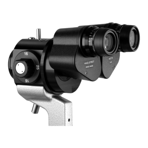
Haag-Streit BI 900 User manual

1
DEUTSCHENGLISH FRANÇAIS ITALIANO ESPAÑOL NEDERLANDS
PORTUGUÊS SVENSKA
DEUTSCHENGLISHFRANÇAISITALIANOESPAÑOLNEDERLANDS PORTUGUÊS
SVENSKA
© HAAG‑STREIT AG, 3098 Koeniz, Switzerland ‑ HS‑Doc. no. 1500.7220505‑04060 – 2021 – 08
INSTRUCTIONS FOR USE
Slit lamp
BI 900¨
6. Edition / 2021 – 08

2
DEUTSCHENGLISH FRANÇAIS ITALIANO ESPAÑOL NEDERLANDS
PORTUGUÊS SVENSKA
© HAAG‑STREIT AG, 3098 Koeniz, Switzerland ‑ HS‑Doc. no. 1500.7220505‑04060 – 2021 – 08
INSTRUCTIONS FOR USE
Slit Lamp
BI 900¨
6. Edition / 2021 – 08
Preface
Thank you for choosing a Haag-Streit device. Provided you comply carefully with the
regulations in these instructions for use, we can guarantee reliable and trouble-free
use of our product.
WARNING!
Read the instruction manual carefully before commissioning this product.
It contains important information regarding the safety of the user and
patient.
NOTE!
For USA only: Federal law restricts this device to sale by or on the order
of a physician or licensed practitioner.
WARNING!
This device is equipped with high intensity light emitting diodes.
Excessive exposure of patients in treatment with certain medication may
lead to phototoxic adverse reactions, due to higher photosensitivity.

3
DEUTSCHENGLISH FRANÇAIS ITALIANO ESPAÑOL NEDERLANDS
PORTUGUÊS SVENSKA
DEUTSCHENGLISHFRANÇAISITALIANOESPAÑOLNEDERLANDS PORTUGUÊS
SVENSKA
© HAAG‑STREIT AG, 3098 Koeniz, Switzerland ‑ HS‑Doc. no. 1500.7220505‑04060 – 2021 – 08
Contents
¥ 1 Safety...................................................................................................................................................4
◦ 1.1 Comments on these instructions for use........................................................................................4
◦ 1.2 Ambient conditions.........................................................................................................................4
◦ 1.3 Shipment and unpacking ...............................................................................................................4
◦ 1.4 Installation warnings ......................................................................................................................4
◦ 1.5 Operation, environment .................................................................................................................5
◦ 1.6 Light toxicity ...................................................................................................................................5
◦ 1.7 Disinfection ....................................................................................................................................6
◦ 1.8 Warranty and product liability ........................................................................................................6
◦ 1.9 Reporting obligation.......................................................................................................................6
◦ 1.10 Description of symbols.................................................................................................................6
¥ 2 Intended purpose / intended use .......................................................................................7
◦ 2.1 Device description..........................................................................................................................7
▪ 2.1.1 Intended users....................................................................................................................7
◦ 2.2 Medical purpose.............................................................................................................................7
▪ 2.2.1 Indications...........................................................................................................................7
▪ 2.2.2 Part of the body ..................................................................................................................7
▪ 2.2.3 Patient population...............................................................................................................7
▪ 2.2.4 Contraindications................................................................................................................7
◦ 2.3 Principles of operation ...................................................................................................................7
▪ 2.3.1 Operating environment .......................................................................................................8
◦ 2.4 Clinical benefit................................................................................................................................8
¥ 3 Introduction .....................................................................................................................................8
◦ 3.1 Overview........................................................................................................................................8
◦ 3.2 Overview LED illumination.............................................................................................................9
◦ 3.3 LED illumination LI02 plus .............................................................................................................9
▪ 3.3.1 Blue filter.............................................................................................................................9
▪ 3.3.2 Background illumination......................................................................................................9
¥ 4 Device assembly / installation ...........................................................................................10
◦ 4.1 Placement of adhesive label for the automatic left/right detection...............................................10
◦ 4.2 Camera assembly........................................................................................................................10
◦ 4.3 Cabling of the RM02 (diagram)....................................................................................................10
◦ 4.4 Microscope and illumination.........................................................................................................11
◦ 4.5 Step-by-step cabling ....................................................................................................................11
¥ 5 Commissioning ...........................................................................................................................13
◦ 5.1 Switching on the device ...............................................................................................................13
¥ 6 Operation.........................................................................................................................................13
◦ 6.1 Setting the eyepieces...................................................................................................................13
◦ 6.2 Field of view.................................................................................................................................13
◦ 6.3 White balance ..............................................................................................................................13
▪ 6.3.1 Slit lamp preparation.........................................................................................................13
▪ 6.3.2 Conducting a white balance..............................................................................................14
◦ 6.4 Software / Help menu / Error messages...................................................................................... 14
◦ 6.5 Preparing the patient ...................................................................................................................14
◦ 6.6 Operating the device ...................................................................................................................14
◦ 6.7 Setting the filters & diaphragms................................................................................................... 16
◦ 6.8 Fixation star................................................................................................................................. 16
◦ 6.9 Microscope and eyepiece............................................................................................................ 16
◦ 6.10 Reduced operation ....................................................................................................................16
◦ 6.11 LED indicator illumination head................................................................................................. 17
◦ 6.12 LED indicator power supply....................................................................................................... 17
◦ 6.13 LED indicator release module RM02......................................................................................... 17
◦ 6.14 LED indicator camera................................................................................................................ 17
◦ 6.15 Error messages (illumination head)........................................................................................... 18
◦ 6.16 Error messages release module RM02..................................................................................... 18
◦ 6.17 Error messages camera ............................................................................................................18
◦ 6.18 Software / Help menu / Error messages.................................................................................... 19
¥ 7 Decommissioning ..................................................................................................................... 19
¥ 8 Technical data ............................................................................................................................. 19
◦ 8.1 Slit illumination............................................................................................................................. 19
◦ 8.2 Power supply............................................................................................................................... 19
◦ 8.3 Stereo microscope....................................................................................................................... 20
◦ 8.4 Instrument base........................................................................................................................... 20
◦ 8.5 Dimensions.................................................................................................................................. 20
◦ 8.6 Camera........................................................................................................................................ 20
◦ 8.7 Minimum PC requirements.......................................................................................................... 20
¥ 9 Maintenance.................................................................................................................................. 21
◦ 9.1 Device inspection ........................................................................................................................21
◦ 9.2 Service......................................................................................................................................... 21
◦ 9.3 Cleaning and disinfection ............................................................................................................ 21
◦ 9.4 Replacing the illumination mirror .................................................................................................21
◦ 9.5 Dust cover ...................................................................................................................................22
¥ 10 Appendix ...................................................................................................................................... 22
◦ 10.1 Accessories / functionals parts / detachable parts / consumables ............................................22
◦ 10.2 Legal regulations .......................................................................................................................22
◦ 10.3 Classification ............................................................................................................................. 22
◦ 10.4 Disposal..................................................................................................................................... 23
◦ 10.5 Observed standards ..................................................................................................................23
◦ 10.6 Information and manufacturer's declaration concerning electromagnetic compatibility (EMC) .23
▪ 10.6.1 General........................................................................................................................... 23
▪ 10.6.2 Emitted interference .......................................................................................................24
▪ 10.6.3 Electromagnetic immunity environment tested (part 1).................................................. 25
▪ 10.6.4 Electromagnetic immunity environment tested (part 2).................................................. 26
▪ 10.6.5 Recommended separation distances between portable and mobile RF communications
equipment and this product....................................................................................................... 28

4
DEUTSCHENGLISH FRANÇAIS ITALIANO ESPAÑOL NEDERLANDS
PORTUGUÊS SVENSKA
© HAAG‑STREIT AG, 3098 Koeniz, Switzerland ‑ HS‑Doc. no. 1500.7220505‑04060 – 2021 – 08
1Safety
DANGER!
Failure to comply with these instructions may result in material damage
or pose a danger to patients or users.
WARNING!
These warnings must absolutely be complied with to guarantee safe
operation of the product and to avoid any danger to users and to
patients.
NOTE!
Important information, please read carefully.
1.1 Comments on these instructions for use
NOTE!
In these instructions for use the point is used as decimal separator.
1.2 Ambient conditions
Temperature −40 °C ... +70 °C
Air pressure 500 hPa ... 1060 hPa
Transport
Relative humidity 10 % ... 95 %
Temperature −10 °C ... +55 °C
Air pressure 700 hPa ... 1060 hPa
Storage
Relative humidity 10 % ... 95 %
Temperature +10 °C ... +35 °C
Air pressure 800 hPa ... 1060 hPa
Use
Relative humidity 30 % ... 90 %
1.3 Shipment and unpacking
• Before unpacking the device, check whether the packaging shows traces of
improper handling or damage. If this is the case, notify the transport company
that delivered the goods to you.
• Unpack the device together with a representative of the transport company.
Make a report of any damaged parts. This report must be signed by you and by
the representative of the transport company.
• Leave the device in the packaging for a few hours before unpacking it
(condensation).
•Check the device for damage after it is unpacked.
• Return defective devices in the appropriate packaging.
• Store packaging material carefully so that it can be used for potential returns or
when moving.
• The slit lamp and headrest must be installed on an electrically insulated,
fireproof table top.
• The rail covers (a) prevent the slit lamp from tilting.
•Check that the connection parts of the accessories are in the correct position
(screw connections, quick-release fasteners).
1.4 Installation warnings
WARNING!
• Do not modify this device without authorization of the manufacturer.
Installation and repairs may only be performed by trained
specialists.
• Any third-party device must be connected in compliance with the EN
60601-1 standard.
• Only original Haag-Streit spare parts may be used.

5
DEUTSCHENGLISH FRANÇAIS ITALIANO ESPAÑOL NEDERLANDS
PORTUGUÊS SVENSKA
DEUTSCHENGLISHFRANÇAISITALIANOESPAÑOLNEDERLANDS PORTUGUÊS
SVENSKA
© HAAG‑STREIT AG, 3098 Koeniz, Switzerland ‑ HS‑Doc. no. 1500.7220505‑04060 – 2021 – 08
• Use of this device adjacent to or stacked with other equipment
should be avoided because it could result in improper operation. If
such use is necessary, this device and the other equipment should
be observed to verify that they are operating normally.
• Grounding reliability can only be achieved when unit is connected to
a hospital grade receptacle. (Not valid for EU countries).
• The device should be set up in such a way that the plug is always
easily accessible and the device can easily be disconnected from
the mains.
1.5 Operation, environment
DANGER!
Never use the device in potentially explosive environments where
volatile solvents (alcohol, petrol, etc.) and flammable anaesthetics are in
use.
WARNING!
• The device must be switched off after every use. Otherwise there is
a risk of overheating when a protective dust cover is used.
• This device must not be operated near of high frequency surgical
equipment and the radio frequency shielded room of a medical
electrical system for magnetic resonance imaging, where the
intensity of electromagnetic disturbances is high.
• Portable radio frequency communications equipment (including
peripherals such as antenna cables and external antennas) should
be used no closer than 30 cm (12 inches) to any part of the device,
including cables specified by Haag-Streit. Otherwise, degradation of
the performance of this device could result.
NOTE!
• This device must only be operated by qualified personnel. The
owner is responsible for their training.
• This device may only be used in accordance with the instructions in
the 'Intended purpose / intended use' chapter.
• If unexpected disturbances are observed which manifest themselves
as communication problems between the imaging module and the
EyeSuite software, the cause could be a cell phone or a radio
frequency telephone in the immediate vicinity to the slit lamp or
power supply. Increase the distance to the unit until the interference
disappears.
•The communication between imaging module and PC may also be
disturbed or interrupted, if the device is exposed to a mains power
supply delivering excessively transient disturbances or short voltage
interruptions. If this happens, the USB connector needs to be
disconnected for a short time or the PC needs to be restarted.
1.6 Light toxicity
WARNING!
• The light from this device may be dangerous. The risk of eye
damage increases with the exposure time. An exposure time with
this device at maximum intensity of longer than 131 seconds
exceeds the guideline value for a risk.
• As extended, intensive illumination can damage the retina, the use
of the device in the examination of the eye should not be prolonged
unnecessarily. The illumination of this slit lamp emits a radiation in
the range between 400 and 750 nm. Detailed information on the
radiation can be provided on request.
• The retinal dose for a photochemical risk is composed of the product
of the radiance and the exposure time. If the radiance is halved, the
time until the exposure time limit value is reached will double
accordingly. To date, no acute, optical radiation hazard has been
detected in slit lamps. Nevertheless, we recommend keeping the
intensity of the light reaching the patient's retina to the minimum
possible for the respective diagnosis. Children, people with aphakia
and people suffering from eye conditions are most at risk. An
increased risk may also occur if the retina is exposed to the same or

6
DEUTSCHENGLISH FRANÇAIS ITALIANO ESPAÑOL NEDERLANDS
PORTUGUÊS SVENSKA
© HAAG‑STREIT AG, 3098 Koeniz, Switzerland ‑ HS‑Doc. no. 1500.7220505‑04060 – 2021 – 08
a similar device with a visible light source within 24 hours. This
applies, in particular, if the retina has been photographed with a
flashbulb in advance.
1.7 Disinfection
NOTE!
The device can, but does not need to be disinfected. For more
information, please refer to the 'Maintenance' chapter.
1.8 Warranty and product liability
• Haag-Streit products must be used only for the purposes and in the manner
described in the documents distributed with the product.
• The product must be treated as described in the ‘Safety’ chapter. Improper
handling can damage the product. This would void all guarantee claims.
•Continued use of a product damaged by incorrect handling may lead to personal
injury. In such a case, the manufacturer will not accept any liability.
• Haag-Streit does not grant any warranties, either expressed or implied, including
implied warranties of merchantability or fitness for a particular use.
• Haag-Streit expressly disclaims liability for incidental or consequential damage
resulting from the use of the product.
• This product is covered by a limited warranty granted by your seller.
• For USA only: This product is covered by a limited warranty, which may be
reviewed at www.haag-streit-usa.com.
1.9 Reporting obligation
NOTE!
Any serious incident that has occurred in relation to the device must be
reported to Haag-Streit and the competent authority of the Member
State in your country.
1.10 Description of symbols
Follow instruction for use Read the instructions for use
attentively
General warning, read the
accompanying documentation
European certificate of
conformity
Date of manufacture Manufacturer
Haag-Streit reference number Serial number
Trademark of the manufacturer
Haag-Streit AG
Notes on disposal, see the
'Disposal' chapter
Listed European Authorized
Representative Medical Device
Testsymbol of TÜV Rheinland
with approval for INMETRO
Brasil
MET Listed Mark with approval
for USA and Canada
Plug socket USB 3.0 micro B
on RM02 for computer
Plug socket USB 3.0 on RM02
for camera
Strong permanent magnets Plug socket on RM02 for power
supply
Slit lamp illumination Background illumination
On (Power)

7
DEUTSCHENGLISH FRANÇAIS ITALIANO ESPAÑOL NEDERLANDS
PORTUGUÊS SVENSKA
DEUTSCHENGLISHFRANÇAISITALIANOESPAÑOLNEDERLANDS PORTUGUÊS
SVENSKA
© HAAG‑STREIT AG, 3098 Koeniz, Switzerland ‑ HS‑Doc. no. 1500.7220505‑04060 – 2021 – 08
2Intended purpose / intended use
A slit lamp biomicroscope is intended for use in eye examination. It is used to aid in
the diagnosis and documentation of diseases or trauma which affect the structural
properties of the eye.
2.1 Device description
The devices of the slit lamp are made up of:
• Stereo biomicroscope
• Slit illumination
• Instrument base
• Headrest and chin rest
The illumination system and a biomicroscope are mounted to an instrument base
operated by joystick. The single joystick allows horizontal and vertical displacement
of the slit lamp across the examination table. Both elements, the illumination system
and the biomicroscope, can be swiveled progressively across the pivot,
independently of one another.
A sturdy headrest is attached to the table. Both the table and the chin rest are
adjustable in height to provide a comfortable, yet sturdy examination position to the
patient, outside of the device's range of motion. As this device operates non-
invasively it only comes into contact with the patient at the chin rest and forehead
band.
2.1.1 Intended users
Users are qualified medical professionals such as ophthalmologists, optometrists,
opticians, nurses and researchers or other qualified specialists as permitted by local
legislation.
2.2 Medical purpose
This device has the following medical purpose:
• Diagnosis and monitoring of diseases of the anterior segment of the eye
• Diagnosis and monitoring of injuries of the anterior segment of the eye
• Investigation of the anatomy and physiological or pathological state of the
anterior segment of the eye
2.2.1 Indications
The use of the slit lamp is indicated for the following medical conditions:
• Local and systemic diseases affecting the eye
• Lesions and defects of the anterior segment
• Acute infections and inflammations
• Presence of intraocular foreign bodies
• Other traumata of the eye
2.2.2 Part of the body
The slit lamp is intended for the examination of the human eye, specifically the
anterior segment of the eye (i.e., lids, lashes, conjunctiva, cornea, anterior chamber,
iris, and lens).
2.2.3 Patient population
This device is intended for use on human patients with the physical ability to sit in
front of a slit lamp with their head resting against the headrest in a steady position
and the mental ability to follow instructions.
2.2.4 Contraindications
There are no known contraindications.
2.3 Principles of operation
• The slit lamp implements the principle of focal illumination: The focal point of the
microscope and the illumination coincide.
• The microscope arm and the illumination arm are mounted on an instrument
base: Both can be swivelled independently around the same vertical axis.
• The instrument base can be moved in all three axes.
• When illuminating transparent media with a narrow, sharp slit, an 'optical
section' can be magnified and viewed through the microscope.
• The patient's head is fixed to a height-adjustable headrest holder so that the
examination can be carried out quickly and as comfortably as possible for both
doctor and patient.

8
DEUTSCHENGLISH FRANÇAIS ITALIANO ESPAÑOL NEDERLANDS
PORTUGUÊS SVENSKA
© HAAG‑STREIT AG, 3098 Koeniz, Switzerland ‑ HS‑Doc. no. 1500.7220505‑04060 – 2021 – 08
2.3.1 Operating environment
The slit lamp is intended to be used in professional health care facilities such as
hospitals, physician's, optometrist's and optician's practices. For optimal use of the
slit lamp, the ambient lighting should be attenuated to improve image contrast. In
case of transillumination of the iris or for viewing details at great magnification at a
narrow slit, it may be necessary to completely darken the room.
2.4 Clinical benefit
The use of the slit lamp allows for the systematic examination of the eye under
magnification, thus permitting the diagnoses of pathologies that may have otherwise
remained unidentified and could have lead to blindness if left untreated.
The clinical benefits of the product outweigh the remaining residual risks to the
patient.
3Introduction
The slit lamp consists of an illumination and a binocular microscope. The instrument
base can be used to move the entire device in front of the eyes. The illumination
offers a large number of setting options to make the practically invisible areas in the
eye visible. There is also a range of accessories available for the slit lamp to allow
special diagnosis possibilities in addition to the general examinations.
NOTE!
The BI 900 slit lamp can be optionally equipped with the imaging set
(REF 7220535).
3.1 Overview
1. Lamp cable
2. LED illumination LI 900
3. Filter lever
4. Optical light guide for background
illumination (option)
5. Slit length, slit rotation, blue filter
and fixation star control, knob for
rotating the slit
6. Scale for angled position of the slit
image (5° increments)
7. Background illumination FI01f
(option)
8. Illumination mirror
9. Diffusing lens
10. Headrest (see separate
instructions)
11. Protective cover
12. Illumination unit / microscope
angle scale
13. Illumination arm locking screw
14. Microscope arm locking screw
15. Camera cable (option)
16. Release module RM02
17. Sticker left/right identification
18. Axle
19. Rail cover
20. Cover cap for the accessories
base
21. Stereo microscope
22. Eyepieces
23. Mounting screw for breath shield
(option)
24. Breath shield (option)
25. Centring screw for illumination
26. Camera operational control LED
(option)
27. Inclination angle latch 0 – 20°
28. Slit width controls
29. Roller rail
30. Control lever
31. Camera (option)
32. Slide plate
33. EyeSuite Imaging software
(option)
34. Power supply
35. Electric power supply lead (country
dependent)

9
DEUTSCHENGLISH FRANÇAIS ITALIANO ESPAÑOL NEDERLANDS
PORTUGUÊS SVENSKA
DEUTSCHENGLISHFRANÇAISITALIANOESPAÑOLNEDERLANDS PORTUGUÊS
SVENSKA
© HAAG‑STREIT AG, 3098 Koeniz, Switzerland ‑ HS‑Doc. no. 1500.7220505‑04060 – 2021 – 08
3.2 Overview LED illumination
36. LED illumination LI02 plus with background illumination
37. Plug connection
38. Filter wheel for blue filter
39. Connection background illumination
40. Cover
3.3 LED illumination LI02 plus
3.3.1 Blue filter
41. The rotating wheel is used to pivot the blue filter for the background
illumination. Marking points at the same height = blue filter is on.
3.3.2 Background illumination
The background illumination can only be used in conjunction with an LED
illumination LI02 plus.
42. Background illumination fixed
43. Background illumination pivoting (option)

10
DEUTSCHENGLISH FRANÇAIS ITALIANO ESPAÑOL NEDERLANDS
PORTUGUÊS SVENSKA
© HAAG‑STREIT AG, 3098 Koeniz, Switzerland ‑ HS‑Doc. no. 1500.7220505‑04060 – 2021 – 08
4 Device assembly / installation
WARNING!
• Do not modify this device without authorization of the manufacturer.
Installation and repairs may only be performed by trained
specialists.
•Contact your Haag-Streit representative for installation, repairs and
modification work on the system. The contact details are available at
www.haag-streit.com.
• Only original Haag-Streit spare parts may be used.
4.1 Placement of adhesive label for the automatic left/right
detection
• Remove rail cover (19) and place slit lamp aside. Clean surface of table.
• Remove protective film from the back of the adhesive label. Carefully start at the
corner opposite the black surface.
• Position the sticker against the right roller rail (45) and the gliding plate (46).
Press firmly on the white/black surface, press away any air bubbles.
•Carefully tear off the remainder of the adhesive label (44) along the perforation.
• Reassemble the slit lamp and rail cover.
44. Rest of the sticker
45. Roller rail
46. Gliding plate
4.2 Camera assembly
• Remove the cover caps from the camera and adapter.
• Screw the camera (48) onto the adapter.
• Position the image upright setting on the monitor: Slightly loosen the 3 retaining
screws (47), turn the camera around its vertical axis until the position is correct;
reaffix the camera. Through the software, the image can be displayed
horizontally or vertically.
• Mount the camera casing (50) and fix in place with screws (49)
47. Retaining screws
48. Camera
49. Fastening screws
50. Camera casing
4.3 Cabling of the RM02 (diagram)
WARNING!
• Only use the supplied USB 3.0 cable (REF 1022373) for the
connection to the PC.
•Only use medically approved PCs or operate via a medically
approved isolating transformer.
•Auxiliary units on the PC (e.g. printer, monitor) must be operated
through an isolating transformer.
• Ethernet may only be used through a galvanic isolation in
accordance with EN 60601-1.
• The power supply unit's mains connector must be accessible in
order to allow for disconnection from the electric mains at any time.

11
DEUTSCHENGLISH FRANÇAIS ITALIANO ESPAÑOL NEDERLANDS
PORTUGUÊS SVENSKA
DEUTSCHENGLISHFRANÇAISITALIANOESPAÑOLNEDERLANDS PORTUGUÊS
SVENSKA
© HAAG‑STREIT AG, 3098 Koeniz, Switzerland ‑ HS‑Doc. no. 1500.7220505‑04060 – 2021 – 08
51. Mains
52. Medical approved isolating
transformer
53. Instrument table
54. Medical approved power supply
55. Printer
56. Screen
57. Personal computer
58. Local network
59. Galvanic isolation (EN 60601-1)
60. Headrest
61. Cable headrest / LED illumination /
RM02
62. Release module RM02
63. LED illumination
64. Camera
NOTE!
To ensure that the system works correctly, Haag-Streit recommends not
using laptops and using a high-quality desktop computer instead.
65. Fastening screw
66. Two-pole connection plug
If the middle LED lights up red
during operation, the two-pole
connection plug (66) is
connected incorrectly.
• Disconnect the device from the mains.
• Remove the cover on the upper part of the illumination facility by loosening the
fastening screw (65).
• Turn the two-pole connection plug (66) 180°.
• Fix the cover on the upper part of the illumination facility with the fastening
screw (65).
•Connect the device to the mains again.
WARNING!
• Keep magnet-sensitive storage media (e.g. credit cards) away from
the magnets on the release module RM02.
• Only external medical power supplies approved by Haag-Streit that
fulfill EN 60601-1 may be used.
4.4 Microscope and illumination
• The slit lamp is packaged and delivered fully assembled. The transport safety
devices must be removed prior to commissioning.
• Fix the breath shield (24) in place by fastening the mounting screw (23) on the
inside of the bearer arm.
The small screw in the centre of the right control knob (A)
allows you to regulate the friction of the turning movement
of these adjusting knobs. Turning it slightly to the right (in)
makes it harder, turning it left (out) makes it easier. It
should at least be set so hard that the slit cannot close on
its own.
4.5 Step-by-step cabling
• Place the release module RM02 (73) over the slit lamp's cross slide. Four
magnets are used for fixing.
NOTE!
No external USB devices may be connected to USB ports (85) and (87).

12
DEUTSCHENGLISH FRANÇAIS ITALIANO ESPAÑOL NEDERLANDS
PORTUGUÊS SVENSKA
© HAAG‑STREIT AG, 3098 Koeniz, Switzerland ‑ HS‑Doc. no. 1500.7220505‑04060 – 2021 – 08
• Insert the camera cable's connector plug (76) into the socket (85).
• Press the cable into the recess on the microscope arm (75).
• Feed computer cable USB 3.0 (73), power supply cable (72), and cable
headrest / LED illumination / RM02 (71) through the braided sleeving (70).
• Insert the connector plug of the power supply cable (72) into the socket (86).
• Insert the connector plug of the computer cable USB 3.0 (73) into the (87).
• Pull on the braided sleeving until taut and mount a cable tie (69) on each end.
• Mount a cable cover (91) on the threaded bolts (88) or mount the USB
connector screws.
•Connect the headrest cable (68) with its counterpart (67) on the headrest.
• Mount the table board and place the slit lamp on the table.
•Connect the computer cable USB 3.0 (73) to the PC.
•Connect the electric power supply lead (35) to the power supply (34).
•Connect the power supply connector plug to the mains.
• Plug the headrest cable (1) into the lamp head.
67. Connection plug headrest
68. Connector plug headrest / LED
illumination / RM02
69. Cable tie
70. Braided sleeving
71. Cable headrest / LED illumination /
RM02
72. Power supply cable
73. Computer cable USB 3.0
74. Camera (not shown)
75. Recess on the microscope arm
76. Connector plug camera cable
77. Release module RM02
78. RM02 operational control LED
79. On/Off key
80. Rotating knob, background
illumination
81. Rotating knob, slit illumination
82. Selector key A
83. Selector key B
84. Release key RM02
85. Socket camera cable
86. Socket for power supply connector
plug
87. Socket computer cable USB 3.0
micro B
88. Threaded bolt
89. Pin assignment without imaging
set
90. Pin assignment with imaging set
91. Cable cover

13
DEUTSCHENGLISH FRANÇAIS ITALIANO ESPAÑOL NEDERLANDS
PORTUGUÊS SVENSKA
DEUTSCHENGLISHFRANÇAISITALIANOESPAÑOLNEDERLANDS PORTUGUÊS
SVENSKA
© HAAG‑STREIT AG, 3098 Koeniz, Switzerland ‑ HS‑Doc. no. 1500.7220505‑04060 – 2021 – 08
5 Commissioning
5.1 Switching on the device
•Connect the power supply to the mains and press the On/Off key (79) on the
release module RM02. The green operational control LED (78) lights up when
the device is switched on. The camera has no On/Off key and switches on
automatically when the PC is switched on.
• Turn the rotating knob on the slit illumination (81) to a position between '1' and
'10'.
6Operation
6.1 Setting the eyepieces
NOTE!
The eyepieces must be individually set prior to the first examination in
accordance with the refraction of the examiner. Insert the adjusting pin
(92) provided in place of the protective cover (93) and turn its black
projection surface at a right angle to the microscope axis. Return the
illumination and microscope to the central position (0°).
92. Adjusting pin
93. Protective cover
94. Sliding occluders
• Each eyepiece should be set individually by turning the knurled ocular refraction
ring with dioptre scale until the projected slit can be seen in focus. The setting is
performed from the (+) to the (-) side at low magnification.
• The sliding occluders (94) are used to set the correct working distance for the
examiner from the eyepiece.
• Examiners who do not wear glasses: Pull the occluders out as far as they will
go.
• Examiners who do wear glasses: Push the occluders in as far as they will go.
6.2 Field of view
WARNING!
The images and videos should only be used for documentation
purposes. Only the image in the eyepiece may be used for diagnosis.
Field of view of the object, see table
Circle: The field of view of the object observed through the microscope's
eyepiece.
Rectangle: Surface area of the sensor:
Object image section in the
eyepiece (mm)
Object image section in the
camera (mm)
1 × ø 18 24 × 32
1.6 × ø 11.25 15 × 20
6.3 White balance
The image quality is dependent on the correct calibration of the color tones to the
respective slit lamp illumination. We recommend performing a white balance in order
to improve the image quality and achieve a realistic color reproduction.
6.3.1 Slit lamp preparation
1. Turn the slit lamp on.
2. Filter position 'open' (no filter).
3. Select a 16 × magnification.
4. Completely open the slit diaphragm.
5. Connect the diffuser upstream.

14
DEUTSCHENGLISH FRANÇAIS ITALIANO ESPAÑOL NEDERLANDS
PORTUGUÊS SVENSKA
© HAAG‑STREIT AG, 3098 Koeniz, Switzerland ‑ HS‑Doc. no. 1500.7220505‑04060 – 2021 – 08
6. Position the Haag-Streit greycard in front of the slit lamp and use it for
focusing.
7. The brightness of the slit lamp's illumination should be set in such a way that
the greycard's structure is clearly discernible.
6.3.2 Conducting a white balance
1. Start the 'EyeSuite Imaging' software
2. Activate the intensity auto mode
3. Open the 'White balance' application
4. Start the 'White balance' by activating the 'Calibration' function
NOTE!
To achieve an optimal result during the white balance, the image must
be homogeneously illuminated.
Set white balance greycard (REF 1021485)
Image is blurry or overexposed Structure is discernible
6.4 Software / Help menu / Error messages
The software is described in the EyeSuite Imaging instruction for use.
WARNING!
The software must be installed by trained personnel in accordance with
separate installation instructions.
6.5 Preparing the patient
• In order to attain a solid basis for the forehead and chin to rest on, the table
height should be selected such that the patient sits bent over forward.
• To ensure that only the part of the eye being examined is illuminated, the slit
height should be set accordingly in order to avoid distracting streaking of light.
• Applied parts which come into contact with the patient (headrest) should be
disinfected prior to every use (see instructions for use 'Headrest').
• After each examination, the LED illumination must be switched off via the
release module. See chapter "Decommissioning".
6.6 Operating the device
WARNING!
• Before every examination, check that the automatic left to right
detection works correctly from the release module!
• The device must be switched off after every use. Otherwise there is
a risk of overheating when a protective dust cover is used.
• Use the turn screw (A) to set the chin rest (B) so that the patient’s eyes are at
the same height as the black mark (C) on the sides of the headrest.
• Set the eyepieces (22) in accordance with the examiner’s refraction by turning
the knurled rings and set the eye distance.
• Switch on the illumination by turning the switch on the power supply.
• Adjust the height of the slit lamp by turning the control lever (30) until the light
beam and microscope axis are at eye level.
• The magnification of the stereo microscope is changed using the magnification
changer (100).
• The rigid control lever (30) gently inclined towards the examiner can be used to
push the entire device until the slit appears approximately focused on the

15
DEUTSCHENGLISH FRANÇAIS ITALIANO ESPAÑOL NEDERLANDS
PORTUGUÊS SVENSKA
DEUTSCHENGLISHFRANÇAISITALIANOESPAÑOLNEDERLANDS PORTUGUÊS
SVENSKA
© HAAG‑STREIT AG, 3098 Koeniz, Switzerland ‑ HS‑Doc. no. 1500.7220505‑04060 – 2021 – 08
cornea. This initial setting is verified with the naked eye. Fine tuning is
performed by tilting the control lever while observing via the stereo microscope
(21).
• The slit width is set left or right with the rotating knob (28), as is the angle
between the stereo microscope and illumination.
• The slit image can be set vertically, horizontally or diagonally as required by
turning the illumination facility on the handle (5) (locking points at 45°, 90° and
135°; stops at 0° and 180°; scale in 5° increments).
• To ensure that unimpeded binocular fundus examination is also possible at
lateral angles of between 3° and 10°, a short mirror (8) is used, the illumination
turned 90° using the setting screw (5) and tilted in 5° steps using the latch (27),
and the illumination and microscope turned to the central position (0°).
• Front lenses and contact lenses are used to examine the ocular fundus.
Diffuse illumination:
Connecting the diffusor (9) upstream creates diffused illumination. This allows
monitoring of the overview and can be used to capture the overview with an imaging
module.
Indirect illumination:
For observation in regredient light (indirect illumination), the centring screw (25) is
loosened in order to move the slit image out of the centre of the visual field.
Tightening the screw centres the slit image again.
Slit tilting:
The latch (27) can be used to tilt the illumination in 5° steps. This creates an angled
light beam during horizontal slit orientation. Tilting the slit enables reflex-free
examination with contact lenses (fundus and gonioscopy) and magnifying lenses.

16
DEUTSCHENGLISH FRANÇAIS ITALIANO ESPAÑOL NEDERLANDS
PORTUGUÊS SVENSKA
© HAAG‑STREIT AG, 3098 Koeniz, Switzerland ‑ HS‑Doc. no. 1500.7220505‑04060 – 2021 – 08
6.7 Setting the filters & diaphragms
a. Open
b. Grey filter (10%)
c. Red removal filter
d. Reserve opening for filter of choice ø 15 mm (0 / –0.2), thickness 2.5 mm
e. Fixation star (predominantly used for fixation examination of cross-eyed
children with amblyopia)
f. Apertures of ø 8, 5, 3, 2, 1 and 0.2 mm
g. Display of slit length adjustment from 1 to 14 mm
h. Blue filter
6.8 Fixation star
• Turning the diaphragm disc as far as it will go to the left switches
on the fixation star and the symbol 'S' appears in the window. In
some examinations of the fundus, this star is projected onto the
ocular fundus and is also visible to the patient, who is asked to
focus on the centre hole of the star. This allows the examiner to
see where the patient's vision is most focused.
• A typical use of the fixation star is close to the macula during
laser treatment. Similarly, it is also possible to identify
microstrabismus with the projection of the fixation star. The
fixation star is usually used with an upstream red removal filter.
6.9 Microscope and eyepiece
95. Two objective-lens pairs
96. Lever for yellow filter
97. Cover cap for the accessories base
98. Serial number microscope
99. 10 × or 25 × eyepiece
100. Lever magnification changer
101. Eyepiece retaining screw
6.10 Reduced operation
To guarantee a long service life of the light sources, the output of the background
illumination is reduced slightly once the maximum operating temperature is reached.
After a short cooling time, the full output can be used again. This operating state is
only achieved if both light sources remain switched on together for a prolonged
period and are therefore outside the specified temperature range.

17
DEUTSCHENGLISH FRANÇAIS ITALIANO ESPAÑOL NEDERLANDS
PORTUGUÊS SVENSKA
DEUTSCHENGLISHFRANÇAISITALIANOESPAÑOLNEDERLANDS PORTUGUÊS
SVENSKA
© HAAG‑STREIT AG, 3098 Koeniz, Switzerland ‑ HS‑Doc. no. 1500.7220505‑04060 – 2021 – 08
6.11 LED indicator illumination head
1) 2) 3)
Background
illumination
Polarity
reversal
Slit lamp
illumination
Operating state
Standby mode Green, pulsing x Green, pulsing
Normal operation
Slit and background
illumination on
Green x Green
Only slit illumination on Green, pulsing x Green
Only background illumination
on
Green x Green, pulsing
Reduced background
illumination operation
High LED temperature, thus
reducing background
illumination operation
Green, flashing x Green, flashing
6.12 LED indicator power supply
Normal operation Green
6.13 LED indicator release module RM02
Normal operation Green
LED illumination switched off Green, pulsing
Establishing connection Orange
6.14 LED indicator camera
Normal operation Green
Establishing connection Orange

18
DEUTSCHENGLISH FRANÇAIS ITALIANO ESPAÑOL NEDERLANDS
PORTUGUÊS SVENSKA
© HAAG‑STREIT AG, 3098 Koeniz, Switzerland ‑ HS‑Doc. no. 1500.7220505‑04060 – 2021 – 08
6.15 Error messages (illumination head)
1) 2) 3)
Background
illumination
Polarity reversal Slit lamp
illumination
ERROR
Error messages Measures
E1 Incorrect supply polarisation Contact your Haag-Streit representative. xRed x
E2 Illumination control not
recognized
Connect illumination control or replace, if necessary. Red xRed
E3 Temperature is too high The light sources’ power will be reduced. Normal operation is
ensured once the permissible temperature has been reached.
Red, flashing x Red, flashing
E4 No communication between
power supply and illumination
Contact your Haag-Streit representative. Red, flashing 2 × x Red, flashing 2 ×
E6 General error Send RM02 to the appropriate service branch. Red, flashing 4 × x Red, flashing 4 ×
6.16 Error messages release module RM02
ERROR Error messages Measures Operational control LED (78)
E14 No communication with LED illumination LI02 plus Contact your Haag-Streit representative. Red, flashing 2 ×
E16 General error Send device to the appropriate service branch. Red, flashing 4 ×
6.17 Error messages camera
ERROR Error messages Measures Operational control LED (26)
E18 No communication with LED illumination LI02 plus Contact your Haag-Streit representative. Red

19
DEUTSCHENGLISH FRANÇAIS ITALIANO ESPAÑOL NEDERLANDS
PORTUGUÊS SVENSKA
DEUTSCHENGLISHFRANÇAISITALIANOESPAÑOLNEDERLANDS PORTUGUÊS
SVENSKA
© HAAG‑STREIT AG, 3098 Koeniz, Switzerland ‑ HS‑Doc. no. 1500.7220505‑04060 – 2021 – 08
6.18 Software / Help menu / Error messages
The EyeSuite software's help section contains instructions and guidance for
performing an examination as well as descriptions of the error messages. Help can
be opened by pressing the F1 key or by going to the [?] - [Help] menu.
WARNING!
The software must be installed by trained personnel in accordance with
separate installation instructions.
7 Decommissioning
Press the On/Off key (79) on the release module RM02 briefly to switch off the LED
illumination after the examination. This does not switch off the camera. This is
signaled with green pulsing. Pressing the key for approx. 3 sec. switches off the
release module completely and the operational control LED (78) goes out. The
camera has no separate On/Off switch. It switches off automatically when the PC is
switched off.
NOTE!
The On/Off key on the release module RM02 does not disconnect the
device from the electric mains.
Disconnect the power supply from the mains by unplugging the mains
connector if you do not intend to use it for an extended period of time.
8 Technical data
8.1 Slit illumination
NOTE!
Detailed information regarding the radiation can be provided on request.
Spectral range slit illumination 400 – 750 nm
Spectral range background
illumination
400 – 750 nm
Slit image width (continuous) 0 – 14 mm
Slit image length (fixed
diaphragms)
1 – 14 mm
Illumination field circle ø 8 / 5 / 3 / 2 / 1 / 0.2 mm
Test mark with fixation star
Slit image radial range ±90°
Radial (swiveling) movement of
the slit illumination to
microscope axis
Horizontal ± 90°, vertical 0 – 20°
Filters Blue, red removal (green), grey (10%).
8.2 Power supply
Type ICCNEXERGY, ELPAC POWER SYSTEMS
Model MWA030018B-10A REF 1022106
Mains voltage 100 − 240 V
Current consumption 0.8 A
Operating frequency 50 − 60 Hz

20
DEUTSCHENGLISH FRANÇAIS ITALIANO ESPAÑOL NEDERLANDS
PORTUGUÊS SVENSKA
© HAAG‑STREIT AG, 3098 Koeniz, Switzerland ‑ HS‑Doc. no. 1500.7220505‑04060 – 2021 – 08
8.3 Stereo microscope
Stereo angle 13°
Magnification changer 1 × and 1.6 ×
Eyepiece
magnification
10 × (standard)
Magnification changer 10 × / 16 ×, with eyepiece 25 ×: 25 × / 40 ×
Range of adjusting
eyepieces
+6 to −6 dioptres
Pupil distance 54 − 94 mm
Filters Contrast enhancing (yellow)
Lens 1 × 1.6 × 1 × 1.6 ×
Eyepiece 10 × 10 × 25 × 25 ×
Total magnification 10 × 16 × 25 × 40 ×
Object field diameter 18 mm 11.3 mm 8 mm 5 mm
8.4 Instrument base
Operation: Single-handed operation of control lever in three
dimensions
Adjustment of
instrument base:
100 mm (length), 100 mm (side), 30 mm (height)
8.5 Dimensions
Weight: 12 kg (without power supply, headrest and options)
Dimensions L × W × H: 310 × 332 × 700 mm
Packaging L × W × H: 420 × 510 × 780 mm
8.6 Camera
Camera beam Beam path left (from the point of view of the doctor)
Sensor type CMOS
Interface USB 3.0
Frame rate 30 fps (frames per second)
Power consumption 5 V / 600 mA
8.7 Minimum PC requirements
Processor type Intel i5, 5th gen or higher with 4 cores.
NOTE!
• 6th gen is not recommended.
• 2 cores with hyperthreading are not
recommended.
RAM 8 GB RAM if PC is exclusively used to operate the
imaging module.
16 GB RAM if third-party applications such as patient
administration software are to be used alongside
EyeSuite.
Use 2 RAM module.
Hard disk At least 500 GB (NTFS data system).
Graphics Graphics card with at least 2 GB memory (Nvidia or
AMD chip set recommended).
OpenGL 2.0
Monitor At least 19", 1920 × 1080 pixel resolution.
Operating system Windows 8.1, Windows 10, Windows 11.
64-bit system only.
PCI slot PCI-Express 3.0
PCI Express card Chip set by Renesas / NEC.
Other manuals for BI 900
2
Table of contents
Other Haag-Streit Laboratory Equipment manuals
Popular Laboratory Equipment manuals by other brands

Thermo Scientific
Thermo Scientific Accela Pump installation guide

Agilent Technologies
Agilent Technologies 1260 Infinity VL user manual

VERDER
VERDER Carbolite Gero HTMA 6/95 Installation, operation and maintenance instructions

NPI
NPI PDES-02DX operating instructions

Philips
Philips SCF281 manual

OWL
OWL DO2-85sc Operation guide