NPI PDES-02DX User manual

OPERATING INSTRUCTIONS AND
SYSTEM DESCRIPTION FOR THE
PDES-02DX
PNEUMATIC DRUG EJECTION
SYSTEM
(with digital timers and digital manometers – PDES-02DX-LA)
VERSION 2.0
npi 2013
npi electronic GmbH, Bauhofring 16, D-71732 Tamm, Germany
Phone +49 (0)7141-9730230; Fax: +49 (0)7141-9730240

PDES-02DX-LA User Manual
___________________________________________________________________________
___________________________________________________________________________
version 1.3 page 2
Table of Contents
1. Safety Regulations............................................................................................................ 3
2. PDES-2DX System .......................................................................................................... 4
2.1. System Description...................................................................................................... 4
2.2. Description of the Front Panel..................................................................................... 5
2.3. Description of the Rear Panel...................................................................................... 7
2.4. External Valves ........................................................................................................... 8
Remote Valve Plate..................................................................................................... 8
microJECT micro Valve Pipette Holder...................................................................... 9
2.5. Operation..................................................................................................................... 10
3. Literature.......................................................................................................................... 13
General Methods ......................................................................................................... 13
General ........................................................................................................................ 13
Microinjection into Oocytes........................................................................................ 14
Fast drug application with microJECT (EHM)........................................................... 14
4. Technical Data.................................................................................................................. 15

PDES-02DX-LA User Manual
___________________________________________________________________________
___________________________________________________________________________
version 1.3 page 3
1. Safety Regulations
VERY IMPORTANT:Instruments and components supplied by npi electronic are NOT
intended for clinical use or medical purposes (e.g. for diagnosis or treatment of
humans), or for any other life-supporting system. npi electronic disclaims any
warranties for such purpose. Equipment supplied by npi electronic must be operated
only by selected, trained and adequately instructed personnel. For details please consult
the GENERAL TERMS OF DELIVERY AND CONDITIONS OF BUSINESS of npi
electronic, D-71732 Tamm, Germany.
1) GENERAL: This system is designed for use in scientific laboratories and must be
operated by trained staff only. General safety regulations for operating electrical devices
should be followed.
2) AC MAINS CONNECTION: While working with the npi systems, always adhere to the
appropriate safety measures for handling electronic devices. Before using any device
please read manuals and instructions carefully.
The device is to be operated only at 115/230 Volt 60/50 Hz AC. Please check for
appropriate line voltage before connecting any system to mains.
Always use a three-wire line cord and a mains power-plug with a protection contact
connected to ground (protective earth).
Before opening the cabinet, unplug the instrument.
Unplug the instrument when replacing the fuse or changing line voltage. Replace fuse
only with an appropriate specified type.
3) STATIC ELECTRICITY: Electronic equipment is sensitive to static discharges. Some
devices such as sensor inputs are equipped with very sensitive FET amplifiers, which can
be damaged by electrostatic charge and must therefore be handled with care. Electrostatic
discharge can be avoided by touching a grounded metal surface when changing or
adjusting sensors. Always turn power off when adding or removing modules,
connecting or disconnecting sensors, headstages or other components from the
instrument or 19” cabinet.
4) TEMPERATURE DRIFT / WARM-UP TIME: All analog electronic systems are
sensitive to temperature changes. Therefore, all electronic instruments containing analog
circuits should be used only in a warmed-up condition (i.e. after internal temperature has
reached steady-state values). In most cases a warm-up period of 20-30 minutes is
sufficient.
5) HANDLING: Please protect the device from moisture, heat, radiation and corrosive
chemicals.
HIGH PRESSURE PRECAUTIONS: While working with PDES systems and components,
always adhere to the appropriate safety measures for handling high pressure pneumatic
systems. Before using the PDES or any external pneumatic device please read the manual and
instructions carefully.
Always turn off pressure source before connecting or disconnecting the PDES system.
Any component used (tubes, fittings etc.) must be specified for the maximum possible
pressure.
Do not use any aggressive, combustible or explosive gases. Only gases such as air,
nitrogen, carbon dioxide, helium, etc. are allowed.
Use only dry, oil free, filtered gases (max. 5 µm filter is allowed).
Maximum input pressure must be below 5 bar (1 bar = 100,000 Pa). npi recommends an
input pressure of 1 bar more than the maximum output pressure.

PDES-02DX-LA User Manual
___________________________________________________________________________
___________________________________________________________________________
version 1.3 page 4
2. PDES-2DX System
2.1. System Description
Pressure ejection is a convenient method for applying both ionic and non-ionic solutions from
micropipettes. This method is popular for two reasons. First, it can apply to almost all
solutions. Second, the amount of solution ejected can be monitored by viewing the tip of the
micropipette under a microscope.
The PDES-2DX is designed for pressure ejection of drugs in physiological and
pharmacological studies. PDES systems are equipped with high pressure outputs (Pmax = 2 bar
/ 29 psi or 4 bar / 58 psi) for drug application with fine-tipped micropipettes, but can also be
operated in low-range pressure for controlled droplet application from large-tipped pipettes.
Digital timers and a remote control unit facilitate the use of these instruments.
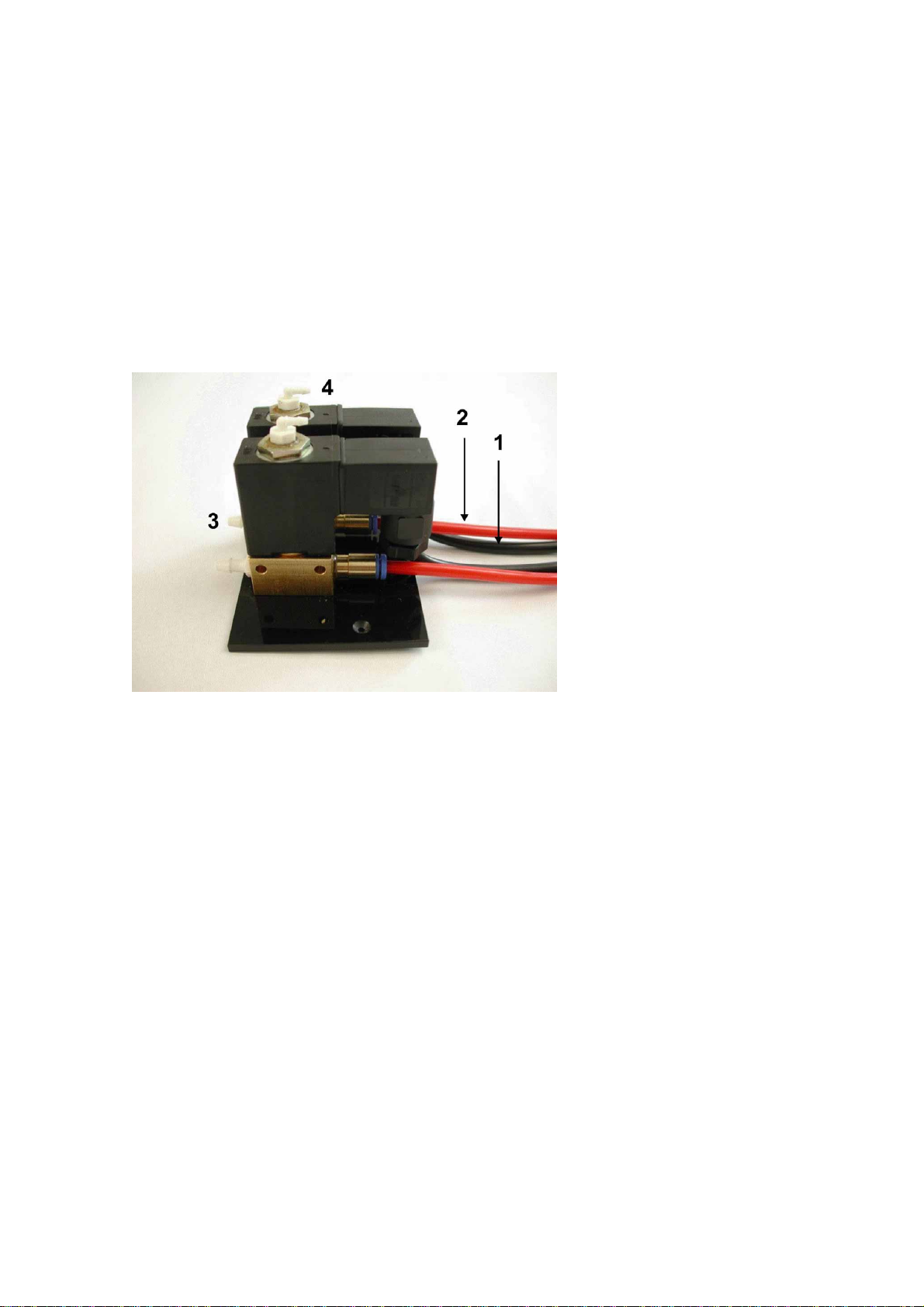
In order to speed up drug ejection, PDES-2DX systems are available with the microJect
option. These systems are equipped with a micro valve located in an injection holder. The
micro valve has a switch time of less than 1 ms and a very small volume that has to be
controlled, resulting in application times in the ms range.
The PDES-2DX is housed in a 19" cabinet that can be mounted in a rack. It comprises of two
channels. Two systems can be combined to form a 4 channel system. Each channel consists of
a precision pressure regulator, a digital pressure display, electronically controlled valves,
control electronics and a regulated power supply. Ejection of drugs can be activated manually
or via a TTL input. The operational status is indicated by a red/green LED. The pressure
output is monitored at a BNC output (1V / bar) and additionally the signal for pressure control
is available via TTL OUT BNC connector. Optionally, each channel can be equipped with an
"EXHAUST" coupling whereby a low "retain" pressure can be applied (analogous to the
"retaining" current used in iontophoretic systems).
Mode of operation and timing is selected by controls at the front panel. If the internal timers
are used, the eject time is preset by a control. Each channel can be turned off by using a
switch that is combined with the timing control. The operational status is indicated by a
red/green LED. Red means that the channel has been turned on and the valve is closed, green
indicates that the valve is open and injection takes place.
The remote control unit (option) is housed in a small box. For each channel it has a red LED
that indicates if the respective channel is turned on and a toggle switch with a temporary and a
fix position for starting drug application.
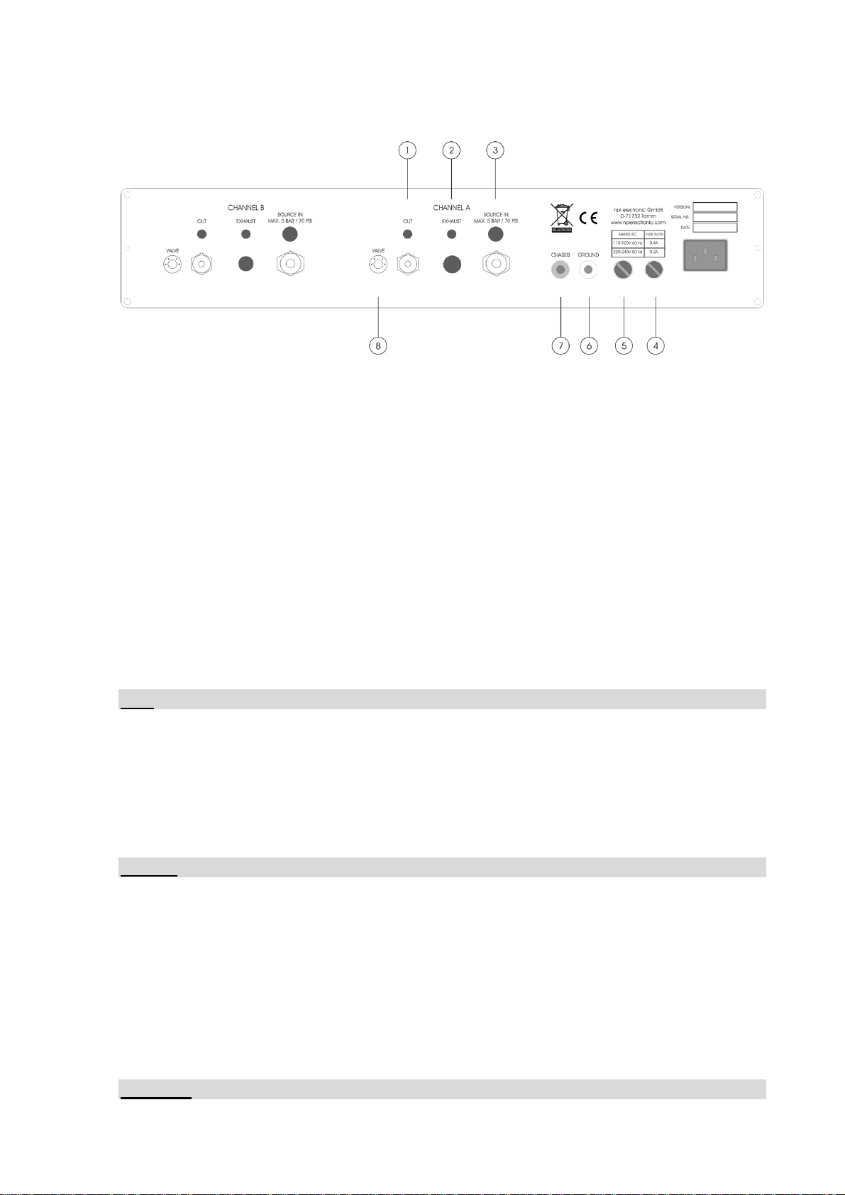
The pressure connectors (quick connect type) are located at the rear panel of the instrument.
Each channel is equipped with an INPUT coupling where the pressure source is connected, an
OUTPUT coupling where the injection pipette is connected, and optionally, an EXHAUST
coupling where a low "hold" pressure can be applied in order to avoid capillary effects at the
tip of the injection pipette or to apply a "retain" negative pressure (analogous to the
"retaining" current used in iontophoretic systems). The "retain" pressure must be generated by
an additional pneumatic device. Please contact npi electronic for details.
The injection pressure is preset by a precision pressure regulator. The pressure is displayed on
a digital manometer. Additional pneumatic devices (tubes, fittings connectors, filters etc.) are
available. Please contact npi electronic for details.
A calibration procedure allowing quantitative drug application is described by Hofmeier and
Lux (1981) (see chapter 3).

PDES-02DX-LA User Manual
___________________________________________________________________________
___________________________________________________________________________
version 1.3 page 5
2.2. Description of the Front Panel
Figure 1: PDES-2DX front panel view (the numbers are related to those in the text below)

PDES-02DX-LA User Manual
___________________________________________________________________________
___________________________________________________________________________
version 1.3 page 6
In the following description of the front panel elements, each element has a number that is
related to that in Figure 1. The number is followed by the name (in uppercase letters) written
on the front panel and the type of the element (in lowercase letters). Then, a short description
of the element is given. Since the front panel elements are identical for each channel (with
identical functions and labels) and therefore, are numbered and described only once (for
channel A).
(1) POWER push button
Push button to turn POWER on or off
(2) Pressure regulator
Rotary knob for regulating the pressure
(3) Manometer
Digital display for the pressure (X.XX bar or XXX.X psi)
(4) ON / EJECT LED
Indicates the operational status
red light: channel has been turned on, valve is closed
green light: valve is open or valve not connected
(5) TIME (ms) tumble-wheel switch
Five digit tumble-wheel switch to set the ejection time (XXXX.X ms) in TIMER mode
(6) START button
Push button to start operation. The START button can be used to start ejection in TIMER or
EXT. mode.
In TIMER mode pressing the START button opens the valve for the time set by #5.
In EXT. mode pressing the START button opens the valve as long as the button is pressed
(7) TTL INPUT connector
BNC connector for external operation
In TIMER mode a TTL HI ( +5V) signal opens the valve for the time set by #5.
In EXT. mode a TTL HI ( +5V) signal opens the valve as long as the signal level is HI
(8) TIMING MONITOR connector
BNC connector providing a TTL signal that indicates the status of the regulated injection
valve (HI = valve open, LO = valve closed)
(9) TIMER A, EXT., CONT. switch
Switch to set the operation mode (see also chapter 2.4)
(10) BAR / PSI switch
Switch to select the unit of the reading of the display (#3) and the output at PRESSURE
MONITOR (#11)
(11) PRESSURE MONITOR connector
BNC connector monitoring the pressure output, sensitivity: 1 V / bar or 0.1 V / psi,
respectively
(12) REMOTE CONTROL connector
Connector for the REMOTE CONTROL unit (see 2.5)

PDES-02DX-LA User Manual
___________________________________________________________________________
___________________________________________________________________________
version 1.3 page 7
2.3. Description of the Rear Panel
Figure 2: PDES-2DX rear panel view (the numbers are related to those in the text below)
The following connectors are located at the rear panel. The connectors are mentioned only for
CHANNEL A.
(1) OUT connector
Connector for connecting the injection micropipette or for connecting the pressure tubing of
the external valve on the remote valve plate. The EJECT pressure is supplied to this
connector.
(2) EXHAUST connector (optional)
Connector for connecting the HOLD pressure source. If no HOLD pressure is connected, the
system is exhausted as long as no pressure is applied to the pipette.
(3) SOURCE IN connector
Connector for connecting the filtered, dry and oil-free gas source (5 bar max.).
Note: npi recommends an input pressure of 1 bar more than the maximum output pressure.
(4) FUSE
Unplug the instrument when replacing the fuse or changing line voltage. Turn knob to open.
Replace fuse only with an appropriate specified type (see chapter 0)
(5) Voltage SELECTOR
Rotary switch for selecting the operating voltage (115 V / 230 V).
Caution: Always switch to the appropriate voltage before connecting the PDES to power.
(6) GROUND
This connector is linked to the internal system ground which has no connection to the 19"
cabinet (CHASSIS) and the mains ground to avoid ground loops.
(7) CHASSIS
This connector is linked to mains ground (green / yellow wire, protective earth).
(8) VALVE connector (optional)
Connector for the electrical connection of the VALVE located in a remote valve box or in the
microJECT.
Important: This connector is not used for systems without a remote valve or microJECT.

PDES-02DX-LA User Manual
___________________________________________________________________________
___________________________________________________________________________
version 1.3 page 8
2.4. External Valves
External valve(s) for the PDES system are either mounted on a remote valve plate or in the
microJECT micro valve pipette holder.
Remote Valve Plate
The valves which are controlled by the PDES-02DX are located on the remote valve plate
(see Figure 3). Tubing and cable of the external valves are connected at the rear panel of the
PDES system (refer to chapter 2.3). Exhaust is usually not connected.
Figure 3: external valves on remote valve plate
1: electrical connection (black)
2: EJECT pressure tubing (red)
3: connector for ejection pipette
4: exhaust connector (optional)

PDES-02DX-LA User Manual
___________________________________________________________________________
___________________________________________________________________________
version 1.3 page 9
microJECT micro Valve Pipette Holder
The valve which is controlled by the PDES-02DX is located in the micro valve pipette holder,
called microJECT (see Figure 4). Tubing and cable of the microJECT are connected at the
rear panel of the PDES system (refer to chapter 2.3). Exhaust is usually not connected.
Figure 4: microJECT
1: pipette connector
2: connector for EJECT pressure
3: connector for EXHAUST pressure (optional)
4: electrical connection
Important: In experiments with high pressures (> 1 bar) it might be necessary to insert 2 seals
into the pipette connector in order to prevent the pipette from moving.
Figure 5: microJECT – pipette insertion
Caution: Pipettes that are not rigidly fixed in the pipette connector might be pressed out of
the connector by high pressure. Always adhere to the appropriate safety measures.

PDES-02DX-LA User Manual
___________________________________________________________________________
___________________________________________________________________________
version 1.3 page 10
2.5. Operation
o Connect the gas source to the SOURCE IN connector at the rear panel. The gas source
must be clean and filtered by a 5 µm filter element.
Important: Do not connect sources of OXYGEN or COMBUSTIBLE or EXPLOSIVE
gases!!
o Connect the microJECT holders to the OUT connectors and VALVE connectors at the
rear panel.
o Connect your ejection pipettes to the microJECTs (#1, Figure 3).
o Turn on pressure and adjust the EJECTION pressure to the desired value using the
pressure regulator.
o Connect a digital timing unit to the TTL INPUT BNC connector at the front panel.
o For remote operation connect the remote control unit (option) to the REMOTE
CONTROL connector.
o Turn channel on (TIMER control).
o The LED is red when no ejection happens, and green when the pressure is applied to the
pipette.
o Select the operation mode using the respective toggle switch at the front panel (see Figure
1).
In the CONT. position the application can be controlled manually, i.e. as long as
the CONT. position is set pressure is applied to the pipette.
In the EXT. position the duration of the application is determined directly by the
duration of the TTL pulse.
In the TIMER position the duration is preset by the timer control and time base of
the PDES.
o Use the START button to test the system. The START button can be used to start ejection
in TIMER or EXT. mode. In TIMER mode pushing the START button starts ejection for
the time set by the timer control (#5, Figure 1). In EXT. mode ejection lasts as long as the
START button is pushed.

PDES-02DX-LA User Manual
___________________________________________________________________________
___________________________________________________________________________
version 1.3 page 11
o REMOTE CONTROL (option): The selected operation mode (at the controller)
determines the way the REMOTE CONTROL works.
In the CONT. mode the remote control unit is disabled.
In the EXTERN mode the valve is open as long the REMOTE control switch is
activated (CONT./TIMED = continuous, START = temporarily).
In the TIMER mode the internal timer is triggered once by activation of the
REMOTE control switch (CONT./TIMED or START). The green LED indicates
which channel has been turned on.
Figure 6: PDES remote control (optional)
Note: Green LED indicates that the valve is not connected properly or continuous operation.
o REMOTE CONTROL with foot switch (option, see Figure 7): The selected operation
mode (at the controller) determines the way the REMOTE CONTROL footswitch works.
In the CONT. mode the remote control unit is disabled.
In the EXTERN mode the valve is open as long the REMOTE control foot switch is
activated.
In the TIMER mode the internal timer is triggered once by activation of the
REMOTE control foot switch
Figure 7: PDES remote control footswitch as 2-channel or single channel version.

PDES-02DX-LA User Manual
___________________________________________________________________________
___________________________________________________________________________
version 1.3 page 12
Figure 8: operation modes of the PDES-2DX

PDES-02DX-LA User Manual
___________________________________________________________________________
___________________________________________________________________________
version 1.3 page 13
3. Literature
General Methods
o Hahnel, C. (1992) Quantitative Microinjection, in: H. Kettenmann and R. Grantyn (eds.)
Practical Electrophysiological methods, Wiley-Liss, New York.
o Hofmeier G, Lux HD (1981) The time course of intracellular free calcium and related
electrical effects after injection of CaCl2into neurons of the snail, Helix pomatia Pflügers
Arch. 391:242-251.
o Lalley, P.M. (1999) Microiontophoresis and Pressure Ejection, in: U. Windhorst, and H.
Johansson (eds) Modern Techniques in Neuroscience Research, Springer, Berlin
Heidelberg, New York.
o Misgeld, U (1992) Droplet application of Agonists, in: H. Kettenmann and R. Grantyn
(eds.) Practical Electrophysiological methods, Wiley-Liss, New York.
General
o Bickmeyer, U., Heine, M., Manzke, T., & Richter, D. W. (2002). Differential modulation
of Ih by 5-HT receptors in mouse CA1 hippocampal neurons. Eur.J.Neurosci. 16, 209-218.
o Eggermann, E. & Feldmeyer, D. (2009). Cholinergic filtering in the recurrent excitatory
microcircuit of cortical layer 4. Proc.Natl.Acad.Sci.U.S.A. 106, 11753-11758.
o Garaschuk, O., Milos, R. I., & Konnerth, A. (2006). Targeted bulk-loading of fluorescent
indicators for two-photon brain imaging in vivo. Nat.Protocols 1, 380-386.
o Guzman, J. N., Hernandez, A., Galarraga, E., Tapia, D., Laville, A., Vergara, R., Aceves,
J., & Bargas, J. (2003). Dopaminergic modulation of axon collaterals interconnecting spiny
neurons of the rat striatum. J Neurosci. 23, 8931-8940.
o Hanganu, I. L. & Luhmann, H. J. (2004). Functional Nicotinic Acetylcholine Receptors on
Subplate Neurons in Neonatal Rat Somatosensory Cortex. Journal of Neurophysiology 92,
189-198.
o Kilb, W., Hanganu, I. L., Okabe, A., Sava, B. A., Shimizu-Okabe, C., Fukuda, A., &
Luhmann, H. J. (2008). Glycine receptors mediate excitation of subplate neurons in
neonatal rat cerebral cortex. J.Neurophysiol. 100, 698-707.
o Kolbaev, S. & Draguhn, A. (2008). Glutamine-induced membrane currents in cultured rat
hippocampal neurons. Eur.J Neurosci. 28, 535-545.
o Langer, J. & Rose, C. R. (2009). Synaptically induced sodium signals in hippocampal
astrocytes in situ. J Physiol. 587, 5859-5877.
o Lin, B. J., Chen, T. W., & Schild, D. (2007). Cell type-specific relationships between
spiking and [Ca2+]i in neurons of the Xenopus tadpole olfactory bulb. Journal of
Physiology 582, 163-175.
o Marandi, N., Konnerth, A., & Garaschuk, O. (2002). Two-photon chloride imaging in
neurons of brain slices. Pflugers Arch. 445, 357-365.
o Partridge, L.D., H.U. Zeilhofer and D. Swandulla (1998) Combined Whole-Cell and
Single-Channel Current Measurement with Quantitative Ca2+ Injection or Fura-2
Measurement of Ca2+, in P.M. Conn (Ed.) Ion Channels Part B, Methods in Enzymology
Vol. 293, Academic Press SanDiego.

PDES-02DX-LA User Manual
___________________________________________________________________________
___________________________________________________________________________
version 1.3 page 14
o Ponimaskin, E., Dumuis, A., Gaven, F., Barthet, G., Heine, M., Glebov, K., Richter, D. W.,
& Oppermann, M. (2005). Palmitoylation of the 5-Hydroxytryptamine4a Receptor
Regulates Receptor Phosphorylation, Desensitization, and {beta}-Arrestin-Mediated
Endocytosis. Molecular Pharmacology 67, 1434-1443.
o Qiu, J., Yao, S., Hindmarch, C., Antunes, V., Paton, J., & Murphy, D. (2007).
Transcription factor expression in the hypothalamo-neurohypophyseal system of the
dehydrated rat: upregulation of gonadotrophin inducible transcription factor 1 mRNA is
mediated by cAMP-dependent protein kinase A. J Neurosci. 27, 2196-2203.
o Stepanyan, R. & Frolenkov, G. I. (2009). Fast adaptation and Ca2+ sensitivity of the
mechanotransducer require myosin-XVa in inner but not outer cochlear hair cells. Journal
of Neuroscience 29, 4023-4034.
o Wolfram, V. & Juusola, M. (2004). The Impact of Rearing Conditions and Short-Term
Light Exposure on Signaling Performance in Drosophila Photoreceptors. Journal of
Neurophysiology 92, 1918-1927.
Microinjection into Oocytes
o Wetzel, C. H., Oles, M., Wellerdieck, C., Kuczkowiak, M., Gisselmann, G., & Hatt, H.
(1999). Specificity and sensitivity of a human olfactory receptor functionally expressed in
human embryonic kidney 293 cells and Xenopus Laevis oocytes. J.Neurosci. 19, 7426-
7433.
Fast drug application with microJECT (EHM)
o Courjaret, R., Troger, M., & Deitmer, J. W. (2009). Suppression of GABA input by A1
adenosine receptor activation in rat cerebellar granule cells. Neuroscience. 162, 946-958.
o Heck, N., Kilb, W., Reiprich, P., Kubota, H., Furukawa, T., Fukuda, A., & Luhmann, H. J.
(2007). GABA-A receptors regulate neocortical neuronal migration in vitro and in vivo.
Cereb Cortex. 17, 138-148.

PDES-02DX-LA User Manual
___________________________________________________________________________
___________________________________________________________________________
version 1.3 page 15
4. Technical Data
Source gas:
air, nitrogen, helium etc. no aggressive, combustible or explosive gases, filtered by a 5 µm
filter element.
Pressure range:
input pressure: max. 5 bar (1 bar = 105Pa = 14.5 psi)
pressure control range: 0-2 bar, 0-29 psi or 0-4 bar, 0-58 psi
Input and output couplings:
quick connect type
Tubes:
input: 6 mm OD
output: 4 mm OD
Status / EJECT time indicator:
red/green LED
red light: channel has been turned on, valve is closed
green light: valve is open or valve not connected
Mode selection:
three position toggle switch, (TIMER, CONT., EXT.)
Minimum valve switch time:
standard valve: approx. 10 ms
microJECT: <1 ms
Digital timer:
100 µs – 9.9 s set by five digit tumble-wheel switch (0000.0-9999.9)
Pulse input:
standard BNC connector, TTL (LO = 0-2.5 V, HI = 2.5-12 V), input impedance 10 k
Pulse output:
PRESSURE MONITOR: standard BNC connector, sensitivity: 1 V / bar or 0.1 V / psi,
output impedance 249
TIMING MONITOR: standard BNC connector, TTL (LO = +0-1 V, HI = +5 V), output
impedance 249
Dimensions:
19” rackmount cabinet, 19” (483 mm), 10” (250 mm), 3.5” (88 mm)
Power requirements:
115/230 V AC, 20-40 W, Fuse: 0.2A / 230V; 0.4 A / 115V
Remote control (option):
Manual: Toggle switch and status LED for each channel, size 2.5x4x10 cm
Footswitch: size: 6,5 x 9 x 2.5 cm (one channel), 20 x 14 x 4 cm (two channels)
Table of contents
Other NPI Laboratory Equipment manuals
Popular Laboratory Equipment manuals by other brands

PolyScience
PolyScience WBE10A11B Operator's manual

Lumencor
Lumencor SPECTRA III (L) Light Engine instruction manual

Glas-Col
Glas-Col FlexiVap 109A YH-1/YH-1-HF Operating and safety instructions

Qiagen
Qiagen BioRobot M48 user manual

VWR
VWR 5600 Series Operating and maintenance manual

TSI Instruments
TSI Instruments AeroTrak+ quick start guide