Haag-Streit BP 900 User manual

1
DEUTSCHENGLISH FRANÇAIS ITALIANO ESPAÑOL NEDERLANDS
PORTUGUÊS SVENSKA
DEUTSCHENGLISHFRANÇAISITALIANOESPAÑOLNEDERLANDS PORTUGUÊS
SVENSKA
© HAAG‑STREIT AG, 3098 Koeniz, Switzerland ‑ HS‑Doc. no. 1500.7220590‑04090 – 2021 – 08
INSTRUCTIONS FOR USE
Slit lamp
BP 900¨
9. Edition / 2021 – 08

2
DEUTSCHENGLISH FRANÇAIS ITALIANO ESPAÑOL NEDERLANDS
PORTUGUÊS SVENSKA
© HAAG‑STREIT AG, 3098 Koeniz, Switzerland ‑ HS‑Doc. no. 1500.7220590‑04090 – 2021 – 08
INSTRUCTIONS FOR USE
Slit lamp
BP 900¨
9. Edition / 2021 – 08
Preface
Thank you for choosing a Haag-Streit device. Provided you comply carefully with the
regulations in these instructions for use, we can guarantee reliable and trouble-free
use of our product.
WARNING!
Read the instruction manual carefully before commissioning this product.
It contains important information regarding the safety of the user and
patient.
NOTE!
For USA only: Federal law restricts this device to sale by or on the order
of a physician or licensed practitioner.
WARNING!
This device is equipped with high intensity light emitting diodes.
Excessive exposure of patients in treatment with certain medication may
lead to phototoxic adverse reactions, due to higher photosensitivity.

3
DEUTSCHENGLISH FRANÇAIS ITALIANO ESPAÑOL NEDERLANDS
PORTUGUÊS SVENSKA
DEUTSCHENGLISHFRANÇAISITALIANOESPAÑOLNEDERLANDS PORTUGUÊS
SVENSKA
© HAAG‑STREIT AG, 3098 Koeniz, Switzerland ‑ HS‑Doc. no. 1500.7220590‑04090 – 2021 – 08
Contents
¥ 1 Safety...................................................................................................................................................4
◦ 1.1 Comments on these instructions for use........................................................................................4
◦ 1.2 Ambient conditions.........................................................................................................................4
◦ 1.3 Shipment and unpacking ...............................................................................................................4
◦ 1.4 Installation warnings ......................................................................................................................4
◦ 1.5 Operation, environment .................................................................................................................5
◦ 1.6 Light toxicity ...................................................................................................................................5
◦ 1.7 Disinfection ....................................................................................................................................5
◦ 1.8 Warranty and product liability ........................................................................................................6
◦ 1.9 Reporting obligation.......................................................................................................................6
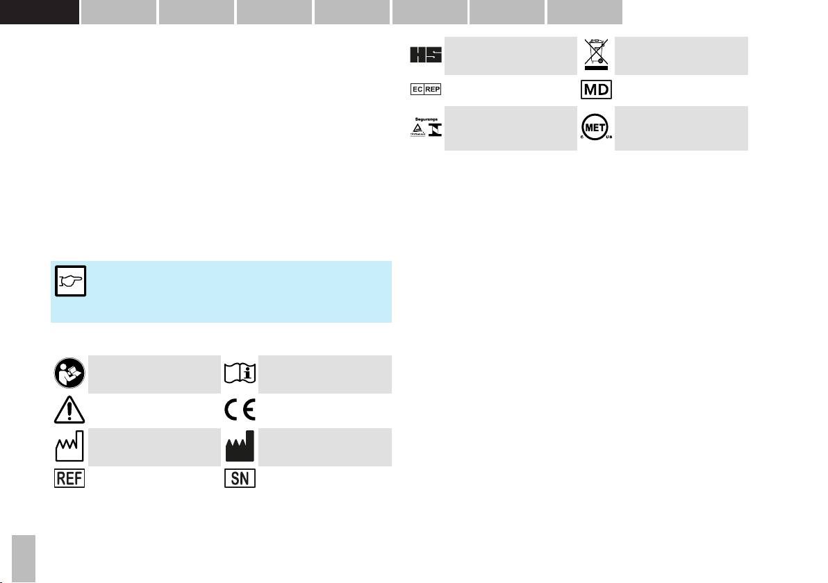
◦ 1.10 Description of symbols.................................................................................................................6
¥ 2 Intended purpose / intended use .......................................................................................6
◦ 2.1 Device description..........................................................................................................................6
▪ 2.1.1 Intended users....................................................................................................................7
◦ 2.2 Medical purpose.............................................................................................................................7
▪ 2.2.1 Indications...........................................................................................................................7
▪ 2.2.2 Part of the body ..................................................................................................................7
▪ 2.2.3 Patient population...............................................................................................................7
▪ 2.2.4 Contraindications................................................................................................................7
◦ 2.3 Principles of operation ...................................................................................................................7
▪ 2.3.1 Operating environment .......................................................................................................7
◦ 2.4 Clinical benefit................................................................................................................................7
¥ 3 Introduction .....................................................................................................................................8
◦ 3.1 Overview........................................................................................................................................8
¥ 4 Device assembly / installation .............................................................................................9
◦ 4.1 Microscope and illumination...........................................................................................................9
◦ 4.2 Power supply .................................................................................................................................9
◦ 4.3 Instrument base with weight compensation facility........................................................................9
◦ 4.4 Setting the weight compensation facility........................................................................................9
◦ 4.5 Switching on the compensation facility ..........................................................................................9
◦ 4.6 Switching off the compensation facility ..........................................................................................9
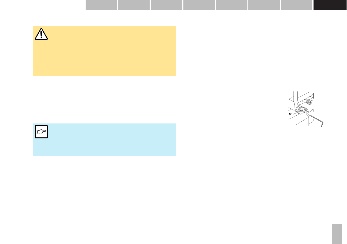
◦ 4.7 Regulating the clearance of the slit width controls.........................................................................9
¥ 5 Commissioning .............................................................................................................................9
◦ 5.1 Switching on the device .................................................................................................................9
¥ 6 Operation.........................................................................................................................................10
◦ 6.1 Setting the eyepieces...................................................................................................................10
◦ 6.2 Preparing the patient....................................................................................................................10
◦ 6.3 Operating the device....................................................................................................................10
◦ 6.4 Setting the filters & diaphragms...................................................................................................12
◦ 6.5 Fixation star .................................................................................................................................12
◦ 6.6 Microscope and eyepiece ............................................................................................................12
¥ 7 Decommissioning ..................................................................................................................... 12
¥ 8 Technical data ............................................................................................................................. 13
◦ 8.1 Slit illumination............................................................................................................................. 13
◦ 8.2 Stereo microscope....................................................................................................................... 13
◦ 8.3 Instrument base........................................................................................................................... 13
◦ 8.4 Dimensions.................................................................................................................................. 13
¥ 9 Maintenance.................................................................................................................................. 13
◦ 9.1 Device inspection ........................................................................................................................ 13
◦ 9.2 Servicing...................................................................................................................................... 14
◦ 9.3 Cleaning and disinfection ............................................................................................................14
◦ 9.4 Replacing the illumination mirror .................................................................................................14
◦ 9.5 Dust cover ................................................................................................................................... 14
¥ 10 Appendix ...................................................................................................................................... 14
◦ 10.1 Accessories / functionals parts / detachable parts / consumables ............................................15
◦ 10.2 Legal regulations .......................................................................................................................15
◦ 10.3 Classification ............................................................................................................................. 15
◦ 10.4 Disposal..................................................................................................................................... 15
◦ 10.5 Observed standards ..................................................................................................................15
◦ 10.6 Information and manufacturer's declaration concerning electromagnetic compatibility (EMC) .16
▪ 10.6.1 General........................................................................................................................... 16
▪ 10.6.2 Emitted interference .......................................................................................................16
▪ 10.6.3 Electromagnetic immunity environment tested (part 1).................................................. 17
▪ 10.6.4 Electromagnetic immunity environment tested (part 2).................................................. 18
▪ 10.6.5 Recommended separation distances between portable and mobile RF communications
equipment and this product....................................................................................................... 20

4
DEUTSCHENGLISH FRANÇAIS ITALIANO ESPAÑOL NEDERLANDS
PORTUGUÊS SVENSKA
© HAAG‑STREIT AG, 3098 Koeniz, Switzerland ‑ HS‑Doc. no. 1500.7220590‑04090 – 2021 – 08
1Safety
DANGER!
Failure to comply with these instructions may result in material damage
or pose a danger to patients or users.
WARNING!
These warnings must absolutely be complied with to guarantee safe
operation of the product and to avoid any danger to users and to
patients.
NOTE!
Important information, please read carefully.
1.1 Comments on these instructions for use
NOTE!
In these instructions for use the point is used as decimal separator.
1.2 Ambient conditions
Temperature −40 °C ... +70 °C
Air pressure 500 hPa ... 1060 hPa
Transport
Relative humidity 10 % ... 95 %
Temperature −10 °C ... +55 °C
Air pressure 700 hPa ... 1060 hPa
Storage
Relative humidity 10 % ... 95 %
Temperature +10 °C ... +35 °C
Air pressure 800 hPa ... 1060 hPa
Use
Relative humidity 30 % ... 90 %
1.3 Shipment and unpacking
• Before unpacking the device, check whether the packaging shows traces of
improper handling or damage. If this is the case, notify the transport company
that delivered the goods to you.
• Unpack the device together with a representative of the transport company.
Make a report of any damaged parts. This report must be signed by you and by
the representative of the transport company.
• Leave the device in the packaging for a few hours before unpacking it
(condensation).
• Check the device for damage after it is unpacked.
• Return defective devices in the appropriate packaging.
• Store packaging material carefully so that it can be used for potential returns or
when moving.
• The slit lamp and headrest must be installed on an electrically insulated,
fireproof table top.
• The rail covers (a) prevent the slit lamp from tilting.
• Check that the connection parts of the accessories are in the correct position
(screw connections, quick-release fasteners).
1.4 Installation warnings
WARNING!
•Do not modify this device without authorization of the manufacturer.
Installation and repairs may only be performed by trained
specialists.
• Any third-party device must be connected in compliance with the EN
60601-1 standard.
• Only original Haag-Streit spare parts may be used.

5
DEUTSCHENGLISH FRANÇAIS ITALIANO ESPAÑOL NEDERLANDS
PORTUGUÊS SVENSKA
DEUTSCHENGLISHFRANÇAISITALIANOESPAÑOLNEDERLANDS PORTUGUÊS
SVENSKA
© HAAG‑STREIT AG, 3098 Koeniz, Switzerland ‑ HS‑Doc. no. 1500.7220590‑04090 – 2021 – 08
• Use of this device adjacent to or stacked with other equipment
should be avoided because it could result in improper operation. If
such use is necessary, this device and the other equipment should
be observed to verify that they are operating normally.
• Grounding reliability can only be achieved when unit is connected to
a hospital grade receptacle. (Not valid for EU countries).
• The device should be set up in such a way that the plug is always
easily accessible and the device can easily be disconnected from
the mains.
1.5 Operation, environment
DANGER!
Never use the device in potentially explosive environments where
volatile solvents (alcohol, petrol, etc.) and flammable anaesthetics are in
use.
WARNING!
• The device must be switched off after every use. Otherwise there is
a risk of overheating when a protective dust cover is used.
• This device must not be operated near of high frequency surgical
equipment and the radio frequency shielded room of a medical
electrical system for magnetic resonance imaging, where the
intensity of electromagnetic disturbances is high.
• Portable radio frequency communications equipment (including
peripherals such as antenna cables and external antennas) should
be used no closer than 30 cm (12 inches) to any part of the device,
including cables specified by Haag-Streit. Otherwise, degradation of
the performance of this device could result.
NOTE!
• This device must only be operated by qualified personnel. The
owner is responsible for their training.
• This device may only be used in accordance with the instructions in
the 'Intended purpose / intended use' chapter.
1.6 Light toxicity
WARNING!
• The light from this device may be dangerous. The risk of eye
damage increases with the exposure time. An exposure time with
this device at maximum intensity of longer than 131 seconds
exceeds the guideline value for a risk.
• As extended, intensive illumination can damage the retina, the use
of the device in the examination of the eye should not be prolonged
unnecessarily. The illumination of this slit lamp emits a radiation in
the range between 400 and 750 nm. Detailed information on the
radiation can be provided on request.
• The retinal dose for a photochemical risk is composed of the product
of the radiance and the exposure time. If the radiance is halved, the
time until the exposure time limit value is reached will double
accordingly. To date, no acute, optical radiation hazard has been
detected in slit lamps. Nevertheless, we recommend keeping the
intensity of the light reaching the patient's retina to the minimum
possible for the respective diagnosis. Children, people with aphakia
and people suffering from eye conditions are most at risk. An
increased risk may also occur if the retina is exposed to the same or
a similar device with a visible light source within 24 hours. This
applies, in particular, if the retina has been photographed with a
flashbulb in advance.
1.7 Disinfection
NOTE!
The device can, but does not need to be disinfected. For more
information, please refer to the 'Maintenance' chapter.

6
DEUTSCHENGLISH FRANÇAIS ITALIANO ESPAÑOL NEDERLANDS
PORTUGUÊS SVENSKA
© HAAG‑STREIT AG, 3098 Koeniz, Switzerland ‑ HS‑Doc. no. 1500.7220590‑04090 – 2021 – 08
1.8 Warranty and product liability
• Haag-Streit products must be used only for the purposes and in the manner
described in the documents distributed with the product.
• The product must be treated as described in the ‘Safety’ chapter. Improper
handling can damage the product. This would void all guarantee claims.
• Continued use of a product damaged by incorrect handling may lead to personal
injury. In such a case, the manufacturer will not accept any liability.
• Haag-Streit does not grant any warranties, either expressed or implied, including
implied warranties of merchantability or fitness for a particular use.
• Haag-Streit expressly disclaims liability for incidental or consequential damage
resulting from the use of the product.
• This product is covered by a limited warranty granted by your seller.
• For USA only: This product is covered by a limited warranty, which may be
reviewed at www.haag-streit-usa.com.
1.9 Reporting obligation
NOTE!
Any serious incident that has occurred in relation to the device must be
reported to Haag-Streit and the competent authority of the Member
State in your country.
1.10 Description of symbols
Follow instruction for use Read the instructions for use
attentively
General warning, read the
accompanying documentation
European certificate of
conformity
Date of manufacture Manufacturer
Haag-Streit reference number Serial number
Trademark of the manufacturer
Haag-Streit AG
Notes on disposal, see the
'Disposal' chapter
Listed European Authorized
Representative Medical Device
Testsymbol of TÜV Rheinland
with approval for INMETRO
Brasil
MET Listed Mark with approval
for USA and Canada
2Intended purpose / intended use
A slit lamp biomicroscope is intended for use in eye examination. It is used to aid in
the diagnosis and documentation of diseases or trauma which affect the structural
properties of the eye.
2.1 Device description
The devices of the slit lamp are made up of:
• Stereo biomicroscope
• Slit illumination
• Instrument base
• Headrest and chin rest
The illumination system and a biomicroscope are mounted to an instrument base
operated by joystick. The single joystick allows horizontal and vertical displacement
of the slit lamp across the examination table. Both elements, the illumination system
and the biomicroscope, can be swiveled progressively across the pivot,
independently of one another.
A sturdy headrest is attached to the table. Both the table and the chin rest are
adjustable in height to provide a comfortable, yet sturdy examination position to the
patient, outside of the device's range of motion. As this device operates non-
invasively it only comes into contact with the patient at the chin rest and forehead
band.

7
DEUTSCHENGLISH FRANÇAIS ITALIANO ESPAÑOL NEDERLANDS
PORTUGUÊS SVENSKA
DEUTSCHENGLISHFRANÇAISITALIANOESPAÑOLNEDERLANDS PORTUGUÊS
SVENSKA
© HAAG‑STREIT AG, 3098 Koeniz, Switzerland ‑ HS‑Doc. no. 1500.7220590‑04090 – 2021 – 08
2.1.1 Intended users
Users are qualified medical professionals such as ophthalmologists, optometrists,
opticians, nurses and researchers or other qualified specialists as permitted by local
legislation.
2.2 Medical purpose
This device has the following medical purpose:
•Diagnosis and monitoring of diseases of the anterior segment of the eye
•Diagnosis and monitoring of injuries of the anterior segment of the eye
• Investigation of the anatomy and physiological or pathological state of the
anterior segment of the eye
2.2.1 Indications
The use of the slit lamp is indicated for the following medical conditions:
• Local and systemic diseases affecting the eye
• Lesions and defects of the anterior segment
• Acute infections and inflammations
• Presence of intraocular foreign bodies
• Other traumata of the eye
2.2.2 Part of the body
The slit lamp is intended for the examination of the human eye, specifically the
anterior segment of the eye (i.e., lids, lashes, conjunctiva, cornea, anterior chamber,
iris, and lens).
2.2.3 Patient population
This device is intended for use on human patients with the physical ability to sit in
front of a slit lamp with their head resting against the headrest in a steady position
and the mental ability to follow instructions.
2.2.4 Contraindications
There are no known contraindications.
2.3 Principles of operation
• The slit lamp implements the principle of focal illumination: The focal point of the
microscope and the illumination coincide.
• The microscope arm and the illumination arm are mounted on an instrument
base: Both can be swivelled independently around the same vertical axis.
• The instrument base can be moved in all three axes.
• When illuminating transparent media with a narrow, sharp slit, an 'optical
section' can be magnified and viewed through the microscope.
• The patient's head is fixed to a height-adjustable headrest holder so that the
examination can be carried out quickly and as comfortably as possible for both
doctor and patient.
2.3.1 Operating environment
The slit lamp is intended to be used in professional health care facilities such as
hospitals, physician's, optometrist's and optician's practices. For optimal use of the
slit lamp, the ambient lighting should be attenuated to improve image contrast. In
case of transillumination of the iris or for viewing details at great magnification at a
narrow slit, it may be necessary to completely darken the room.
2.4 Clinical benefit
The use of the slit lamp allows for the systematic examination of the eye under
magnification, thus permitting the diagnoses of pathologies that may have otherwise
remained unidentified and could have lead to blindness if left untreated.
The clinical benefits of the product outweigh the remaining residual risks to the
patient.

8
DEUTSCHENGLISH FRANÇAIS ITALIANO ESPAÑOL NEDERLANDS
PORTUGUÊS SVENSKA
© HAAG‑STREIT AG, 3098 Koeniz, Switzerland ‑ HS‑Doc. no. 1500.7220590‑04090 – 2021 – 08
3Introduction
The slit lamp consists of an illumination and a binocular microscope. The instrument
base can be used to move the entire device in front of the eyes. The illumination
offers a large number of setting options to make the practically invisible areas in the
eye visible. There is also a range of accessories available for the slit lamp to allow
special diagnosis possibilities in addition to the general examinations.
3.1 Overview
1. Lamp cable
2. Headrest
3. Headband
4. Height mark on headrest (patient
eye)
5. Adjustable fixation lamp
6. Chin rest
7. Height adjustment of chin rest
8. LED illumination LI 900, see
separate manual
9. Background illumination (fixed)
10. Lever for filters
11. Scale for angled position of the slit
image (5° increments)
12. Background illumination with
swivel bracket
13. Illumination mirror
14. Diffusor
15. Magnification changer
16. Mounting screw for the stereo
microscope
17. Slot for accessories (test rod,
background illumination, etc.)
18. Centring screw
19. Illumination unit / microscope
angle scale
20. Illumination arm locking screw
21. Slit width controls
22. Microscope arm locking screw
23. Cross slides
24. Rail cover
25. Illumination control 'on table'
26. Illumination control 'in table'
27. Slit length / diaphragm scale
28. Slit length, slit rotation, blue filter
and fixation star control
29. Cover screw for accessories pin
30. Quick-release fastener for
accessories
31. Stereo microscope
32. Eyepieces
33. Thread for fixing the tonometer AT
900 mod. BP or tonometer AT 900
D mod. BP
34. Mounting screw for breath shield
35. Breath shield
36. Inclination angle latch 5 – 20°
37. Joy stick base locking screw
38. Axle
39. Control lever
40. Slide plate

9
DEUTSCHENGLISH FRANÇAIS ITALIANO ESPAÑOL NEDERLANDS
PORTUGUÊS SVENSKA
DEUTSCHENGLISHFRANÇAISITALIANOESPAÑOLNEDERLANDS PORTUGUÊS
SVENSKA
© HAAG‑STREIT AG, 3098 Koeniz, Switzerland ‑ HS‑Doc. no. 1500.7220590‑04090 – 2021 – 08
4 Device assembly / installation
WARNING!
•Do not modify this device without authorization of the manufacturer.
Installation and repairs may only be performed by trained
specialists.
• Contact your Haag-Streit representative for installation, repairs and
modification work on the system. The contact details are available at
www.haag-streit.com.
• Only original Haag-Streit spare parts may be used.
4.1 Microscope and illumination
• The slit lamp is packaged and delivered fully assembled. The transport safety
devices must be removed prior to commissioning.
• Fix the breath shield (35) in place by fastening the knurled screw (34) on the
inside of the bearer arm.
4.2 Power supply
NOTE!
• Observe the respective Haag-Streit instructions for use. For further
information, please contact your Haag-Streit representative.
•This device must only be operated with PS-LED and PS-LED HSM
901 Haag-Streit power supplies and the RM02 release module.
4.3 Instrument base with weight compensation facility
The weight of additional accessories mounted on the microscope can be
compensated using counterbalance springs. This keeps the height adjustment of the
slit lamp easy.
4.4 Setting the weight compensation facility
Turn the control lever (60) to its lowest position and then loosen it slightly a quarter
turn. Turn the microscope and illumination to the side. Apply 1−3 springs depending
on the accessory.
4.5 Switching on the compensation facility
Turn anticlockwise until the screws (59) are completely released.
4.6 Switching off the compensation facility
Turn clockwise until you meet resistance. Verify whether the microscope arm
springs back downwards if you push it upwards with your hand. This will only
happen if the load is already at maximum. Generally, as many counterbalance
springs should be deactivated as necessary until this spring action occurs. The
weight compensation facility is set correctly once the illumination and microscope
with the mounted accessories weigh slightly more than the counterbalance springs.
4.7 Regulating the clearance of the slit width controls
The small screw in the centre of the right control knob
(83) allows you to regulate the friction of the turning
movement of these adjusting knobs. Turning it slightly
to the right (in) makes it harder, turning it left (out)
makes it easier. It should at least be set so hard that
the slit cannot close on its own.
5 Commissioning
The device can be switched on and off using the mains power switch on the power
supply. The green lamp in the rocker switch lights up when the device is switched
on.
5.1 Switching on the device
• Connect the power supply to the mains and press the rocker switch. The green
lamp in the rocker switch lights up when the device is switched on.
• Turn the rotating knob on the illumination control to a position between '1' and
'10'.

10
DEUTSCHENGLISH FRANÇAIS ITALIANO ESPAÑOL NEDERLANDS
PORTUGUÊS SVENSKA
© HAAG‑STREIT AG, 3098 Koeniz, Switzerland ‑ HS‑Doc. no. 1500.7220590‑04090 – 2021 – 08
6Operation
6.1 Setting the eyepieces
NOTE!
The eyepieces must be individually set prior to the first examination in
accordance with the refraction of the examiner. Insert the provided focus
test rod (41) in place of the protective cover (42) and turn its black
projection surface at a right angle to the microscope axis. Return the
illumination and microscope to the central position (0°).
41. Test rod
42. Protective cover
43. Sliding occluders
41
42
43
• Each eyepiece should be set individually by turning the knurled ocular refraction
ring with dioptre scale until the projected slit can be seen in focus. The setting is
performed from the (+) to the (-) side at low magnification.
• The required pupil distance should then be set on the microscope.
• The sliding occluders (43) are used to set the correct working distance for the
examiner from the eyepiece.
• Examiners who do not wear glasses: Pull the occluders out as far as they will
go.
• Examiners who do wear glasses: Push the occluders in as far as they will go.
6.2 Preparing the patient
• In order to attain a solid basis for the forehead and chin to rest on, the table
height should be selected such that the patient sits bent over forward.
• To ensure that only the part of the eye being examined is illuminated, the slit
height should be set accordingly in order to avoid distracting streaking of light.
• Applied parts which come into contact with the patient (headrest) should be
disinfected prior to every use (see instructions for use 'Headrest').
• The slit lamp must be switched off after every examination in accordance with
the 'Decommissioning' chapter.
6.3 Operating the device
WARNING!
The device must be switched off after every use. Otherwise there is a
risk of overheating when a protective dust cover is employed.
• Use the turn screw (7) to set the chin rest (6) in such a way that the patient’s
eyes are at the same height as the black mark (4) on the sides of the headrest.
• Adjust the eyepieces (32) in accordance with the examiner’s refraction by
turning the knurled rings and set the eye distance.
• Switch on the illumination by turning the switch on the power supply.
• Adjust the height of the slit lamp by turning the control lever (39) until the light
beam and microscope axis are at eye level.
• The magnification of the stereo microscope is changed using the magnification
changer (15).
• The rigid control lever (40) gently inclined towards the examiner can be used to
push the entire device until the slit appears approximately focused on the
cornea. This initial setting is verified with the naked eye. Fine tuning is
performed by tilting the control lever while observing via the stereo microscope
(31).
• The slit width is set left or right with the rotating knob (21), as is the angle
between the stereo microscope and illumination.
• The slit image can be set vertically, horizontally or as diagonal as required by
turning the illumination facility on the handle (28) (locking points at 45°, 90° and
135°; stops at 0° and 180°; scale in 5° increments).
• To ensure that unimpeded binocular fundus examination is also possible at
lateral angles of between 3° and 10°, a short mirror (13) is used, the illumination
turned 90° using the locking screw (21) and tilted in 5° steps using the latch
(36), and the illumination and microscope turned to the central position (0°).
• Front lenses and contact lenses are used to examine the ocular fundus.

11
DEUTSCHENGLISH FRANÇAIS ITALIANO ESPAÑOL NEDERLANDS
PORTUGUÊS SVENSKA
DEUTSCHENGLISHFRANÇAISITALIANOESPAÑOLNEDERLANDS PORTUGUÊS
SVENSKA
© HAAG‑STREIT AG, 3098 Koeniz, Switzerland ‑ HS‑Doc. no. 1500.7220590‑04090 – 2021 – 08
Diffuse illumination:
• Connecting the diffusor (14) upstream creates diffused illumination. This allows
monitoring of the overview and can be used to capture the overview with an
imaging module.
Indirect illumination:
• For observation in regredient light (indirect illumination), the centring screw (18)
is loosened in order to move the slit image out of the centre of the visual field.
Tightening the screw centres the slit image again.
Slit tilting:
• The latch (36) can be used to tilt the illumination in 5° steps. This creates an
angled light beam during horizontal slit orientation. Tilting the slit enables reflex-
free examination with contact lenses (fundus and gonioscopy) and magnifying
lenses.

12
DEUTSCHENGLISH FRANÇAIS ITALIANO ESPAÑOL NEDERLANDS
PORTUGUÊS SVENSKA
© HAAG‑STREIT AG, 3098 Koeniz, Switzerland ‑ HS‑Doc. no. 1500.7220590‑04090 – 2021 – 08
6.4 Setting the filters & diaphragms
a. Open
b. Grey filter (10%)
c. Red removal filter
d. Reserve opening for filter of choice ø 15 mm (0 / –0.2), thickness 2.5 mm
e. Fixation star (predominantly used for fixation examination of cross-eyed
children with amblyopia)
f. Apertures of ø 8, 5, 3, 2, 1 and 0.2 mm
g. Display of slit length adjustment from 1 to 14 mm
h. Blue filter
6.5 Fixation star
• Turning the diaphragm disc as far as it will go to the left switches
on the fixation star and the symbol "S" appears in the window. In
some examinations of the fundus, this star is projected onto the
ocular fundus and is also visible to the patient, who is asked to
focus on the centre hole of the star. This allows the examiner to
see where the patient's vision is most focused.
• A typical use of the fixation star is during laser treatments close to
the macula. Similarly, it is also possible to identify
microstrabismus with the projection of the fixation star. The
fixation star is usually used with an upstream red removal filter.
6.6 Microscope and eyepiece
44. Frontal objective f 103 mm
45. Rotary knob displaying the set magnification
46. 3-level magnification changer (Galilei
system)
47. Quick-release fastener for knurled ring
48. Binocular tube f 130 mm with convergent
insight, pupil distance can be set from 52 −
78 mm
49. Eyepiece 12.5× / field of vision ø 16 mm
50. Index (white point)
51. Knurled ring with dioptre scale for setting
the refraction of the examiner (± 6 D)
52. Sliding occluder (for people who wear
glasses)
44
45 46 47 48 49 50 5251
7 Decommissioning
The LED illumination can be switched off with the illumination controls. The power
supply remains switched on during this process and the switch lights up green. To
switch the system off completely, the rocker switch must be set to the 0 = 'OFF'
position. This creates a two-pole isolation from the mains.
NOTE!
Disconnect the power supply from the mains if you do not intend to use
it for an extended period of time.

13
DEUTSCHENGLISH FRANÇAIS ITALIANO ESPAÑOL NEDERLANDS
PORTUGUÊS SVENSKA
DEUTSCHENGLISHFRANÇAISITALIANOESPAÑOLNEDERLANDS PORTUGUÊS
SVENSKA
© HAAG‑STREIT AG, 3098 Koeniz, Switzerland ‑ HS‑Doc. no. 1500.7220590‑04090 – 2021 – 08
8 Technical data
8.1 Slit illumination
NOTE!
Detailed information regarding the radiation can be provided on request.
Spectral range slit illumination 400 to 750 nm
Spectral range background illumination 400 to 750 nm
Slit image width 0 – 14 mm continuous
Slit image length 1 – 14 mm continuous
Illumination field circle ø 8 / 5 / 3 / 2 / 1 / 0.2 mm
Test mark With fixation star
Slit image rotatability ± 90°
Swiveling of the slit illumination to the
microscope axis
Horizontal ± 90°, vertical 0 – 20°
Filters Blue, red removal (green), grey
(10%)
NOTE!
(Further information available in the LED illumination LI 900 instructions
for use)
8.2 Stereo microscope
Stereo angle: 13°
Magnification changer: 10× / 16× / 25×
Ocular magnification: 12.5×
Range of adjusting eye-pieces: +6 to −6 dioptres
Pupil distance: 53 – 78 mm
Total magnification: 10× / 16× / 25×
Object field ø in mm: 20.0 / 12.7 / 8.0
8.3 Instrument base
Operation: Single-handed operation of control lever in three
dimensions
Adjustment of instrument
base:
100 mm (length)
100 mm (side)
30 mm (height)
8.4 Dimensions
Weight: 12.3 kg (without power supply, headrest and options)
Dimensions L × W × H: 305 × 332 × 700 mm
Packaging L × W × H: 420 × 510 × 780 mm
9 Maintenance
WARNING!
•Do not modify this device without authorization of the manufacturer.
Installation and repairs may only be performed by trained
specialists.
• Contact your Haag-Streit representative for installation, repairs and
modification work on the system. The contact details are available at
www.haag-streit.com.
• Only original Haag-Streit spare parts may be used.
The LED illumination can be operated maintenance-free for its entire service life.
9.1 Device inspection
In order to correctly check the slit lamp, proceed as follows:

14
DEUTSCHENGLISH FRANÇAIS ITALIANO ESPAÑOL NEDERLANDS
PORTUGUÊS SVENSKA
© HAAG‑STREIT AG, 3098 Koeniz, Switzerland ‑ HS‑Doc. no. 1500.7220590‑04090 – 2021 – 08
• Insert the test rod into the radial movement bearing, whilst at the same time
aligning the surface to the microscope at a right angle.
• Set the slit length to 8 or 14 mm.
• Set the illumination intensity to 50%.
• Set the magnification in the microscope to max.
• Set the eyepieces in such a way that the test rod is in sharp focus. In doing so,
turn the ocular from the (+) to the (-) side.
• For all magnifications, the structure of the test rod must be shown in sharp
focus.
• Close the slit edges to approx. 0.5 mm. The edges must be shown in sharp
focus.
• Open the slit edges completely and turn the test rod by 45°, the sharp area must
be in the centre of the test rod.
9.2 Servicing
To guarantee a long service life, the device must be cleaned weekly as described
and protected with the dust cover when not in use. We recommend having the
device inspected once a year by an authorized service technician.
9.3 Cleaning and disinfection
The Haag-Streit slit lamps and their accessories can, if required, be carefully wiped
down with ready-for-use disposable 70% ethanol disinfectant wipes. Surface-friendly
disinfectants (containing aldehyde or aldehyde-free) are also permitted, such as
Kohrsolin FF.
WARNING!
• The preparation instructions provided do not apply to tonometer
measuring prisms.
• Tonometer measuring prisms must be prepared in accordance with
a different manual.
• Too strong or aggressive disinfectants or cleaning liquids e.g.
hydrogen peroxide will damage the finish and coating of the device.
•Do not use sprays.
• Observe the manufacturer's safety instructions.
•Do not use any cloths that drip.
• Wring out any soaked cloths before use when necessary.
• Ensure that no liquid penetrates the device.
• Comply with the stipulated exposure time.
• Clean optical surfaces after disinfection with a very soft cloth.
NOTE!
IP code: IPX0 (device is not protected against liquids)
9.4 Replacing the illumination mirror
The mirror can be most easily accessed if the microscope is turned away from the
illumination and the illumination inclined two points.
WARNING!
Only use mirrors with a LOT number.
9.5 Dust cover
We recommend protecting the slit lamp with a dust cover when
not in use.
10 Appendix
WARNING!
•Do not modify this device without authorization of the manufacturer.
Installation and repairs may only be performed by trained
specialists.
• Contact your Haag-Streit representative for installation, repairs and
modification work on the system. The contact details are available at
www.haag-streit.com.
• Only original Haag-Streit spare parts may be used.

15
DEUTSCHENGLISH FRANÇAIS ITALIANO ESPAÑOL NEDERLANDS
PORTUGUÊS SVENSKA
DEUTSCHENGLISHFRANÇAISITALIANOESPAÑOLNEDERLANDS PORTUGUÊS
SVENSKA
© HAAG‑STREIT AG, 3098 Koeniz, Switzerland ‑ HS‑Doc. no. 1500.7220590‑04090 – 2021 – 08
10.1 Accessories / functionals parts / detachable parts /
consumables
Components REF
Contrast enhancing filter (yellow) BP 900 1007839
Eyepiece 10x with reticule for estimating length and angle (BM900). To
be used in combination with 7220737
1400265
Eyepiece 12.5x for estimating length 1400302
Eyepiece 12.5x with crosshair reticule 3000470
Eyepiece 12.5x with dioptre adjustment 1400303
Eyepiece 12.5x with McIntyre comparison grid 1400304
Imaging module IM 600 BP 7220539
Breath shield (slit lamp BQ/BM/BP) 1007129
Protection shield large (for BP 900) 7221002
Short mirror 1001591
Fine brush for cleaning the optics 1001398
Diagnostic contact lenses Please refer to the instructions for use 'Contact
lenses, Goldmann/Diagnostics/Laser'
Applanation Tonometer Please refer to the instructions for use 'Applanation
tonometer AT 900 / AT 870' and 'Applanation
tonometer AT 900 D'
Headrest Please refer to the instructions for use 'Headrest'
10.2 Legal regulations
• This device was developed and designed taking the EN 60601-1, EN ISO 10939
and EN ISO 15004-2 standards into account.
• The EN 60601-1 standard must be observed when using different medical and/
or non-medical electrical devices in combination.
•Compliance of the device with the Medical Device Regulation 2017/745 is
confirmed by the CE-designation.
• The device satisfies the electromagnetic compatibility requirements of EN
60601-1-2. The device has been designed to maintain the emissions of
electromagnetic interference at a level which does not exceed the statutory
guidelines and which does not affect other devices in its vicinity.
• The device also has the immunity stipulated by the standard.
• You can request a copy of the declaration of conformity for this device from
Haag-Streit at any time.
• Statutory accident regulations are to be observed.
10.3 Classification
Standard EN 60601-1 Protection class I
Operating mode Continuous operation
CE Medical Device Regulation
2017/745
Class I
FDA Class II
10.4 Disposal
Electrical and electronic devices must be disposed of separately from
household waste! This device was made available for sale after the
13th August 2005. For correct disposal, please contact your Haag-
Streit representative. This will guarantee that no hazardous
substances enter the environment and that valuable raw materials are
recycled.
10.5 Observed standards
EN 60601-1
EN 60601-1-2
EN ISO 10939
EN ISO 15004-2

16
DEUTSCHENGLISH FRANÇAIS ITALIANO ESPAÑOL NEDERLANDS
PORTUGUÊS SVENSKA
© HAAG‑STREIT AG, 3098 Koeniz, Switzerland ‑ HS‑Doc. no. 1500.7220590‑04090 – 2021 – 08
10.6 Information and manufacturer's declaration concerning
electromagnetic compatibility (EMC)
10.6.1 General
This device fulfills the requirements on electromagnetic compatibility according to
IEC 60601-1-2:2014 (4th Edition). The device is built so that the generation and
emission of electromagnetic interference is limited to the extent that other devices
are not disturbed in their use in accordance with the regulations and so that the
device itself is suitably immune to electromagnetic interference.
WARNING!
• Electrical medical devices and systems are subject to special EMC
measures and must be installed in accordance with the EMC
instructions contained in this accompanying document.
• Use of accessories, transducers and cables other than those
specified or provided by Haag-Streit could result in increased
electromagnetic emissions or decreased electromagnetic immunity
of this device and result in improper operation.
• Third-party devices may only be connected in compliance with the
IEC 60601-1 standard.
10.6.2 Emitted interference
This product is intended for use in the electromagnetic environment specified below. The customer or the user of this product should assure that it is used in such an
environment.
Emission test Compliance Electromagnetic environment - guidance
RF emissions
CISPR 11
Group 1 This product uses RF energy only for its internal function. Therefore, its RF emissions are very low
and are not likely to cause any interference in nearby electronic equipment.
RF emissions
CISPR 11
Class B
Harmonics emissions
IEC 61000-3-2
Not applicable
Voltage fluctuations/flicker emissions
IEC 61000-3-3
Not applicable
This product is suitable for use in all establishments, including domestic establishments and those
directly connected to the public low-voltage power supply network that supplies buildings used for
domestic purposes.

17
DEUTSCHENGLISH FRANÇAIS ITALIANO ESPAÑOL NEDERLANDS
PORTUGUÊS SVENSKA
DEUTSCHENGLISHFRANÇAISITALIANOESPAÑOLNEDERLANDS PORTUGUÊS
SVENSKA
© HAAG‑STREIT AG, 3098 Koeniz, Switzerland ‑ HS‑Doc. no. 1500.7220590‑04090 – 2021 – 08
10.6.3 Electromagnetic immunity environment tested (part 1)
This product is intended for use in the electromagnetic environment specified below. The customer or the user of this product should assure that it is used in such an
environment.
Immunity test IEC 60601 test level Compliance level Electromagnetic environment Ð guidance
Electrostatic discharge (ESD)
IEC 61000-4-2
± 8 kV contact
± 2, ± 4, ± 8, ± 15 kV air
± 8 kV contact
± 2, ± 4, ± 8, ± 15 kV air
Floors should be wood, concrete or ceramic tile. If
floors are covered with synthetic material, the relative
humidity should be at least 30%.
Electrical fast transient/burst
IEC 61000-4-4
± 2 kV, 100kHz for power supply lines *
± 1 kV, 100 kHz for input/output lines *
± 2 kV, 100kHz for power supply lines *
± 0.5, ± 1 kV, 100 kHz for input/output
lines *
Mains power quality should be that of a typical
commercial or hospital environment.
*Not applicable for DC and I/O if cable < 3 m.
Surge
IEC 61000-4-5
± 0.5, ± 1 kV line(s) to line(s) *
± 0.5, ± 1, ± 2 kV line(s) to earth *
± 1 kV line(s) to line(s) *
± 0.5, ± 1, ± 2 kV line(s) to earth *
Mains power quality should be that of a typical
commercial or hospital environment.
*Not applicable for DC and I/O if cable < 3 m.
Voltage dips, short interruptions
and voltage variations on power
supply input lines
IEC 61000-4-11
0% UT: 0.5 cycle at 0°, 45°, 90°, 135°,
180°, 225°, 270° and 315°
0% UT: 1 cycle at 0°
0% UT: 250/300 cycles at 0°
70% UT: 25/30 cycles at 0°
0% UT: 0.5 cycle at 0°, 45°, 90°, 135°,
180°, 225°, 270° and 315°
0% UT: 1 cycle at 0°
0% UT: 250/300 cycles at 0°
70% UT: 25/30 cycles at 0°
Mains power quality should be that of a typical
commercial or hospital environment.
If the user of this product requires continued
operation during power mains interruptions, it is
recommended that this product be powered from an
uninterruptible power supply or battery.
UTis the a.c. mains voltage (100 – 240 V) prior to
application of the test level.
Power frequency (50/60 Hz)
magnetic field
IEC 61000-4-8
3 A/m
50/60 Hz
30 A/m
50/60 Hz
Power frequency magnetic fields should be at levels
characteristic of a typical location in a typical
commercial or hospital environment.

18
DEUTSCHENGLISH FRANÇAIS ITALIANO ESPAÑOL NEDERLANDS
PORTUGUÊS SVENSKA
© HAAG‑STREIT AG, 3098 Koeniz, Switzerland ‑ HS‑Doc. no. 1500.7220590‑04090 – 2021 – 08
10.6.4 Electromagnetic immunity environment tested (part 2)
Portable and mobile RF communications equipment should be used no closer to any part of this product, including cables, than the recommended separation distance
calculated from the equation applicable to the frequency of the transmitter.
These guidelines may not apply in all situations. Electromagnetic propagation is affected by absorption and reflection from structures, objects and people. Field strengths
from fixed transmitters, such as base stations for radio (cellular/cordless) telephones and land mobile radios, amateur radio, AM and FM radio broadcast and TV broadcast
cannot be predicted theoretically with accuracy. To assess the electromagnetic environment due to fixed RF transmitters, an electromagnetic site survey should be
considered.
Immunity test IEC 60601 test level Compliance level Electromagnetic environment - guidance
Conducted RF
IEC 61000-4-6
3 Vrms
150 kHz – 80 MHz outside ISM
bands and radio amateur band *
6 Vrms
150 kHz – 80 MHz in ISM bands
and radio amateur band *
3 Vrms
150 kHz – 80 MHz outside ISM
bands and radio amateur band *
6 Vrms
150 kHz – 80 MHz in ISM bands
and radio amateur band *
Radiated RF
IEC 61000-4-3
3 V/m
80 MHz – 2.7 GHz
80% AM 1 kHz
3 V/m
80 MHz – 6 GHz
80% AM 1 kHz
Proximity field from RF wireless
communication equipment
IEC 61000-4-3
27 V/m
380 – 390 MHz
50% PM 18 Hz
28 V/m
430 – 470 MHz
FM ± 5 kHz deviation, 1kHz sine
9 V/m
704 – 787 MHz
50% PM 217 Hz
28 V/m
800 – 960 MHz
50% PM 18 Hz
27 V/m
380 – 390 MHz
50% PM 18 Hz
28 V/m
430 – 470 MHz
FM ± 5 kHz deviation, 1kHz sine
9 V/m
704 – 787 MHz
50% PM 217 Hz
28 V/m
800 – 960 MHz
50% PM 18 Hz
If the measured field strength in the location in which this product
is used exceeds the applicable RF compliance level, this product
should be observed to verify normal operation. If abnormal
performance is observed, additional measures may be necessary,
such as reorienting or relocating this product.
Minimum separation distance shall be calculated by following
equation:
E is the immunity test level in [V/m]
d is the minimum separation in [m]
P is the maximum power in [W]
RF wireless equipment maximum output power and
separation distance tested (at 30 cm):
TETRA 400: max 1.8 W
GMRS 460, FRS 460: max 2 W
LTE Band 13 and 17: max 0.2 W
GSM 800/900: max 2 W
TETRA 800: max 2 W
iDEN 820: max 2 W

19
DEUTSCHENGLISH FRANÇAIS ITALIANO ESPAÑOL NEDERLANDS
PORTUGUÊS SVENSKA
DEUTSCHENGLISHFRANÇAISITALIANOESPAÑOLNEDERLANDS PORTUGUÊS
SVENSKA
© HAAG‑STREIT AG, 3098 Koeniz, Switzerland ‑ HS‑Doc. no. 1500.7220590‑04090 – 2021 – 08
28 V/m
1700 – 1990 MHz
50% PM 217 Hz
28 V/m
2400 – 2570 MHz
50% PM 217 Hz
9 V/m
5100 – 5800 MHz
50% PM 217 Hz
28 V/m
1700 – 1990 MHz
50% PM 217 Hz
28 V/m
2400 – 2570 MHz
50% PM 217 Hz
9 V/m
5100 – 5800 MHz
50% PM 217 Hz
CDMA 850: max 2 W
LTE Band 5: max 2 W
GSM 1800/1900: max 2 W
CDMA 1900: max 2 W
DECT: max 2 W
LTE Band 1, 3, 4, 25: max 2 W
UMTS: max 2 W
Bluethooth: max 2 W
WLAN 802.11b/g/n: max 2 W
RFID 2450: max 2 W
LTE Band 7: max 2 W
WLAN 802.11 a/n: max 0.2 W
Interference may occur in the vicinity of equipment marked with the
following symbol:
* The ISM (industrial, scientific and medical) bands between 150 kHz and 80 MHz are: 6.765 – 6.795 MHz, 13.553 – 13.567 MHz, 26.957 – 27.283 MHz, 40.66 – 40.7
MHz. The amateur radio bands between 0.15 MHz and 80 MHz are: 1.8 MHz – 2 MHz, 3.5 – 4.0 MHz, 5.3 – 5.4 MHz, 7 – 7.3 MHz, 10.1 – 10.15 MHz, 14 – 14.2 MHz,
18.07 – 18.17 MHz, 21.0 – 21.4 MHz, 24.89 – 24.99 MHz, 28.0 – 29.7 MHz, 50.0 – 54.0 MHz.
If the measured field strength in the location in which this product is used exceeds the applicable RF compliance level above, this product should be observed to verify
normal operation. If abnormal performance is observed, additional measures may be necessary, such as reorienting or relocating this product.

20
DEUTSCHENGLISH FRANÇAIS ITALIANO ESPAÑOL NEDERLANDS
PORTUGUÊS SVENSKA
© HAAG‑STREIT AG, 3098 Koeniz, Switzerland ‑ HS‑Doc. no. 1500.7220590‑04090 – 2021 – 08
10.6.5 Recommended separation distances between portable and mobile RF communications equipment and this product
This product is intended for use in the electromagnetic environment in which radiated RF disturbances are controlled. The customer or the user of this product can help
prevent electromagnetic interference by maintaining a minimum distance between portable and mobile RF communications equipment (transmitters) and this product as
recommended below, according to the maximum output power of the communication equipment.
Separation distance according to frequency of transmitter [m]
Rated maximum output power of
transmitter [W]
150 kHz Ð 80 MHz outside ISM and
radio amateur bands *
d = 1.2 √P **
150 kHz Ð 80 MHz in ISM and radio
amateur bands *
d = 2.0 √P
800 MHz Ð 2.7 GHz (for define RF
Wireless transmitters see table
before)
d = 2.0 √P
0.01 0.12 0.20 0.20
0.1 0.38 0.63 0.63
1 1.2 2.0 2.0
10 3.8 6.3 6.3
100 12 20 20
For transmitters rated at a maximum output power not listed above, the recommended separation distance d in metres [m] can be determined using the equation
applicable to the frequency of the transmitter, where P is the maximum output power rating of the transmitter in watts [W] according to the transmitter manufacturer.
* The ISM (industrial, scientific and medical) bands between 150 kHz and 80 MHz are: 6.765 – 6.795 MHz, 13.553 – 13.567 MHz, 26.957 – 27.283 MHz, 40.66 – 40.7
MHz. The amateur radio bands between 0.15 MHz and 80 MHz are: 1.8 MHz – 2 MHz, 3.5 – 4.0 MHz, 5.3 – 5.4 MHz, 7 – 7.3 MHz, 10.1 – 10.15 MHz, 14 – 14.2 MHz,
18.07 – 18.17 MHz, 21.0 – 21.4 MHz, 24.89 – 24.99 MHz, 28.0 – 29.7 MHz, 50.0 – 54.0 MHz.
** Formulas coming from Edition 3 of the IEC 60601-1-2.
Other manuals for BP 900
1
Table of contents
Other Haag-Streit Laboratory Equipment manuals
Popular Laboratory Equipment manuals by other brands

Thermo Scientific
Thermo Scientific Applied Biosystems ProFlex PCR System quick reference

Thermo Scientific
Thermo Scientific MaxQ Mini 4450 series Operating manual and parts list

Nüby
Nüby IDVP50 manual

Hach
Hach 900 MAX Instrument manual

Codonics
Codonics Horizon XL manual

Keysight
Keysight M8195A Getting started guide