Haag-Streit Eyestar 900 User manual

1
DEUTSCHENGLISHFRANÇAISITALIANOESPAÑOLNEDERLANDS PORTUGUÊS
SVENSKA
© HAAG‑STREIT AG, 3098 Koeniz, Switzerland – HS‑Doc. no. 1500.7220686.04020 – 2. Edition / 2021 – 05
INSTRUCTIONS FOR USE
Biometer
EYESTAR 900¨
2. Edition / 2021 – 05

2
DEUTSCHENGLISH FRANÇAIS ITALIANO ESPAÑOL NEDERLANDS
PORTUGUÊS SVENSKA
© HAAG‑STREIT AG, 3098 Koeniz, Switzerland – HS‑Doc. no. 1500.7220686.04020 – 2. Edition / 2021 – 05
INSTRUCTIONS FOR USE
Biometer
EYESTAR 900¨
2. Edition / 2021 – 05
Introduction
Thank you for choosing a Haag-Streit device. Provided you comply carefully with the
regulations in these instructions for use, we can guarantee reliable and trouble-free
use of our product.
WARNING!
Read the instruction manual carefully before commissioning this product.
It contains important information regarding the safety of the user and
patient.
NOTE!
For USA only: Federal law restricts this device to sale by or on the order
of a physician or licensed practitioner.
Intended purpose
The EYESTAR 900 is a non-invasive, non-contact biometer used for obtaining
following information:
• Corneal shapes
• Axial eye length
• Lens dimension and position
• Anterior chamber dimensions
• Front- and cross-sectional images.
The device indications for the use are measuring biometry data necessary for lens
implant surgeries and measuring biometry data for analyzing the anterior chamber.
Contraindication
There are no known contraindications.

3
DEUTSCHENGLISHFRANÇAISITALIANOESPAÑOLNEDERLANDS PORTUGUÊS
SVENSKA
© HAAG‑STREIT AG, 3098 Koeniz, Switzerland – HS‑Doc. no. 1500.7220686.04020 – 2. Edition / 2021 – 05
Contents
¥ 1 Safety...................................................................................................................................................4
◦ 1.1 Areas of application of the device..................................................................................................4
◦ 1.2 Patient population ..........................................................................................................................4
◦ 1.3 Ambient conditions.........................................................................................................................4
◦ 1.4 Shipment and unpacking ...............................................................................................................4
◦ 1.5 Installation warnings ......................................................................................................................5
◦ 1.6 Operation, environment .................................................................................................................5
◦ 1.7 Plausibility of the measurements ...................................................................................................6
◦ 1.8 IOL calculation ...............................................................................................................................8
◦ 1.9 Optical radiation.............................................................................................................................8
◦ 1.10 Disinfection ..................................................................................................................................8
◦ 1.11 Warranty and product liability.......................................................................................................8
◦ 1.12 Description of symbols.................................................................................................................8
¥ 2 Introduction .....................................................................................................................................9
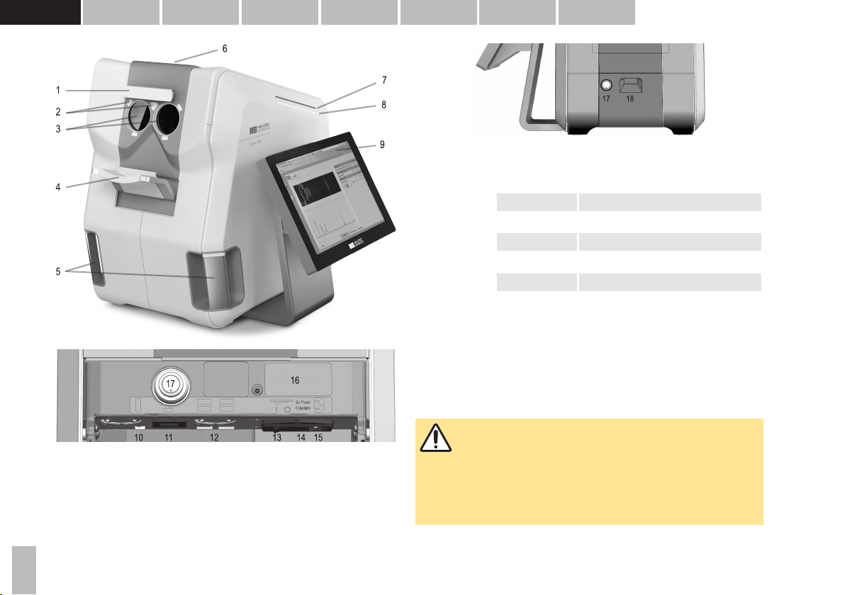
◦ 2.1 Basic construction..........................................................................................................................9
◦ 2.2 Operating principles.......................................................................................................................9
◦ 2.3 Eyestar 900 components ...............................................................................................................9
◦ 2.4 Device state indicator...................................................................................................................10
◦ 2.5 Touch screen ...............................................................................................................................10
¥ 3 Device assembly / installation ...........................................................................................10
◦ 3.1 Mains switch and power socket ...................................................................................................11
◦ 3.2 Power button................................................................................................................................11
◦ 3.3 LAN socket...................................................................................................................................11
◦ 3.4 USB sockets ................................................................................................................................11
◦ 3.5 Display port socket.......................................................................................................................11
◦ 3.6 Headband and chin rest...............................................................................................................11
◦ 3.7 Replacement of the headband.....................................................................................................11
◦ 3.8 Replacement of the chin rest tray ................................................................................................12
¥ 4 Operation.........................................................................................................................................12
◦ 4.1 Position of patient during measurement ......................................................................................12
◦ 4.2 Fixation ........................................................................................................................................12
◦ 4.3 Measured variables......................................................................................................................12
▪ 4.3.1 A-Scan..............................................................................................................................12
▪ 4.3.2 Keratometry ......................................................................................................................13
▪ 4.3.3 Topography, Elevation and Pachymetry...........................................................................13
▪ 4.3.4 White to white distance, pupillometry and eccentricity of the visual axis..........................13
¥ 5 Commissioning ...........................................................................................................................13
◦ 5.1 Switching on the device ...............................................................................................................13
◦ 5.2 Switching off the device ...............................................................................................................13
¥ 6 Technical data..............................................................................................................................14
◦ 6.1 General data ................................................................................................................................14
◦ 6.2 Power...........................................................................................................................................14
◦ 6.3 Illumination modalities .................................................................................................................14
▪ 6.3.1 OCT light source ..............................................................................................................14
▪ 6.3.2 Imaging system light source............................................................................................. 14
▪ 6.3.3 Primary fixation target ......................................................................................................14
▪ 6.3.4 Fellow eye fixation target.................................................................................................. 14
◦ 6.4 Measured variables .....................................................................................................................14
▪ 6.4.1 Central Corneal Thickness (CCT) ....................................................................................14
▪ 6.4.2 Anterior chamber depth (ACD)......................................................................................... 14
▪ 6.4.3 Lens thickness (LT).......................................................................................................... 14
▪ 6.4.4 Axial length (AL)............................................................................................................... 15
▪ 6.4.5 Keratometry (K)................................................................................................................ 15
▪ 6.4.6 White-to-white distance (WTW)........................................................................................ 15
▪ 6.4.7 Pupillometry (PD) .............................................................................................................15
◦ 6.5 Topography ................................................................................................................................. 15
▪ 6.5.1 Invivo repeatability standard topography (7.5 mm diameter) ...........................................15
▪ 6.5.2 Simulated Anterior Keratometry (SimK), standard topography (7.5 mm diameter).......... 16
▪ 6.5.3 Simulated Posterior Keratometry (SimPK), standard topography (7.5 mm diameter)...... 16
▪ 6.5.4 Invivo repeatability extended topography (12 mm diameter) ...........................................16
▪ 6.5.5 Simulated Anterior Keratometry (SimEK), extended topography (12 mm diameter)........ 17
▪ 6.5.6 Simulated Posterior Keratometry (SimEPK), extended topography (12 mm diameter) ...17
▪ 6.5.7 Normative considerations:................................................................................................ 17
▪ 6.5.8 Cristalline lens tilt .............................................................................................................17
¥ 7 Software / Help menu / Error messages...................................................................... 17
¥ 8 Maintenance.................................................................................................................................. 18
◦ 8.1 Cleaning ...................................................................................................................................... 18
¥ 9 Appendix......................................................................................................................................... 18
◦ 9.1 Accessories / consumables / spare parts / upgrade.................................................................... 18
◦ 9.2 Legal regulations .........................................................................................................................19
◦ 9.3 Classification ............................................................................................................................... 19
◦ 9.4 Disposal....................................................................................................................................... 19
◦ 9.5 Observed standards ....................................................................................................................19
◦ 9.6 Information and manufacturer's declaration concerning electromagnetic compatibility (EMC) ...19
▪ 9.6.1 General............................................................................................................................. 19
▪ 9.6.2 Emitted interference ......................................................................................................... 20
▪ 9.6.3 Electromagnetic immunity environment tested (part 1).................................................... 21
▪ 9.6.4 Electromagnetic immunity environment tested (part 2).................................................... 22
▪ 9.6.5 Recommended separation distances between portable and mobile RF communications
equipment and this product....................................................................................................... 24

4
DEUTSCHENGLISH FRANÇAIS ITALIANO ESPAÑOL NEDERLANDS
PORTUGUÊS SVENSKA
© HAAG‑STREIT AG, 3098 Koeniz, Switzerland – HS‑Doc. no. 1500.7220686.04020 – 2. Edition / 2021 – 05
1Safety
DANGER!
Failure to comply with these instructions may result in material damage
or pose a danger to patients or users.
WARNING!
These warnings must absolutely be complied with to guarantee safe
operation of the product and to avoid any danger to users and to
patients.
NOTE!
Important information: Please read carefully.
1.1 Areas of application of the device
The Eyestar 900 is an optical non contact Biometer providing measurements and
imaging of the eye from the cornea to the retina based on Swept Source OCT,
reflective Keratometry and Video image analysis technology. This device is intended
to be used in professional health care facilities such as hospitals, physician's,
optometrist's and optician's practices. For optimal use of the device, the ambient
lighting should be attenuated.
WARNING!
• This device must not be operated near of high frequency surgical
equipment and the radio frequency shielded room of a medical
electrical system for magnetic resonance imaging, where the
intensity of electromagnetic disturbances is high.
• Portable radio frequency communications equipment (including
peripherals such as antenna cables and external antennas) should
be used no closer than 30 cm (12 inches) to any part of the device,
including cables specified by Haag-Streit. Otherwise, degradation of
the performance of this device could result.
• If unexpected disturbances are observed the cause could be a cell
phone or radio frequency telephone in the immediate vicinity to the
Eyestar 900. Increase the distance to the device until the
interference disappears.
• Use of accessories, transducers and cables other than those
specified or provided by Haag-Streit could result in increased
electromagnetic emission or decreased electromagnetic immunity of
this device and result in improper operation.
1.2 Patient population
The patient must be capable of sitting up straight and keeping his head still. He must
be physically and mentally able to cooperate well and mentally capable of following
the examination. Patients must be at least 6 years old.
1.3 Ambient conditions
Temperature −40 °C ... +70 °C
Air pressure 500 hPa ... 1060 hPa
Transport
Relative humidity 10 % ... 95 %
Temperature −10 °C ... +55 °C
Air pressure 700 hPa ... 1060 hPa
Storage
Relative humidity 10 % ... 95 %
Temperature +10 °C ... +35 °C
Air pressure 800 hPa ... 1060 hPa
Use
Relative humidity 30 % ... 90 %
1.4 Shipment and unpacking
• Before unpacking the device, check whether the packaging shows traces of
improper handling or damage. If this is the case, notify the transport company
that delivered the goods to you. Unpack the equipment together with a
representative of the transport company. Make a report of any damaged parts.
This report must be signed by you and by the representative of the transport
company.

5
DEUTSCHENGLISHFRANÇAISITALIANOESPAÑOLNEDERLANDS PORTUGUÊS
SVENSKA
© HAAG‑STREIT AG, 3098 Koeniz, Switzerland – HS‑Doc. no. 1500.7220686.04020 – 2. Edition / 2021 – 05
• Leave the device in the packaging for a few hours before unpacking it
(condensation).
• Check the device for damage after it is unpacked.
• Return defective devices in the original packaging only. If the original packaging
got damaged during shipment, replacement packing may be ordered through
your local Haag-Streit representative.
• Store packaging material carefully, so that it can be used for possible returns or
when moving.
• Only use the original packaging material for moving the device.
• Check that the contents of the packaging correspond to the contents specified
on the leaflet included in the packaging.
• If packed in its original packing, then the device may comply with the transport
conditions according to ISO 15004-1.
• The device is designed for stationary use and should only be installed and
moved by skilled personnel, which is familiar with the installation manual.
1.5 Installation warnings
WARNING!
• Grounding reliability can only be achieved when unit is connected to
a hospital grade receptacle.
• The plug, cable and socket must function perfectly. The electrical
connection must feature safety earth.
• Before carrying out maintenance or cleaning work, the device must
always be disconnected from the mains by unplugging the power
supply or plug.
• Computers and further ancillary devices (printers, etc.) must comply
with the EN 60601-1 standard, or be connected with galvanic
isolation to external networks (isolating transformer, galvanic
Ethernet isolator, etc.).
• The device must be positioned in such a way that proper heat
dispersion / ventilation is guaranteed.
• The device should be set up in such a way that the plug is always
easily accessible and the device can easily be disconnected from
the mains.
• Use of this device adjacent to or stacked with other equipment
should be avoided because it could result in improper operation. If
such use is necessary, this device and the other equipment should
be observed to verify that they are operating normally.
1.6 Operation, environment
DANGER!
• It is not permitted to make modifications to the measuring device.
• It is expressly forbidden to open the device!
• Never use the device in potentially explosive environments where
flammable substances, volatile solvents (alcohol, benzene, etc.) and
combustible anesthetics are in use!
WARNING!
• The doctor or the operator is under an obligation to inform the
patient about safety instructions concerning them and to ensure that
these instructions are complied with.
• Only staff trained and experienced in the assessment of measuring
data and calculations and the manual entry, editing and deletion of
data may examine patients, operate the device and interpret results.
• All users must be appropriately trained and familiarized with the
contents of the instructions for use, especially with regard to the
safety instructions contained therein.
• Measurements can be carried out with dilated or undilated pupils.
Dilation of the pupil influences measurement of the pupil diameter
(pupillometry).
• Do not place any unapproved optical elements between the device
and the patient’s eye.
NOTE!
• This device may only be used for the purpose described in these
instructions for use.
• Installation only by trained specialists.

6
DEUTSCHENGLISH FRANÇAIS ITALIANO ESPAÑOL NEDERLANDS
PORTUGUÊS SVENSKA
© HAAG‑STREIT AG, 3098 Koeniz, Switzerland – HS‑Doc. no. 1500.7220686.04020 – 2. Edition / 2021 – 05
•If EyeSuite is used on an external PC for the review and further
analysis of the data acquired with the device, then the PC on which
the EyeSuite software is installed may not contain any other
software which could restrict the correct operation of EyeSuite.
• Please switch the device and or external computer off if it is not to
be used for a long time.
• The device may not be transported, stored, handled or operated
outside the specified ambient conditions (see chapter 'Ambient
conditions').
• The device is to be used in a room in the medical area with
attenuated light.
• If the device is moved/transported, a functional check must be
performed in accordance with the software instructions for use.
• If the device or accessories to it are exposed to the effects of an
external force (e.g., by being accidentally knocked or dropped), this
sensitive measuring device must be promptly checked according to
the software instructions for use and, if necessary, returned to the
factory for repair.
• The selected measuring mode must be checked before every
measurement.
• Keep these instructions for use in a place where they are accessible
at all times to those working with the device.
• Warranty claims can only be made if the instructions for use have
been complied with.
• The manufacturer of the device is not liable for loss or damage due
to unauthorised handling of the same. All warranty claims arising in
this case are null and void.
• Always remove the dust cover before switching the device on. If the
cover is not removed before switching the device on it may suffer
damage due to overheating. Likewise, make sure that the device is
switched off before attaching the dust cover.
• Repairs may only be conducted by suitably trained and authorised
specialist personnel. Incorrect repairs can pose considerable risks
for operating staff and patients.
• Housing parts of the device may only be removed by suitably trained
and authorised specialist personnel.
• Only original spare parts and original accessories may be used for
repairs.
• The software must be installed by trained personnel.
• Measurements should only be taken with the forehead rest band
and chin rest shell mounted correctly.
•Extensive amounts of ametropia of the patient may be corrected
using glasses or trial lenses during the measurement. Contact
lenses may not be used for this purpose as they would lead to
inaccurate measurement results.
• The patient should be advised to open his eyelids wide during the
measurement to allow best data acquisition.
• Unstable tear film, tear film breakup or dry eye syndrome may lead
to inaccurate and or instable measurements. It is recommended to
use artificial tears in such cases.
• It is recommended to set a user name and password for every user
of the device to best protect sensitive patient data.
• It is recommended and is in the responsibility of the user to protect
sensitive patient information using the access control (password
protection) on the device.
1.7 Plausibility of the measurements
WARNING!
• Users must check measurement readings for plausibility. This
includes the checking of the A and B-scan and the cursors, which
automatically adjust to the signal, the keratometry values, the white-
to-white distance and the pupillometry, whenever one of the
measurements displays an unusually high standard deviation. The
operator must also take into account the type (e.g., posterior
subcapsular cataract) and density of the cataract when evaluating
plausibility.

7
DEUTSCHENGLISHFRANÇAISITALIANOESPAÑOLNEDERLANDS PORTUGUÊS
SVENSKA
© HAAG‑STREIT AG, 3098 Koeniz, Switzerland – HS‑Doc. no. 1500.7220686.04020 – 2. Edition / 2021 – 05
• If the patient has previously undergone cataract surgery, available
records should be consulted for plausibility check of the
measurement.
• Prior to the measurement, the user must verify that the patient is not
wearing contact lenses. Wearing contact lenses will result in
erroneous measuring results.
• It may not be possible, under certain circumstances, to carry out
measurements on persons with fixation problems.
• In cases of thick cataracts and uncertain measurement of the axial
length, ultrasound biometry should be performed as a control
examination.
• Dense lenticular opacities may make it impossible to measure the
axial eye length and lens thickness.
• Pronounced opacities of the central cornea can likewise make it
impossible to measure corneal thickness, anterior chamber depth,
lens thickness or axial eye length.
• Blood in the vitreous may make it impossible to measure the axial
eye length.
• Keratometry may be erroneous in eyes that have undergone
keratorefractive surgery because such eyes may significantly
deviate from spherical surfaces.
• If the device repeatedly generates error messages, stop using it and
contact the customer service. These signs must be strictly adhered
to, to ensure safe operation of the device and to avoid endangering
users and patients.
• You are recommended to always examine both of the patient’s eyes.
The user should subject the measurement readings to extra scrutiny
if there is a notable difference between the right and left eye. The
following are classed as notable differences:
◦ More than 1 D with respect to central corneal refractive power
=> 0.18 mm difference with respect to the corneal curvature
radius
◦ More than 0.3 mm with respect to axial eye length
◦ More than 1 D with respect to emmetropic IOL refractive power
• The user must check the A and B-Scan when measuring anterior
chamber depth in pseudophakic mode. If only one IOL signal is
visible, it is not clear whether this signal relates to the front or back
of the IOL. Uncertainty in this case can lead to the displayed reading
for anterior chamber depth being inaccurate by the thickness of the
IOL (approx. ±1 mm).
• The measured corneal thickness is not intended as a basis for the
correction of intraocular pressure readings for diagnosing glaucoma.
• An excessively tilted or decentered IOL may make it impossible to
measure the anterior chamber depth, lens thickness and aqueous
depth.
• In young patients the signal from the crystalline lens might be low
and measurement of the anterior chamber depth, lens thickness and
aqueous depth might not be possible.
• Measurement readings obtained from patients with a non-intact
cornea (e.g., due to a corneal transplant, corneal opacity or corneal
scarring, etc.) may possibly be inaccurate (this applies to
keratometry in particular), and the user should check the data for
plausibility.
• Ambient light has an impact on pupil-diameter measurement
readings. The user is responsible for ensuring the correct level of
ambient light when carrying out pupillometry. The device does not
monitor ambient light, so do not use pupillometry as the decisive
factor when considering kerato-refractive surgery.
• Keratometry may not be accurate in eyes with keratoconus, and so
the user must verify its plausibility.
• The user must verify that the eye assignment (OD, OS) is correct for
the measured eye.
• The white-to-white distance reading is merely an indirect
measurement of the inner lateral dimensions of the anterior ocular
section. It therefore provides only approximate indications of the
actual inner lateral dimensions of the anterior ocular section and of
the size of the implant used.

8
DEUTSCHENGLISH FRANÇAIS ITALIANO ESPAÑOL NEDERLANDS
PORTUGUÊS SVENSKA
© HAAG‑STREIT AG, 3098 Koeniz, Switzerland – HS‑Doc. no. 1500.7220686.04020 – 2. Edition / 2021 – 05
• The measured results of patients with asteroid hyalosis may not be
accurate (in particular the axial length measurement) and must
therefore be verified by the user in terms of their plausibility.
1.8 IOL calculation
The measurements taken with the Eyestar 900 may serve as the central element for
the calculation of intraocular lenses (IOL). A further important parameter in
calculating the lens to be implanted is the IOL constant. When using the Eyestar
900, only IOL constants optimised for optical biometers should be used. Please
contact your IOL manufacturer for information on optimised IOL constants for optical
biometry. An alternative source of information for IOL constants optimised for optical
biometry is the website of the 'User Group for Laser Interference Biometry' (ULIB)
(http://ocusoft.de/ulib/c1.htm). Downloadable IOL Constants files for the Eyestar
900, featuring the ULIB IOL-Constants for the formulas implemented in EyeSuite
IOL are available in the Key-User section of the Haag-Streit homepage.
To further improve the clinical result, Haag-Streit recommends that every surgeon
creates personally optimised IOL constants based on pre-operative measurement
data generated with the Eyestar 900 and reliable postoperative data (e.g., 3 months
after the operation).
1.9 Optical radiation
WARNING!
The light of this device may de dangerous. The risk of eye damage
increases with the number of examinations in succession per eye. An
examination time with this device of over 225 individual examinations
exceeds the risk guideline value.
NOTE!
• This device complies with the light exposure limits for class 2
ophthalmic devices according to EN ISO 15004-2:2007.
•This device is a class 1 laser device in accordance with IEC
60825-1.
• The device complies with the exempt (risk free) group in accordance
with IEC 62471.
1.10 Disinfection
NOTE!
• The device does not need to be disinfected.
• The device complies with the exempt (risk free) group in accordance
with IEC 62471:2006
For more information on cleaning, please refer to the ‘Maintenance’ chapter.
1.11 Warranty and product liability
• Haag-Streit products must be used only for the purposes and in the manner
described in the documents distributed with the product.
• The product must be treated as described in the ‘Safety’ chapter. Improper
handling can damage the product. This would void all guarantee claims.
• Continued use of a product damaged by incorrect handling may lead to personal
injury. In such a case, the manufacturer will not accept any liability.
• Haag-Streit does not grant any warranties, either expressed or implied, including
implied warranties of merchantability or fitness for a particular use.
• Haag-Streit expressly disclaims liability for incidental or consequential damage
resulting from the use of the product.
• This product is covered by a limited warranty granted by your seller.
For USA only:
• This product is covered by a limited warranty, which may be reviewed at
www.haag-streit-usa.com.
1.12 Description of symbols
Follow instruction for use Read the instructions for use
attentively
General warning: Read the
accompanying documentation
European certificate of
conformity
Date of manufacture Manufacturer

9
DEUTSCHENGLISHFRANÇAISITALIANOESPAÑOLNEDERLANDS PORTUGUÊS
SVENSKA
© HAAG‑STREIT AG, 3098 Koeniz, Switzerland – HS‑Doc. no. 1500.7220686.04020 – 2. Edition / 2021 – 05
HS reference number Serial number
Trademark of the manufacturer
Haag-Streit AG
Notes on disposal, see the
'Disposal' chapter
Listed European Authorized
Representative Medical Device
Testsymbol of TÜV Rheinland
with approval for INMETRO
Brasil
MET Listed Mark with approval
for USA and Canada
Disconnect the plug before
opening the device Warning for laser beam
Type B applied part Housing protection
Alternating current Direct current
2Introduction
2.1 Basic construction
The Eyestar 900 is an all in one optical biometry device, containing a measuring
head and internal computer for signal processing and display of results. The unit is
operated via a touch screen interface and some buttons at the device housing.
EyeSuite is the software that runs the unit and is pre-installed on the built in
computer. Integral, automatic error recognition for the measurements guarantees
reliable examination results.
2.2 Operating principles
The Eyestar 900 is a non-contact device consisting of a swept source OCT subunit
(OCT: optical coherence tomography, a measurement method to acquire
tomographic images by optical interferometry) and an imaging system sub-unit.
The OCT sub-unit performs a three-dimensional measurement of all refractive
ocular structures in the anterior eye segment (curvatures and locations of anterior
corneal surface, posterior corneal surface, anterior crystalline lens surface, posterior
crystalline lens surface), as well as a one-dimensional measurement of axial eye
length. It also generates cross-sectional images of the anterior eye section and the
central retina. The measurement is implemented by scanning the eye with a
lowpower near-infrared laser beam and measuring the light which is back-reflected
to the device. The imaging system sub-unit is used to obtain photographic images of
the eye. Based on these images, the white-to-white distance and the pupil diameter
are measured. Additionally, these images can serve to document the locations of
special landmarks on the eye, such as blood vessels. Illumination for imaging is
provided by infrared and white-light LEDs (light emitting diodes).
2.3 Eyestar 900 components
1. Forehead rest band (applied part,
removable part)
2. Front illumination (5 pieces)
3. Ocular (left and right)
4. Height adjustable chin rest
(applied part, removable part)
5. Hand grips for patient (applied
part)
6. Multifunction buttons
7. Ventilation groove
8. Device state indicator
9. Touch screen
10. Display port socket
11. LAN port socket (Gigabit)
12. USB port sockets (2 × USB 2.0 / 2
× USB 3.0)
13. Mains switch
14. Fuses (2 × T2AH, 250V)
15. Mains socket
16. Type Plate
17. Power button
18. Connector panel cover

10
DEUTSCHENGLISH FRANÇAIS ITALIANO ESPAÑOL NEDERLANDS
PORTUGUÊS SVENSKA
© HAAG‑STREIT AG, 3098 Koeniz, Switzerland – HS‑Doc. no. 1500.7220686.04020 – 2. Edition / 2021 – 05
2.4 Device state indicator
The device state indicator allows device monitoring without PC software:
State indicator Dark Device is turned off
Pulsing orange Standby
Green On, no measurement in process
Blue Light source is on for measurement
Red Device error
2.5 Touch screen
The touch screen panel is mounted in the right side from the patient’s point of view
as a default location. I may also be mounted on the rear of the device or on the left.
Adjustments of the screen location must be carried out by trained service personnel
only.
3 Device assembly / installation
WARNING!
• The device must be installed by trained personnel in accordance
with the installation instructions provided in the separate service
installation manual.
•Whenever the Eyestar 900 is connected to any external electronic
device, then the user has to ensure that the configuration is in
accordance with safety regulations according to EN 60601-1. This

11
DEUTSCHENGLISHFRANÇAISITALIANOESPAÑOLNEDERLANDS PORTUGUÊS
SVENSKA
© HAAG‑STREIT AG, 3098 Koeniz, Switzerland – HS‑Doc. no. 1500.7220686.04020 – 2. Edition / 2021 – 05
may be achieved by e.g. use of a medical grade insulation
transformer or a medical grade power supply to power the external
screen.
• For further information, please contact your Haag-Streit
representative.
3.1 Mains switch and power socket
The mains connector of the Eyestar 900 is a C 13 Socket. It is located under the
device and allows invisible cable management if the device is used on a table
(optional) that features a respective aperture for the mains and other cables (e.g.
LAN). Use the mains switch to turn the device off if it is not used for a longer time
period or if the device is covered with the optional dust cover, to prevent accidental
power up and possible overheating. The integral power supply works with the
voltages specified under chapter 6.2 'Power'. It is not necessary to select the voltage
on the device.
3.2 Power button
The power button is used to switch the device from standby to on and back to stand
by if the mains cable is connected and the mains switch is turned on. The status
indicator informs the user on the current state of the device.
3.3 LAN socket
The LAN socket enables the Eyestar 900 to be connected to a local area network.
This is used to run the Eyestar 900 in a DICOM or EMR environment or to access
an external EyeSuite database enabling the assessment of measurements on PC
viewing stations with an EyeSuite installation. For more details on the network and
EMR integration capabilities of the device, check the EyeSuite software instructions
for use accessible in the software.
3.4 USB sockets
The Eyestar 900 features four (4) USB sockets, two features USB 2.0 and two
features USB 3.0 standard. They may be used to connect an external hard drive to
the device for backup of data or to import e.g. IOL definition files from a memory
stick. They may also be used to connect an optional keyboard and / or mouse and to
connect to a printer. For more information how to install a printer on the device,
check the EyeSuite software instructions for use accessible in the software.
3.5 Display port socket
Eyestar 900 also features a display port socket. This enables the user to display the
Eyestar 900’s user interface on a 2nd external screen.
3.6 Headband and chin rest
For cleaning and periodical exchange, the headband as well as the chin rest may be
removed from the device. It is recommended to replace either part if it shows
physical damage to the surface and edge or if they have been in use for more than
two years.
3.7 Replacement of the headband
The headband is held in place with a click / slide mechanism. To remove it, push in
the middle of the headband and pull on the left edge of the headband to loosen the
slide mechanism. After the left side is loose, pull on the left edge to unclick it from its
mount on the device.
Clean the headband as described in chapter 8.1 'Cleaning'.
To mount the headband again, first click it in on the right side then slide it back in on
the left.

12
DEUTSCHENGLISH FRANÇAIS ITALIANO ESPAÑOL NEDERLANDS
PORTUGUÊS SVENSKA
© HAAG‑STREIT AG, 3098 Koeniz, Switzerland – HS‑Doc. no. 1500.7220686.04020 – 2. Edition / 2021 – 05
3.8 Replacement of the chin rest tray
Grasp the chin rest tray (black plastic part) with your thumb and index finger. Now
pull it towards you. The tray will slide from the metal chin rest mechanism on the
device. Clean the chin rest tray as described in chapter 8.1 'Cleaning'.
To mount the chin rest tray again slide it back on the metal chin rest mechanism
until you may not pull it further in.
4Operation
4.1 Position of patient during measurement
NOTE!
Prior to the measurement procedure, clean the patient interface
forehead rest band, chin rest shell and both handles including their
supporting parts as described in chapter 8.1 'Cleaning'.
A steady head position is promoted by resting the patient’s head in good contact
with the chin rest and forehead rest band, and by the patient holding on to the hand
grips. This can positively influence adjustment time and measuring accuracy.
The patient should sit upright, in a relaxed position. Adjust the height of the
instrument table and chair of the patient to allow a relaxed lightly downwards
directed gaze position. The height adjustment of the chin rest is performed via the
touch screen user interface or the two arrow-multifunction buttons on top of the
device. Additional height indication marks at the device cover representing the eye
height level and may help position the chin rest in a good initial position. Details on
the measurement process are described in the software instructions for use of the
device.
WARNING!
• Always check the chosen measure mode and patient settings.
• Do not place any unapproved optical elements between the device
and the patient’s eye.
• The motorized chin rest may pose a crushing hazard.
NOTE!
In order to get the best possible results, the patient should be requested
to keep the eye as wide open as possible during the measurement and
to focus on the fixation target. The measurement starts when the fixation
target changes its color from green to blue. The measurement is
finished when the fixation target turns green again. Blinking is permitted
throughout the measurement process, but should be kept to a minimum.
Patients with tremor might be assisted by the user or a third person in
holding their head still.
4.2 Fixation
To obtain reliable results, the patient must stare at the multi-color fixation target in
the measuring lens during measurement.
4.3 Measured variables
4.3.1 A-Scan
Depending on the patient’s gaze at the fixation target, the optical path length of the
visual axis is measured:

13
DEUTSCHENGLISHFRANÇAISITALIANOESPAÑOLNEDERLANDS PORTUGUÊS
SVENSKA
© HAAG‑STREIT AG, 3098 Koeniz, Switzerland – HS‑Doc. no. 1500.7220686.04020 – 2. Edition / 2021 – 05
CCT Central corneal thickness
AD Aqueous depth (Back of the cornea to front of
the lens)
ACD Anterior chamber depth
LT Lens thickness
AL Axial eye length (Front of the cornea to inner
limiting membrane)
NOTE!
Since the device measures up to the retinal pigmented epithelium, the
reading displayed is adjusted to the internal limiting membrane, either
automatically, as a function of axial length, or manually, according to the
mode selected. (Manual correction is not available in the USA).
4.3.2 Keratometry
The values displayed (flat radius, steep radius)
correspond to the radii of an ellipsoid that fits into the
cornea. The axis of its rotation is measured counter-
clockwise from the horizontal to the flat radius.
• a: Flat radius
• b: Steep radius
• c: Axis of rotation
4.3.3 Topography, Elevation and Pachymetry
The device provides the user with surface information of the cornea in the following
formats:
• Anterior and posterior axial curvature map
• Anterior and posterior tangential curvature map
• Total corneal power map
• Anterior and posterior elevation map
• Anterior and posterior irregularity map
• Pachymetry map
4.3.4 White to white distance, pupillometry and eccentricity of
the visual axis
The white-to-white distance (WTW) is determined using the image of the iris and the
eye radii obtained from keratometry. The value displayed corresponds to the
diameter of an ideal circle.
Pupil diameter (Ø) corresponds to the diameter of an ideal circle, with the smallest
error perpendicular to the established pupil border. At the same time, the shift of
visual axis towards the centre of the pupil is provided. The calculated dimensions
are located on the theoretically derived level of the iris. The image enlargement
achieved by the refraction of the eye is disregarded.
5 Commissioning
The device is powered though an integrated medical grade power supply, it works
with the voltages specified under chapter 6.2 'Power'. It is not necessary to select
the voltage on the device. Ensure that the power cable used always features the
safety earth pin and that the respective pin is functional on the socked used.
5.1 Switching on the device
• Connect the power plug to the mains.
• Switch on the main switch.
• Start the device by pressing the stand-by / on button.
5.2 Switching off the device
•Exit the software on the device or press the stand-by / on button for more than 3
seconds.
• Only switch of the main switch after the internal computer was shut down and
the screen is blank.
• Disconnect the power from the mains if you do not intend to use the device for
an extended period of time.

14
DEUTSCHENGLISH FRANÇAIS ITALIANO ESPAÑOL NEDERLANDS
PORTUGUÊS SVENSKA
© HAAG‑STREIT AG, 3098 Koeniz, Switzerland – HS‑Doc. no. 1500.7220686.04020 – 2. Edition / 2021 – 05
6 Technical data
6.1 General data
Type designation: Eyestar 900
Dimensions: 480 × 560 × 460 mm
Weight: 31.0 kg
6.2 Power
Input: 100 – 240 VAC, 50 – 60 Hz, 200 VA
6.3 Illumination modalities
6.3.1 OCT light source
Light source: Wavelength tunable laser
Wavelength range: 1030 nm … 1080 nm
Power on patient’s eye ≤ 2.0 mW
6.3.2 Imaging system light source
Light source: Infrared and warm white LEDs
Wavelength: 850 nm (IR)
warm white
6.3.3 Primary fixation target
Light source: LEDs
Wavelength: 525 nm (green)
624 nm (red)
6.3.4 Fellow eye fixation target
Light source: LEDs
Wavelength: 625 nm (red)
6.4 Measured variables
In-vivo repeatabilities reported in this chapter are based on N=46 eyes (one eye per
subject). 32 phakic (healthy and cataract) and 14 pseudophakic eyes were included.
In-vivo repeatability is calculated as the standard deviation of pairwise differences of
three repeated measurements per eye for all eyes. Aphakic and oil-filled eyes can
be measured with the device. The reported in vivo repeatability does not include
these eye types.
6.4.1 Central Corneal Thickness (CCT)
Measurement range: 300 - 800 μm
Display resolution: 1 μm
In vivo repeatability (1. SD): ± 1.5 μm
6.4.2 Anterior chamber depth (ACD)
Measurement range: 1.8 - 6.3 mm
Display resolution: 0.01 mm
In vivo repeatability (1. SD): ± 0.014 mm
6.4.3 Lens thickness (LT)
Measurement range: 0.5 - 6.5 mm
Display resolution: 0.01 mm
In vivo repeatability (1. SD): ± 0.015 mm

15
DEUTSCHENGLISHFRANÇAISITALIANOESPAÑOLNEDERLANDS PORTUGUÊS
SVENSKA
© HAAG‑STREIT AG, 3098 Koeniz, Switzerland – HS‑Doc. no. 1500.7220686.04020 – 2. Edition / 2021 – 05
6.4.4 Axial length (AL)
Measurement range: 14 - 38 mm
Display resolution: 0.01 mm
In vivo repeatability (1. SD): ± 0.005 mm
6.4.5 Keratometry (K)
Measurement range K: 32.1 - 67.5 dpt
Display resolution K: 0.01 dpt
In vivo repeatability Kmean (1. SD): ± 0.067 dpt
In vivo repeatability AST (1. SD): ± 0.127 dpt
Measurement range Axis: 0 - 180°
Display resolution Axis: 1°
In vivo repeatability Axis, 0.5 dpt < AST ≤ 1.5 dpt (1. SD): ± 4.5°
In vivo repeatability Axis, AST > 1.5 dpt (1. SD): ± 1.6°
6.4.6 White-to-white distance (WTW)
Measurement range: 7 - 16 mm
Display resolution: 0.01 mm
In vivo repeatability (1. SD): ± 0.079 mm
6.4.7 Pupillometry (PD)
Measurement range: 2 - 13 mm
Display resolution: 0.01 mm
6.5 Topography
In-vivo repeatabilies reported in this chapter are based on a clinical investigation
with N = 29 subjects, including 42 eyes with healthy cornea and 16 eyes with
irregular corneal shape, comprising the following pathologies/treatments:
Keratoconus, DSAEK, corneal crosslinking, Pseudoexfoliation Syndrome, corneal
transplant, susp. Salzmann degeneration, corneal lesion, corneal indentation. Only
one eye per subject per class (healthy cornea, irregular corneal shape) is included in
the analysis.
Covered area (diameter): Standard 7.5 mm / Extended 12 mm
6.5.1 Invivo repeatability standard topography (7.5 mm
diameter)
This repeatability table is based on N=32 eyes (including 9 eyes with irregular
corneal shape), with three measurements per eye.
Area
Center zone Middle zone Outer zone
Measurand Unit
Mean1) 2 Std.
Dev.2)
Mean 2 Std.
Dev.
Mean 2 Std.
Dev.
Anterior corneal curvature dpt 0.25 0.44 0.12 0.36 0.092 0.44
Posterior corneal
curvature
dpt 0.027 0.064 0.018 0.050 0.015 0.062
Anterior elevation μm – 2.9 – 3.9 – 5.1
Posterior elevation μm – 2.9 – 4.8 – 5.9
Pachymetry μm – 2.2 – 3.7 – 4.7
Areas indicate the center zone (diameter ≤ 3 mm), middle zone (3 mm < diameter ≤
6 mm) and outer zone (diameter > 6 mm) regions of the cornea.
1) Mean: Standard deviation of the mean difference between paired data sets.
2) 2 Std. Dev.: Twice the mean of the standard deviation of differences between paired data sets.

16
DEUTSCHENGLISH FRANÇAIS ITALIANO ESPAÑOL NEDERLANDS
PORTUGUÊS SVENSKA
© HAAG‑STREIT AG, 3098 Koeniz, Switzerland – HS‑Doc. no. 1500.7220686.04020 – 2. Edition / 2021 – 05
6.5.2 Simulated Anterior Keratometry (SimK), standard
topography (7.5 mm diameter)
Reported in-vivo repeatabilities are based on N=32 eyes, including 9 eyes with
irregular corneal shape. In-vivo repeatability is calculated as the standard deviation
of pairwise differences of three repeated measurements per eye for all eyes.
Measurement range SimK: 32.1 - 67.5 dpt
Display resolution SimK: 0.01 dpt
In vivo repeatability SimKmean (1. SD): ± 0.22 dpt
In vivo repeatability SimAST (1. SD): ± 0.18 dpt
Measurement range SimAxis: 0 - 180°
Display resolution SimAxis: 1°
In vivo repeatability SimAxis, 0.5 dpt < AST ≤ 1.5 dpt (1. SD): ± 3.7°
In vivo repeatability SimAxis, AST > 1.5 dpt (1. SD): ± 2.1°
Display resolution Corneal Shape Factor: 0.01
In vivo repeatability Corneal Shape Factor: 0.07
6.5.3 Simulated Posterior Keratometry (SimPK), standard
topography (7.5 mm diameter)
Reported in-vivo repeatabilities are based on N=31 eyes, including 8 eyes with
irregular corneal shape. In-vivo repeatability is calculated as the standard deviation
of pairwise differences of three repeated measurements per eye for all eyes.
Measurement range SimPK: 3.9 - 9.5 dpt
Display resolution SimPK: 0.01 dpt
In vivo repeatability SimPKmean (1. SD): ± 0.032 dpt
In vivo repeatability SimPAST (1. SD): ± 0.029 dpt
Measurement range SimPAxis: 0 - 180°
Display resolution SimPAxis: 1°
In vivo repeatability SimPAxis, SimPAST > 0.5 dpt (1. SD): no occurrences
Display resolution Posterior Corneal Shape Factor: 0.01
In vivo repeatability Posterior Corneal Shape Factor: 0.09
6.5.4 Invivo repeatability extended topography (12 mm
diameter)
This repeatability table is based on N=31 eyes (including 8 eyes with irregular
corneal shape), with three measurements per eye.
Area
Center zone Middle zone Outer zone
Measurand Unit
Mean1) 2 Std.
Dev.2)
Mean 2 Std.
Dev.
Mean 2 Std.
Dev.
Anterior corneal curvature dpt 0.17 0.32 0.084 0.30 0.063 0.36
Posterior corneal
curvature
dpt 0.025 0.052 0.013 0.056 0.011 0.072
Anterior elevation μm – 2.8 – 4.6 – 6.5
Posterior elevation μm – 2.7 – 5.5 – 8.9
Pachymetry μm – 2.5 – 4.2 – 7.5
Areas indicate the center zone (diameter ≤ 3 mm), middle zone (3 mm < diameter ≤
6 mm) and outer zone (diameter > 6 mm) regions of the cornea.
1) Mean: Standard deviation of the mean difference between paired data sets.
2) 2 Std. Dev.: Twice the mean of the standard deviation of differences between paired data sets.

17
DEUTSCHENGLISHFRANÇAISITALIANOESPAÑOLNEDERLANDS PORTUGUÊS
SVENSKA
© HAAG‑STREIT AG, 3098 Koeniz, Switzerland – HS‑Doc. no. 1500.7220686.04020 – 2. Edition / 2021 – 05
6.5.5 Simulated Anterior Keratometry (SimEK), extended
topography (12 mm diameter)
Reported in-vivo repeatabilities are based on N=30 eyes, including 7 eyes with
irregular corneal shape. In-vivo repeatability is calculated as the standard deviation
of pairwise differences of three repeated measurements per eye for all eyes.
Measurement range SimEK: 32.1 - 67.5 dpt
Display resolution SimEK: 0.01 dpt
In vivo repeatability SimEKmean (1. SD): ± 0.14 dpt
In vivo repeatability SimEAST (1. SD): ± 0.095 dpt
Measurement range SimEAxis: 0 - 180°
Display resolution SimEAxis: 1°
In vivo repeatability SimEAxis, 0.5 dpt < AST ≤ 1.5 dpt (1.
SD):
± 2.6°
In vivo repeatability SimEAxis, AST > 1.5 dpt (1. SD): ± 2.4°
Display resolution Corneal Shape Factor: 0.01
In vivo repeatability Corneal Shape Factor: 0.05
6.5.6 Simulated Posterior Keratometry (SimEPK), extended
topography (12 mm diameter)
Reported in-vivo repeatabilities are based on N=29 eyes, including 6 eyes with
irregular corneal shape. In-vivo repeatability is calculated as the standard deviation
of pairwise differences of three repeated measurements per eye for all eyes.
Measurement range SimEPK: 3.9 - 9.5 dpt
Display resolution SimEPK: 0.01 dpt
In vivo repeatability SimEPKmean (1. SD): ± 0.019 dpt
In vivo repeatability SimEPAST (1. SD): ± 0.023 dpt
Measurement range SimEPAxis: 0 - 180°
Display resolution SimEPAxis: 1°
In vivo repeatability SimEPAxis, SimEPAST > 0.5 dpt (1. SD): no occurrences
Display resolution Posterior Corneal Shape Factor: 0.01
In vivo repeatability Posterior Corneal Shape Factor: 0.06
6.5.7 Normative considerations:
Eyestar 900 complies with the standard EN ISO 19980:2012 for corneal topography
systems, type A.
6.5.8 Cristalline lens tilt
Reported in-vivo repeatabilities are based on N=28 phakic eyes (one eye per
subject). In-vivo repeatability is calculated as the standard deviation of pairwise
differences of three repeated measurements per eye for all eyes.
Crystalline lens tilt
measurand
unit measured in-vivo
repeatability base on
standard topograhy (7.5
mm)
measured in-vivo
repeatability base on
extended topograhy (12
mm)
Lens tilt, axial angle ° 0.1 0.1
Lens tilt, rotational
angle
° 2.3 1.8
Lens decentration X,
Lens DX
μm 10.3 8.4
Lens decentration Y,
Lens DY
μm 8.7 7.1
7 Software / Help menu / Error messages
The software’s help section contains instructions and help for performing an
examination and descriptions of the error messages. The help can be opened via
the F1 key or in the [?] – [Help] menu.

18
DEUTSCHENGLISH FRANÇAIS ITALIANO ESPAÑOL NEDERLANDS
PORTUGUÊS SVENSKA
© HAAG‑STREIT AG, 3098 Koeniz, Switzerland – HS‑Doc. no. 1500.7220686.04020 – 2. Edition / 2021 – 05
WARNING!
The software must be installed by trained personnel in accordance with
the separate installation instructions. For further information, please
contact your Haag-Streit representative.
NOTE!
• The instructions for use is integrated into the software.
•Error messages are described in the software instructions for use.
8 Maintenance
The Eyestar 900 is practically maintenance-free and requires only minimum care to
work for as long as possible to your complete satisfaction. However, we recommend
instructing a service engineer to inspect the biometer periodically. Haag-Streit or
your local representative will be happy to provide further information.
8.1 Cleaning
The cleaning intervals for cleaning the complete device shall be performed within
reasonable time (e.g. once a week). Cleaning of applied parts shall be performed
prior to the measurement procedure with a new patient.
Please use only following tools for cleaning operations:
• Cleaning liquid: Isopropanol 2 (cleaning liquid with maximum 70 % alcohol)
• Cover towel: Commercially available towel
• Display towel: Commercially available towel for cleaning screens
• HS Lenspen (see appendix)
In particular, attention has to be paid to the following points:
• Only use cleaning liquid evenly spread on the cover towel on following device
parts:
• Patient interface chin rest shell including its supporting parts
• Patient interface forehead rest band including its supporting parts
• Patient interface handles including their supporting parts
• Device cover (casing)
• User interface display panel
• User interface display panel surroundings and stand
The device patient interface cover glasses shall only be cleaned with the HS
Lenspen.
WARNING!
Only perform maintenance on a powered off device.
We suggest following cleaning procedure:
• Put cleaning liquid evenly spread on the cover towel
• Clean the patient interface forehead rest band, chin rest shell and both handles
including their supporting parts with the cover towel
• Put cleaning liquid evenly spread on the cover towel
• Clean the complete device cover with the cover towel
• Put cleaning liquid evenly spread on the cover towel
• Clean the display panel surroundings and stand with the cover towel
• Clean the display panel (control panel) with the display towel
• Clean the patient interface cover glasses with the HS Lenspen with the felt and
the brush
• Protect the device from dust with the dedicated accessory dust cover when the
device is not in use.
WARNING!
The device must not be switched on when covered! (Heat build-up, fire
hazard).
9Appendix
9.1 Accessories / consumables / spare parts / upgrade
Components REF
Chin rest shell 1022709
Forehead rest band 1022903
Cable Power Inlet Adapter 1023026
Packaging 1023037

19
DEUTSCHENGLISHFRANÇAISITALIANOESPAÑOLNEDERLANDS PORTUGUÊS
SVENSKA
© HAAG‑STREIT AG, 3098 Koeniz, Switzerland – HS‑Doc. no. 1500.7220686.04020 – 2. Edition / 2021 – 05
Dust Protection Cover 1802304
HS Lenspen 1820415
9.2 Legal regulations
•Haag-Streit maintains a quality management system in accordance with EN ISO
13485. The device has been developed and designed taking into consideration
all the standards listed in chapter 'Observed standards'.
• This is a Class IIa device in accordance with Appendix IX of Directive 93/42/
EEC. By affixing the CE mark we confirm that our device complies with the
applicable standards and directives.
• You can request a copy of the declaration of conformity for the device from
Haag-Streit at any time.
9.3 Classification
EN 60601-1:2006+A1:2013/AN Continuous operation
EN 60825-1:2014 Laser class I
EN 60529:1991+A1:2000 Enclosure protection IP20
EN 62471:2008 Exempt group
EN ISO 15004-2:2007 Group 2
ISO 19980:2012 Corneal topographer, type A
93/42/EEC (medical devices) Class IIa
9.4 Disposal
Electrical and electronic devices must be disposed of separately
from household waste! This device was made available for sale
after the 13th August 2005. For correct disposal, please contact
your Haag-Streit representative. This will guarantee that no
hazardous substances enter the environment and that valuable raw
materials are recycled.
9.5 Observed standards
EN 60601-1 EN 60529
EN 60601-1-2 EN ISO 15004-1
EN 62471 EN ISO 15004-2
EN 60825-1 EN ISO 19980
9.6 Information and manufacturer's declaration concerning
electromagnetic compatibility (EMC)
9.6.1 General
This device fulfills the requirements on electromagnetic compatibility according to
IEC 60601-1-2:2014 (4th Edition). The device is built so that the generation and
emission of electromagnetic interference is limited to the extent that other devices
are not disturbed in their use in accordance with the regulations and so that the
device itself is suitably immune to electromagnetic interference.
WARNING!
•Electrical medical devices and systems are subject to special EMC
measures and must be installed in accordance with the EMC
instructions contained in this accompanying document.
• Portable and mobile HF communication systems may interfere with
electrical medical devices.
• Use of accessories, transducers and cables other than those
specified or provided by Haag-Streit could result in increased
electromagnetic emissions or decreased electromagnetic immunity
of this device and result in improper operation.

20
DEUTSCHENGLISH FRANÇAIS ITALIANO ESPAÑOL NEDERLANDS
PORTUGUÊS SVENSKA
© HAAG‑STREIT AG, 3098 Koeniz, Switzerland – HS‑Doc. no. 1500.7220686.04020 – 2. Edition / 2021 – 05
9.6.2 Emitted interference
This product is intended for use in the electromagnetic environment specified below. The customer or the user of this product should assure that it is used in such an
environment.
Emission test Compliance Electromagnetic environment - guidance
RF emissions
CISPR 11
Group 1 This product uses RF energy only for its internal function. Therefore, its RF emissions are very low
and are not likely to cause any interference in nearby electronic equipment.
RF emissions
CISPR 11
Class B
Harmonics emissions
IEC 61000-3-2
Class A
Voltage fluctuations/flicker emissions
IEC 61000-3-3
Pst = 1.0
Plt = 0.65
This product is suitable for use in all establishments, including domestic establishments and those
directly connected to the public low-voltage power supply network that supplies buildings used for
domestic purposes.
Pst: Power short term flicker
Plt: Power long term flicker
Other manuals for Eyestar 900
2
Table of contents
Other Haag-Streit Measuring Instrument manuals
Popular Measuring Instrument manuals by other brands

ATAGO
ATAGO PAL-Easy ACID181 instruction manual

Assured Automation
Assured Automation WM-NLD Series Installation, operation & maintenance manual

Fluidwell
Fluidwell D Series manual

Desco
Desco 19651 Installation, operation and maintenance

Stabila
Stabila LAR 160 operating instructions

wtw
wtw Cond 3110 quick start guide