Haas+Sohn HRT 160 Operating manual

Haas Technical Publications
Manual_Archive_Cover_Page Rev A
June 6, 2013
• This content is for illustrative purposes.
• Historic machine Service Manuals are posted here to provide information for Haas machine owners.
• Publications are intended for use only with machines built at the time of original publication.
• As machine designs change the content of these publications can become obsolete.
•You should not do mechanical or electrical machine repairs or service procedures unless you are qualied
and knowledgeable about the processes.
•Only authorized personnel with the proper training and certication should do many repair procedures.
HAAS SERVICE AND OPERATOR MANUAL ARCHIVE
WARNING: Some mechanical and electrical service procedures can be
extremely dangerous or life-threatening.
Know your skill level and abilities.
All information herein is provided as a courtesy for Haas machine owners
for reference and illustrative purposes only. Haas Automation cannot be held
responsible for repairs you perform. Only those services and repairs that are
provided by authorized Haas Factory Outlet distributors are guaranteed.
Only an authorized Haas Factory Outlet distributor should service or repair a
Haas machine that is protected by the original factory warranty. Servicing by
any other party automatically voids the factory warranty.
HRT Operator Manual 96-5047 RevL English June 2005

1
96-5047 rev L June 2005
Back
1. INTRODUCTION
1.1 D
ESCRIPTION
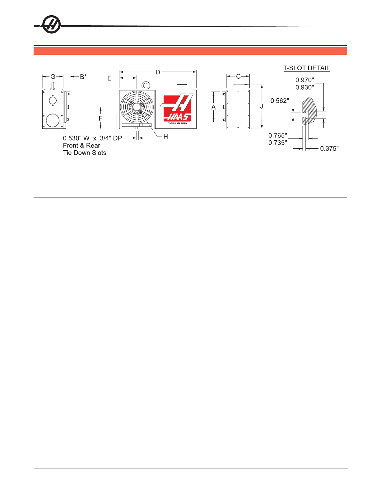
The HAAS rotary table is a fully automatic, programmable, rotary positioning device. The unit is made up of two
parts: the mechanical table that holds the workpiece and the electronic unit that controls the rotation of the
table. Positioning of the workpiece is accomplished by programming the angular movements into the memory
of the control and then pushing the CYCLE STARTbutton on the front panel.
The unit was specifically designed for rapid positioning of parts in secondary operations such as milling,
drilling, and tapping. The device is especially suited to automatic machines such as NC mills and automatic
productionmachines.Thecontrolcanberemotelyactivatedbyyourequipmentanddoesnotrequirehuman
assistance,resultinginfully automatic operation. Furthermore, one unit can be used on several different
machines, thereby eliminating the need for multiple units.
TABLE
The rotary table can be used in almost all of the applications where a manual rotary table can be used. Posi-
tioningofthetableisaccomplishedthroughadeep-toothengaging,self-lockingwormandwormgearset.The
worm is connected to aAC (DC) servo motor through a timing belt and pulley set. Odd number bolt circles and
unevenholespacingareeasilyhandledwithsimpleprogramming.Thetableisequippedwithapneumatic
brake (HRT450 uses air over oil).Aregular shop air line of approximately 100 PSI is all that is needed to
activatethebrake.
TheHRT210SHS(Super-HighSpeed)Table is unique from the other rotarytables.Ithasnowormgear set, belt,
or pulleys but uses a “Harmonic Drive” gear. It is directly driven by anAC servo motor and is 6 times faster than
ourstandardHRT210.
TheHRT320FBusesafacegear(Hirthcoupling)forextremeindexingaccuracyandrigidity.Itpositionsthe
platter in multiples of exactly 1° . The platter lifts .070” during indexing and the table positioning is done at full
rapid speed. The HRT320FB cannot be used as a full forth axis.
CONTROL
Therotarytableservocontrolincorporatesthelatestinhigh-speedmicroprocessors and drive technology.The
controlwasdesignedusingextensivesoftwaretoreplacediscretecomponents,therebyreducingpossible
failure areas. This same software also checks out the computer system upon power-up, and alerts you to
component failures. Only one printed circuit board is used to control all major functions.
The optional RS-232 interface can be used to upload, download, enter data, read position, start, and stop motor
operation.

296-5047 rev L June 2005
1.2 LIMITATIONS
The control and table are described as a “semi-fourth axis”. This means that the table cannot do simultaneous
interpolation with other axes. Linear moves or spirals can be generated by having an axis of your mill move at
the same time the rotary table moves (see the "Programming" section for details).
1.3 MACHINABLE P ART S IZE
The HRT series was designed for positioning and continuous milling of medium to large size parts. When
selecting a rotary table, the size of a typical workpiece and fixture must be considered and the size of the
rotary table should be matched to the expected loads.As a general rule, the diameter of the part should not
exceed the diameter of the rotary table platter.Also, the combined part and fixture weight should not exceed
the weight of the rotary table. However, these are only guidelines.Apart with a diameter larger than the platter
diameteror a long overhung and unsupported part might require that the weight be less than the weight of the
rotary table. Likewise, if the part is well supported (i.e. tailstock or pillow block), and the fixture and support
have less than 0.003" T.I.R, then the weight might be able to be more than the rotary table weight. Common
sense and good fixturing technique will generally make it possible to machine larger parts.
TheHRT210SHSTable wasdesignedforlightersizepartswhichmayrequirenumeroustoolchangesand
indexes, so the speed is important to reduce the cycle time. It has no brake, so this will also be a limiting
factor to the size of the part. Maximum part diameter is 8.00” and maximum part weight should not exceed 40
lbs.
1.4 FEATURES
RIGID DESIGN
Largebearingsurfacessupportheavycuttingforcesonlargeorsmallparts.
CLASS 30 GREY IRON
Foraddeddampingcapacity
QUICKREPLACEMENT CONDUIT
Forfasterreplacementandshorterdowntime.
PRE-LOADEDANGULARCONTACTBEARINGS
For better reliability and less wear.
HARDENEDANDPRECISION ROTARYGROUNDPLATTER
Ensuresmoreaccuratepartmachining.
CNCHOBBED WORMGEAR*
For high accuracy.
DEEPTOOTH ENGAGEMENT
For gear set; designed to provide greater accuracy and continuous milling capacity.
ALUMINUMBRONZEWORM GEAR*
Forlonglife.
HARDENEDAND GROUNDWORM GEAR*
Madefrom8620chromium-nickel-molybdenumsteel,hardenedto Rc 60.
AIRBRAKE*
Built-in air brake with 100 to 1500 ft.-lb. of holding torque @ 100 PSI. (Except HRT210SHS)

3
96-5047 rev L June 2005
AC SERVO DRIVE*
Closedloop3.0HP(HA5CHD,HRT160, HRT 210), 5.0 HP(HRT310,HRT450,HRT600), 1.5 HP (HA5C)
DC SERVO DRIVE
Closedloop 0.5HP(HRT160, HA5C),or1.5HP(HRT210,HRT310,HRT450,HRT600).
VARIABLEFEED RATES*
Variable from .001 deg./sec. to 100 deg./sec (100 deg./sec. for HRT160 and HRT320FB, 75 deg./sec. for
HRT210,60deg./sec.forHRT310,50 deg./sec. for HRT450, 40 deg./secforHRT600).
RESOLUTION
Standardmotorresolutionof.001degrees (.0010).
PROGRAMMING
Absolute or incremental programming. Up to 99 different steps can be stored in memory, and each step can be
looped 999 more times. The ease and flexibility of programming the Haas control enables a single unit to serve
you in many ways.
SIMPLE EDITING
Edit a program by simply writing over existing steps, or inserting or deleting a line (or several lines) between
steps,withautomaticprogramlinere-numbering.
SUBROUTINES
Allows sequences to be repeated up to 999 times, saving programming time and memory space.
AUTOMATIC CIRCLE DIVISION
Program a step that automatically divides a circle into any number of equal parts (between 2 and 999).
PROGRAMMABLEPARAMETERS
Alter many of the basic features by performing your own basic programming.
PROGRAMSTORAGE
Store and recall from uptosevendifferentprograms.
MEMORY
Anon-volatilememoryretainsaprogramevenwhenpower is turned off. It also remembers the currentspindle
positionandstep number.
INTERFACING
Most CNC mills can be interfaced with the HRT Series quickly and easily by using a spare Mfunction that
provides a switch-closer as a signal between your mill and the RT.
EMERGENCYSTOP/FEED-HOLD
EMERGENCYSTOPcanbeusedtofeed-holdspindlemovementwithoutlosingpositiononrestart.
ZERORETURN
A programmable HOME position returns the spindle to its original starting position from any point.
LINEAR & SPIRAL MILLING
For semi fourth-axis capability.
FAST SET-UPS
All connectors are “quick-disconnect”, ensuring fast and easy set-ups.
STANDARD POWER
Operates on 115VAC ±5% @ 15Amps.

496-5047 rev L June 2005
OPTIONALRS-232 INTERFACE
Forcomputercontrolofsendingand receiving programs.
12-MONTHWARRANTY
Against any defects in materials or workmanship.
SYNTHETICGEAROIL
Providesgreaterwormgearwear protection than conventionalgearoils.
*ExceptHRT210SHS;seebelow:
FEATURES E XCLUSIVE TO THE HRT210SHS
HarmonicDrivegearset.
3HPA.C. Servo Motor
Variable feed rates from .001 deg./sec. to 270 deg./sec. with rapids to 360 deg./sec.

5
96-5047 rev L June 2005
1.5 SPECIFICATIONS
:LEDOM)PS(061TRH)PS(012TRH)PS(013TRHBF023TRH054TRH006TRH
ELDNIPS
)sbl/.tf(euqroTelbaT CD/CA 001/051012/012002/003003523/004083/054
).ces/.ged(setardeeF CD/CA
001ot100.CA 08ot100.CD
001ot100.CA 06ot100.CD 031ot100.0CD
1
CD063ot100.
2
06ot100.CA 05ot100.CDylnoces/°08 05ot100.CA 04ot100.CD 05ot100.CA 04ot100.CD
)sehcni(tuonuReldnipS5000.5000.100.100.5100.5100.
)ni(tuonuRecaFrettalP5000.5000.5000.5000.5000.5000.
).ces-cra(hsalkcaB030354
1
03A/N0303
)sehcni(thgieHretneC100.-/+000.5100.-/+000.6100.-/+000.9100.-/+000.9100.-/+005.11100.-/+005.41
euqroTgnidloHekarB ).sbl/.tf(ISP001@ 001 002A/N
2
005005300510051
GNIXEDNI
ycaruccAgnixednI ).ces/cra( 51-/+ 51-/+ 03-/+
2
6-/+
3
51-/+3-/+51-/+51-/+
).cescra(ytilibataepeR01nihtiw01nihtiw01nihtiw1-/+01nihtiw01nihtiw
).ged(noituloseR100.100.100.0.1100.100.
).ged(noituloseR.xaM999.999999.999999.9990.999999.999999.999
)"ni(aiDraeGmroW7.43.64.94.95.315.31
ROTOM
)sselhsurB(ovreSCA )hsurB(ovreSCD PH0.3 PH5.0
PH0.3
3,1
0.5/
PH
2
PH5.1
PH0.5 PH5.1 PH0.5 PH0.5 PH5.1 PH0.5 PH5.1
tleBgnimiT(oitaRevirD )teSyelluPdna 1:2 1:2
1:1
1
A/N/
2
1:21:21:31:5.3
oitaRraeGmroW1:36 1:09 A/N
2
1:271:271:271:27
noitcudeRraeGlatoT1:621 1:081 1:09
1
1:05
2
1:4411:4411:6121:252
SNOITACIFICEPSGNITAREPO
erusserPriA.xaM )BF023TRHrofmuminimisp04(ISP021
spmA51@%5-/+CAV511
lioraegcitehtnys036-CHSliboM lioraegcitehtnys626-CHSliboM
2
stnemeriuqeRrewoP
noitacirbuL
TNEMNORIVNEGNITAREPO
erutarepmeTmumixaM FseergeD001
1
SH012TRH
2
SHS012TRH
3
CS012TRH

696-5047 rev L June 2005
1.6 MACHINE D IMENSIONS
MODEL DIMENSIONS
A BCD E F G H J
HRT160 160 mm (6.30") 1.50 5.50 16.20 3.63 5.000 ±0.001 4.50 Ø1.50+0.0005 10.4
HRT 210 210 mm (8.27") 1.75 5.84 17.80 4.63 6.000±0.001 5.25 Ø2.00+0.0005 12.4
HRT210 (Brush) 210 mm (8.27") 1.75 5.84 20.00 4.63 6.000±0.001 5.25 Ø2.00+0.0005 12.4
HRT210SC 210mm (8.27”) 1.75 7.65 17.80 4.63 6.000 +/-.001 7.025 Ø2.00+0.0005 12.4
HRT 310 310 mm (12.20") 2.00 7.82 22.80 6.88 9.000±0.001 7.875 Ø3.25+0.0005 17.7
HRT320FB (*The platter lifts .065” during positioning)
HRT310 (Brush) 310 mm (12.20") 2.00 7.82 24.30 6.88 9.000±0.001 7.875 Ø3.25+0.0005 17.7
HRT450 450 mm (17.72") 2.25 9.00 28.55 9.26 11.500±0.001 9.00 Ø7.50+0.00 22.4
HRT600 600 mm (23.62') 2.50 9.00 34.82 12.13 14.500"±0.001 9.00 Ø7.50+0.001 28.4

7
96-5047 rev L June 2005
HRT SP DIMENSIONS
E
14'
WRENCH
ACCESS
F
G
A
CD
B
0.530” W x 0.50” DP
Front & Rear Tie Down Slots
MODEL DIMENSIONS
A B C D E F G
HRT 160SP 10.80” 12.25” 10.39” 8.63” 5.000” ±0.001” 4.78” 1.500∅ x 6.00 Depth
HRT 210SP 12.28” 13.77” 12.39” 10.64” 6.000” ±0.001” 5.26” 2.000∅x 7.000 Depth
HRT 310SP 16.26” 17.80” 17.60” 15.90” 9.000” ±0.001” 6.88” 3.250∅x 9.875 Depth

896-5047 rev L June 2005
HRT210SHS MACHINE D IMENSIONS

9
96-5047 rev L June 2005
1.7 OPTIONAL S ERVO C ONTROL B RACKET
Designed to work specifically with the Haas line of CNC mills. This bracket keeps the Servo Control in easy
reachof the operator, allowing for easy programming between the Haas mill and Rotary table.Contactyour
Haasdealertoorder. (Haas partnumber:SCPB)
Installed Servo Control Bracket
1.8 HAAS T AILSTOCKS
Tailstocks must be properly aligned to the rotary table before using.
Clean bottom surface of tailstock casting before mounting to mill table. If there are any noticeable burrs or
nicks on the mounting surface, clean them with a deburring stone.
Seethe Haas tailstock manual (96-5000) for pneumatic tailstock’s operating pressure.
Tailstocks cannot be used with the HRT320FB table.

10 96-5047 rev L June 2005
2. SETTING UP THE HAAS ROTARY TABLE
2.1 GENERAL S ETUP
1. Fill out the warranty card and mail it in. (Very Important).
2. Place the indexer on your machine. Route the cable from the table such that it avoids tool chang-
ers and table edges. Slack must be provided for your machine's movements. If the cable is cut, the
motor will fail prematurely. Secure the HRT RotaryTable to your machine’s T-Slot table as shown
below.
NOTE: The HRT 160, 210, 450, and 600 Rotary Tables can be secured as shown:
1/4-20UNC
SHCS (4) Toe-Clamp
Assembly (2)*
Remove Top Cover
to Access Toe-Clamp
Pockets
1/2-13UNC T-Nuts, Studs,
Flange nuts and Washers*
Clamping Tool
Assembly (2)
Bottom View
of Casting 1/2-13UNC T-Nuts, Studs,
Flange Nuts, and Washers*
Toe Clamp
Assembly
*
1/2-13UNC T-Nuts,
Studs, Flange nuts,
and Washers
*NOTE: Toe-Clamp Fasteners are not supplied. *Standard stud mounting, front and
rear For extra rigidity, use
additional Toe-Clamps.
NOTE: The HRT 310 can be secured as shown:
3/4-10UNC X 8”
SHCS (4)
7.875”
0.781” Thru
C’Bore 1.188 X 0.80 DP
1” Req.
1/2-13UNC T-Nuts,
Studs, Flange nuts
and Washers
Fixture Plate
3. Connecttheindexer to run as a full-fourth or semi-fourth axis. See the following figure. For full-
fourth axis, the indexer is connected directly to the HAAS mill control at the connector labeled “A-
Axis”, and is the desired connection.

11
96-5047 rev L June 2005
FULL-FOURTH AXIS OPERATION
4TH AXIS
SEMI-FOURTH AXIS OPERATION
4TH AXIS
4TH AXIS PORT
TO MILL
SERVO
CONTROLLER
RS232 PORT OR
TO MILL
INTERFACE CABLE PORT
ON
POWER
POWER
Servo Control
Servo Control
STEP
DEGREES
DEGREES
SERVO
ON
SERVO
ON
RUNNING OVER
LOAD
OVER
LOAD
-
+
9
0
STEP
SCAN
STEP
SCAN
HIGH
LOAD
HIGH
LOAD
CYCLE
CYCLE
START
START
EMERGENCY
EMERGENCY
STOP
STOP
JOG
JOG
ZERO
ZERO
RETURN
RETURN
CLEAR
CLEAR
DISPLAY
DISPLAY
SCAN
SCAN
ZERO
SET
ZERO
SET
7
4
1
5
2
0-
6
3
89
RUN
PROG
RUN
PROG
MODE
Note: Your HAAS mill must have the 4th axis option to run full-fourth and must be
configured as brush or brushless to be compatible with your indexer. Brush
configuration uses one cable and one connection at the A-axis port on the
control. Brushless uses two cables and two connectors at the A-axis port.
(HRT320FB cannot be run directly from a mill)
4. Route the cable over the back of the mill sheetmetal and install the cable clamp. The bottom plate
of the clamp assembly must be removed and discarded before installing the clamp to the mill.
Assemble the clamp to the mill as shown.
49-0001
79-0001
Shipping
Plate

12 96-5047 rev L June 2005
5. If adding an indexer to a Haas mill the settings must be set for the specific table. Refer to the
instructions in the mill manual or call the Haas service department.
6. Semi-Fourth Axis: Secure the servo control in servo pendant bracket (Haas part number SCPB)
as seen at the end of the introduction section.
7. Connect the large black cable from the table to the controller.
CAUTION: Neverconnectordisconnectthiscablewiththepoweron!Instantfailure
willresult!
8. Semi-FourthAxis: Connect theAC line cord to a 120VAC grounded receptacle. The cord is a
three-wiregroundtype,andthegroundmustbeconnected.Poweris120VAC. The power service
must supply a minimum of 15 amps continuously. Conduit wire must be 12 gauge or larger and
fused for at least 20 amps. If an extension cord is to be used, use a three-wire ground type and the
ground line must be connected.Avoid outlets that have large electric motors connected to them.
Use only heavy duty 12 gauge extension cords capable of 20 amp load. Do not exceed a length of
30feet.
9. Semi-Fourth Axis: Connect the remote interface lines. See “Interfacing to Other equipment”
section.
10. Connect the table to a standard shop air line (120 PSI Max). The line pressure to the brake is not
regulated. Do not exceed the maximum pressure.
NOTE: HAAS recommends the use of an in-line air filter/regulator for all tables. The
air filter will keep contaminates from entering the air solenoid valve.
11. Check the oil level. If it is low, add oil. Use MOBIL SHC-630 synthetic gear oil (Viscosity Grade
ISO 220). For the HRT210SHS use Mobil SHC-626 synthetic gear oil (Viscosity Grade ISO 68).
12. Save the packing materials in case you need to ship the unit.
13. At the end of the workday or shift, it is important to clean the rotary table. The table should be free
of any chips or grime. Clean with a chip brush and apply a coat of a rust preventative.
CAUTION! Do not use air gun around front or rear seals. Chips may damage seal if
blown in with an airgun.
14. Turnonthemill (and servo control, if applicable) and home the table by pressing the Zero Return
button.All Haas indexers home in the clockwise direction as viewed from the platter. If the table
homes counter-clockwise, press E-stop and call the Haas service department.

13
96-5047 rev L June 2005
2.2 INTERFACING TO O THER E QUIPMENT
Semi-Fourth Axis Operation
Interfacing is an unfriendly word that inspires fear in most non-electrical people. In reality, you are interfacing
objects all the time. Hooking up a stereo, computer, or VCR requires many connections, or interfaces. Plug-
ging a lamp into the wall and turning the switch on is really interfacing a 100 watt incandescent lamp up to a 15
Megawattgeneratingplant.Whiletherearehundredsofconnectionsbetweenyourlampandthepowercom-
pany, it is really a simple process. The HAAS control is just as simple.
The control can be installed to communicate with your mill two different ways: RS-232 Interface or CNC
InterfaceCable.Theseconnectionsaredetailedinthefollowingsections.
The HAAS control has two signals: one input and one output. Your equipment tells the HAAS control to index
(an input), it indexes, and then sends a signal back to your equipment that the index (an output) has been
completed. These signals are simply switch closures, or in mechanical terms, relays.A switch (relay) is closed
inside your machine that tells us to index, we index and then close a switch (relay) inside our control to tell
yourmachinethatwearedone.Thisinferfacerequiresfourwires;twoforeachsignal.Theyarefromtheremote
input on the back of the HAAS control and from your equipment or CNC (Computer Numerically Controlled)
machine.
The Relay In The HAAS Control
The relay inside the control has a maximum rating of 2 amps at 30 volts D.C./ 120VAC. It is programmed as
either a normally closed or a normally open relay, closed during cycle or after cycle (see "Parameters" sec-
tion). It is intended to drive other logic or small relays. It will not drive other motors, magnetic starters, or loads
exceeding 100 watts. If you use the feedback relay to drive another D.C. relay (or any inductive load), remem-
ber to install a snubber diode across your relay’s coil in the opposite direction of coil current flow. Failure to
use this diode or other arc suppression circuitry on inductive loads, no matter how small they may be, will
result in the contacts of the relay arcing together in a very short time.
To test the relay, use an ohmmeter to measure the resistance across pins 1 and 2. With the control off, the
reading should be infinite. If a lower resistance is measured, the contact points have failed and the relay must
be replaced. Radio Shack sells a relay that can be used as a replacement (Cat. #275-241) but it should only
bereplacedbyaqualifiedtechnician.
2.3 THE RS-232 INTERFACE
TherearetwoconnectorsusedfortheRS-232interface.TheyarebothDB-25connectors,onemaleandone
female. Multiple controllers are connected by daisy-chaining the boxes. The cable from the computer connects
to the female connector.Another cable can connect the first box to the second by connecting the male connec-
tor of the first box to the female connector of the second. This can be repeated for up to nine controllers.
Since the RS-232 connector on the back of most PC's is a male DB-9, only one type of cable is required for
connection to the controller, or between controllers. This cable must be a DB-25 male on one end and a DB-9
female on the other. Pins 1, 2, 3, 4, 5, 6, 7, 8, and 9 must be wired one-to-one. It cannot be a Null Modem
cable, which inverts pins 2 and 3. To check cable type, use a cable tester to check that communication lines
are correct. The controller is DCE (Data Communication Equipment). This means that it transmits on the RXD
line(pin3) and receives on the TXD line (pin 2). The RS-232 connector on most PC's is wired for DTE (Data
Terminal Equipment), so no special jumpers should be required.
The Down Line (RS-232 out) DB-25 connector is only used when more than one controller is to be used. The
firstcontroller'sdown(RS-232out)line connector goes to the second controller's up (RS-232 in) line connector,
etc.

14 96-5047 rev L June 2005
The RS-232 interface sends and receives seven data bits, even parity, and two stop bits.The data rate can
be between 110 and 19200 bits per second. When using RS-232, it is important to make sure that Parameters
26(RS-232Speed) and 33 (X-on/X-offEnable)aresettothesame value in the controller and PC. Parameter 12
must be set to 3 in order to coordinate mill and controller motion. This will preventAux. axis position mismatch
alarm(355)wheninhandlejog mode.
If Parameter 33 is set to on, the controller uses X-on and X-off codes to control reception, so be sure your
computer is able to process these. It also drops CTS (pin 5) at the same time it sends X-off and restores CTS
when is sends X-on. The RTS line (pin 4) can be used to start/stop transmission by the controller or the X-on/X-
off codes can be used. The DSR line (pin 6) is activated at power-on of the controller and the DTR line (pin 20
from the PC) is not used. If Parameter 33 is 0, the CTS line can still be used to synchronize output.
When more than one HAAS controller is daisy-chained, data sent from the PC goes to all of the controllers at
the same time. That is why an axis selection code (Parameter 21) is required. Data sent back to the PC from
the controllers is OR’ed together so that, if more than one box is transmitting, the data will be garbled. Be-
cause of this, the axis selection code must be unique for each controller.
The serial interface may be used in either a remote command mode or as just an Upload/Download path.
RS-232 Remote Command Mode
Parameter 21 must be non-zero for the remote command mode to operate, as the controller looks for an axis
select code defined by this parameter. The controller must also be in RUN mode to respond to the interface.
Sincethecontrollerpowers-oninRUNmode,unattendedremoteoperationispossible.
Commands are sent to the controller inASCII code and terminated by a carriage return (CR).All commands,
except for the B command, must be preceded by the axis select code (U,V,W,X,Y,Z).The B command does
not require the select code, as it is used to activate all axes simultaneously. TheASCII codes used to com-
mandthecontrollerareshownbelow.
RS-232 Commands
The following are the RS-232 commands, where X is the selected axis:
xSnn.nn Specify step size or absolute position.
xFnn.nn Specify feed rate in units/second.
xGnn Specify G code.
xLnnn Specify loop count.
xP Specify servo status or position.
(Thiscommandcauses the addressed controller to respond with the servo position if
normal operation is possible or otherwise with the servo status.)
xB BeginprogrammedsteponX-axis.
BBegin programmed step on all axes at once.
xH Return to HOME position or use home offset.
xC Clear servo position to zero and establish zero.
xO Turnservoon.
xE Turnservo off.

15
96-5047 rev L June 2005
RS-232 Responses
The xP command is presently the only command that responds with data. It will return a single line consisting
of:
xnnn.nnn (servo at standstill at position nnn.nnn) OR
xnnn.nnnR (servoinmotionpastpositionnnn.nnn) OR
xOn (servoisoffwithreasonn)OR
xLn (servoHOMEpositionlostwithreasonn)
2.4 THE R EMOTE I NPUT
TheCNCInterfaceCableprovidesa basic method of communication betweenanon-HaasmillandHaasServo
Control/RotaryHead.SincemostCNCmachinetoolsareequippedwithspareM-codes,Semi-fourthaxis
machining can be achieved by connecting one end of the CNC Interface Cable to any one of these spare relays
(switches), and the other to a Haas Servo Control unit. Indexing commands for the rotary unit are stored only in
the Servo Control’s memory, and each pulse of the host machine’s relay triggers the control to index to its next
programmed position.After finishing the index, the Servo Control signals that it has finished and is ready for the
next pulse.
A remote socket is provided on the back panel of the control unit. The remote input consists of a cycle start
line and a cycle finish line. To connect to the remote, you will need a connector supplied by HAAS (or one
obtained from a local source) that can be used to trigger the controller from any one of several sources. The
cableconnectorusedisamalefour-pinDINconnector.TheHaasAutomation partnumberis74-1510
(Amphenolpartnumberis703-91-T-3300-1).TheTheHaasAutomation partnumberis74-1509 for the panel
receptaclein the control box is(Amphenolpartnumber 703-91-T-3303-9).
Cycle Start
Figure 2 shows the connector as viewed from the rear panel of the control unit. When pins 3 and 4 are con-
nected to each other for a minimum of 0.1 seconds, the control will index the head one cycle or step. To index
again, pins 3 and 4 must be opened for a minimum of 0.1 seconds. Under no circumstances should power be
applied to pins 3 and 4.Arelay closure is the safest way to interface the control to your equipment.
When a cycle start is implemented, pin 3 supplies a positive 12 volts at 20 milliamps and pin 4 is connected to
the diode of an opto-isolator that grounds to chassis. Connecting pin 3 to pin 4 causes a current to flow through
thediodeof the opto-isolator, triggering the control.
If the control is used around high frequency equipment such as electric welders or induction heaters, you will
needtouseshieldedwiretopreventfalse triggering by radiated EMI (electromagnetic interference). The shield
shouldbeattachedtoearthground.

16 96-5047 rev L June 2005
Figure 2. ATypical CNC Interface.
Cycle Finish
If your application is in an automatic machine, such as a CNC mill, the feedback lines (pins 1 and 2) should be
utilized. Pins 1 and 2 are connected to the contacts of a relay inside the control and have no polarity or power
on them. They are used to synchronize the automatic equipment with the controller
The feedback lines provide a switch closure through a relay inside the Haas control box to let your machine
know when the table has finished indexing. The relay can be used to “Feed Hold” NC machine movements or it
can be used to cancel the Mfunction. If your machine is not equipped with such an option, another alternative
may be to dwell for a period of time longer than it takes the control to index the head. The relay will trigger for
all cycle start closures except a no-operation code of 97.

17
96-5047 rev L June 2005
2.5 REMOTE O PERATION WITH M ANUAL E QUIPMENT
The remote connection is used when you wish to index the unit other than by the START switch on the front
panel. This frees the operator from having to touch the control to start indexing. For example, using our optional
remote quill switch (Haas P/N RQS) for Bridgeport milling machines, every time the quill handle is retracted it
touches a micro switch on the clamp and the indexing head will rotate automatically. This eliminates the need
to remove your hand from the quill, increasing production dramatically. Using a magnetic base, an aluminum
bracket, and a micro-switch you can get the unit to index almost anywhere you wish. Use the switch to index
the unit when you are milling. Every time the table comes back to a certain position, a simple bolt on the table
can close the switch, indexing the unit.
Refer to Figure 2. By simply connecting pins 3 and 4 together, the control will index. Be careful that you do not
apply power to these lines (3 and 4 only). You do not need to hook up the feedback pins 1 and 2 unless you
want the control to start another mechanism such as an automatic drilling head. The feedback pins (1 and 2)
do not need to be connected for the control to operate.
Color-codedremoteinterfacecablesareavailable,asanoption,tohelptheusersunderstandtheM-function
hookup.Theyarecodedasfollows:
1 = red 3 = black
2 = green 4 = white
2.6 REMOTE O PERATION WITH CNC EQUIPMENT
NOTE: All Haas controls come standard with 1 CNC interface cable. Additional CNC
interface cables can be ordered (Haas P/N CNC).
CNC machines have Miscellaneous functions called Mfunctions. These control external switches (relays) that
turn things on or off (i.e., spindle, coolant, etc.). Most CNC controls provide some degree of access to the M
functions, with most late model machines providing several spare relays just for this purpose. The HAAS
remote cycle start line is hooked into the normally open contacts of a spare Mfunction relay. Our remote
feedback lines are then connected to the Mfunction finished line (MFIN), which is an input to the CNC control,
to cancel the Mfunction and proceed to the next block of information.
On late model CNC machines, interfacing the unit is relatively simple, if you know where to make the connec-
tions. Your machinery dealer is the best source for this information.

18 96-5047 rev L June 2005
2.7 REMOTE O PERATION WITH AFANUC CNC CONTROL
FANUC control set-up requirements
Thereareseveralrequirementsthat must be met before a Haas Servo ControlcanbeinterfacedwithFANUC
controlledmill.These are as follows:
1. FANUC control with custom macro enabled and parameter 6001, bits 1 and 4 set to “1”.
2. Aserial port on the FANUC control must be available for exclusive use by the Haas Servo Control
whileDPRNTprogramis running.
3. Single axis Haas Servo Control and Indexer/Rotary table. Note:Adual axis control will not work in
this application as the RS-232 communications port is being used for internal communication.
4. RS-232shieldedcable25’DB25M/DB25M(nullmodemnotrequired) Radio Shack Catalogue
no.RSU 10524114(seepinoutbelow)
5. ShieldedM-coderelaycableHaasAutomation Part Number : CNC
DB25pinout: 1-1 2-2
3-3 4-4
5-5 6-6*
7-7 8-8*
20-20*
*Notconnectedinthebrushless control
HAAS INTERNAL
CNC INTERFACE CABLE
Control Cable
RS-232
Cable
4 Pin Din Connector
Rear of Controller
CNC MILL
CNC MILL W/FANUC CONTROL HAAS ROTARY CONTROL HAAS ROTARY CONTROL
M Function
Relay
M FIN Signal
+12 Volts
+24 Volts
680 OHM
CYCLE
FINISH
CYCLE
START
1
2
3
4
ON
POWER
STEP
DEGREES
SERVO
ON
SERVO
ON
RUNNING OVER
LOAD
OVER
LOAD
-
+
9
0
STEP
SCAN
STEP
SCAN
HIGH
LOAD
HIGH
LOAD
CYCLE
CYCLE
START
START
EMERGENCY
EMERGENCY
STOP
STOP
JOG
JOG
ZERO
ZERO
RETURN
RETURN
CLEAR
DISPLAY
SCAN
ZERO
SET
ZERO
SET
7
4
1
5
2
0-
6
3
89
RUN
PROG
RUN
PROG
MODE
Figure 3. ATypical CNC Interface.

19
96-5047 rev L June 2005
Haas parameters
OncetheaboverequirementshavebeenmetyoucanrevisetheparametersoftheHaascontrol.Listedbelow
are the parameters that will need to be changed.
Parameter 1=1 Parameter 2 = 0
Parameter 5 = 0 Parameter 8 = 0
Parameter 10 = 0 Parameter 12 = 3*
Parameter13=65535 Parameter14 =65535
Parameter 21 = 6* (see table 1) Parameter 26 = 3* (see table 2)
Parameter 31 = 0* Parameter 33 = 1
Table 1 Table 2
0=RS232upload/downloadprograms 1= U 0 = 110 1 = 300 8 = 19200
2= V 3= W 2 = 600 3 = 1200
4=X 5=Y 4 = 2400 5 = 4800
6=Z 7,8AND 6 = 7200 7 = 9600
9 RESERVED
Fanuc Parameters
The Fanuc control parameters must be set as follows to successfully communicate with Haas Control.
BaudRate 1200*
Parity Even(Requiredsetting,donotexperiment)
Data Bits 7 or ISO (If CNC control defines Data bits as word length + parity
bit then set to 8)
Stop bits 2(Requiredsetting,donotexperiment)
Flowcontrol XON/ XOFF
CharacterCoding(EIA/ISO) ISO (Required setting, EIA will not work)
DPRNTEOB LF CR CR (CR is required, lf is always ignored by Servo control)
DPRNT Leadingzeroesasblanksoff
*Initial settings. Experiment with these settings onlyAFTER interface is functional.
NOTES:
1. Be certain to set FANUC parameters related to actual serial port connected to Haas Servo Control.
Theparametershavebeen set for remote operation.You can now program, or run an existing program.There
are several key items you need to consider to insure your program will run successfully. First and foremost
DPRNT must proceed every command sent to the Haas Control. The commands are sent to the controller in
ASCII code and terminated by a carriage return (cr.).All commands must be proceeded by an axis select code
(U, V, W, X, Y, Z), parameter 21 = 6. For this explanation Z will represent the axis code.
This manual suits for next models
8
Table of contents
Popular Air Conditioner manuals by other brands

Mitsubishi Electric
Mitsubishi Electric Mr.Slim MSZ-A24NA operating instructions

Mitsubishi Electric
Mitsubishi Electric Mr.Slim PUZ-SM100VKA Service manual

Haier
Haier HDU-42HT03/H Operating & installation manual

Mitsubishi Electric
Mitsubishi Electric Mr.SLIM MS24WN Service manual

NuAire
NuAire UNI-X Series installation manual

Panasonic
Panasonic CS-C18GKV Service manual