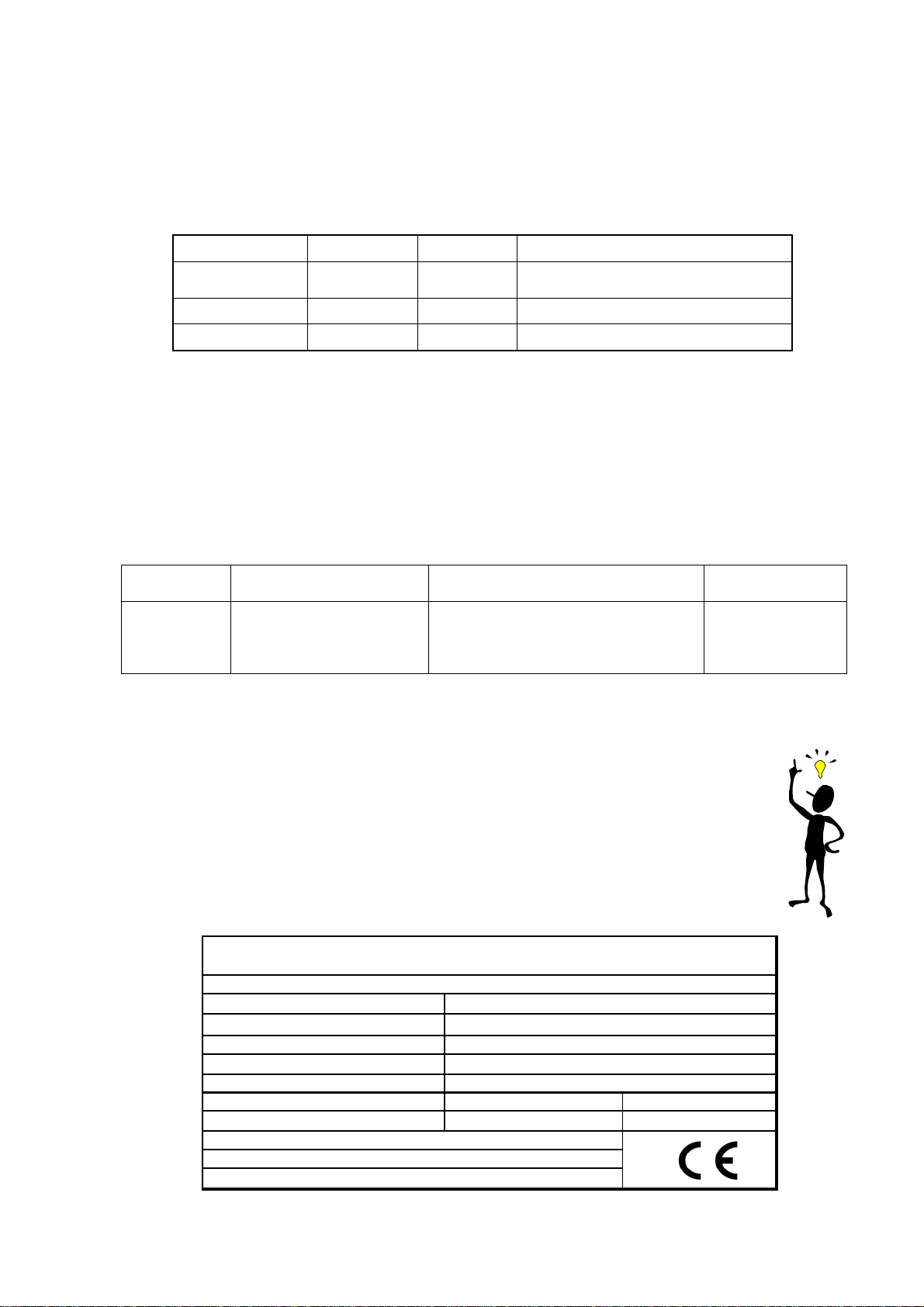
manuals.online logo
Brands
  1. Home
  2. •
  3. Brands
  4. •
  5. Haas+Sohn
  6. •
  7. Indoor Fireplace
  8. •
  9. Haas+Sohn Opus 186.18/1-AL User manual

Haas+Sohn Opus 186.18/1-AL User manual

1
Complete product information, „HAAS+SOHN Opus 186.18/1-AL”
Attention! Before installation, removal the transitsupport left and right!
Description of the system for supplying the air needed for combustion:
No. Product no. Description No. Product no. Description
1 Body of the stove 11 Air intake control
2 0618618005300 Door to the combustion
chamber 12 0618618005325 Fitting for the door handle
3 Refractory 13 0618618005327 Door handle (for the door to
the combustion chamber)
4 Wood storage compartment 14 0618018005301 Inspection window
5 0618018005600 Ashpan 15 0618618005218 Door latch screw
6 0618018015002 Supports for the exhaust flue 16 0050500050005 Insulating brick
7 0089000020005 Adjustable feet 17 0087253000095 Door latch
8 Secondary air 18 0088500050005 Socket for the pipe
supplying air from outside
Ø 100
9 0020100130005 Grate 260x152 19 Air duct
10 0050500040005 Plate for diverting the exhaust
Glases angled upwards 20 0618618005064 steel wire rope
21 0618618005036 Lower draft deflection plate
Suitable fuels:
The following fuels are
permitted for use in your
wood burning stove (see
also section 5.1):
Dry, well seasoned,
unadulterated wood and
wood briquettes which
comply with DIN 51731.
Prod. nr. 0618618019030
V09 E 26
2
Nennwärmeleistung
Zugelassener Brennstoff:
Staub bez.auf 13% O2:28mg/Nm³ Wirkungsgrad: 81,7% CO:0,08%
Prüf Nr. VKF: 11108 NOx: 93 mg/Nm³ HC: 44 mg/Nm³
Herstellnummer: JI 03 000085
Wärmeleistungsbereich: 4,7 -9,2kW
HAAS + SOHN OFENTECHNIK GMBH
URSTEIN NORD 67 A-5412 PUCH
Kamineinsatz Bauart : EN 13229-W / Zeitbrandfeuerstätte
Typenbezeichnung: Opus 186.18/1-AL
8,0 kW
Holz, Holzbrikett nach -DIN 51731,
Prüfstellenkennziffer: 1625 / Prüf Nr. RRF-29 06 1188
Lesen und befolgen Sie die Bedieungsanleitung!
Mehrfachbelegung des Schornsteins ist zulässig
The system for supplying the air needed for combustion in stove unit type 186.18-AL has three settings: the
primary air is adjusted by means of the air intake control (7). With the handle in position 2 (‘right’) the primary air
I enters through the grate, and the primary air II enters through that area of the combustion chamber which is to
wards the front of the stove. With the handle in position 1 (‘middle’) the primary air I only enters via the grate.
The amount of secondary air is set at an optimum level for the unit to provide the necessary ventilation to keep
the window clean and to provide the necessary air for secondary combustion; it is permanently adjusted for
increased comfort. The pre-heated secondary air flows past the top end of the inspection window (8).
Air intake control Primary air I Primary air II Use:
"right" open open
For use when it is heating up and after
fuel has been added
"middle" shut open In normal operation
"left" shut shut Only for keeping the embers glowing
Connection for providing the air needed for combustion:
In airtight buildings there can be reduction in the oxygen content of the room in which the stove is set up; it must
therefore be ensured that there is adequate ventilation. The stove unit type 186.18-AL therefore offers you the
possibility of drawing in the air needed for combustion from outside. The stove can then be operated without
having to depend on the air within the room. In order to do this the air from outside that is needed for combustion
is supplied by means of a flexible pipe attached to the socket for the pipe (18). It is possible for you to change the
position of the pipe socket to the left, right or rear of the stove unit. The end of the pipe carrying the air must be
located in the open air, or in a well ventilated room situated within the building. Operation of the stove unit in
connection with an air conditioning and ventilation system is permitted. When installing the stove unit in
connection with an automatic air conditioning and ventilation system the end of the pipe supplying the air must not
be located in a room which is connected to this system.
Fuels Amount of fuel Primary air:
air intake control Secondary air
(not adjustable)
Chopped
wood
Wood
briquettes:
2 to 3 pieces of
wood (approx. 2 to 2.5kg)
or 1 wood briquette (2kg)
For approximately 10 minutes: open
(handle to the right),
then operate with the handle in
the middle position
open
The amount of fuel and adjustment of the air intake control:
Lighting, and heating the appliance up: see sections 5.4, 5.5 and 5.6 in the instructions for use of the stove.
Use the gloves provided to protect you against the heat when operating the air intake control.
Before every addition of fuel, the air intake control is to be closed completely (handle setting ‘left’).
Tip for burning wood: Every time the stove is lit leave the appliance in the ‘right’ position until the
fuel is burning well (around 10 minutes). (This time can vary somewhat depending on the amount of
draught and the pressures involved).
When adding fuel shut the air intake as indicated.
Specification plate:
3
Test number:
Stove unit: Opus 186.18:
RRF Essen RRF-29 06 1188
Fitting the combustion chamber lining for the
HAAS+SOHN Opus 186.18/1-AL
Installation of the combustion chamber liner:
Note: Labels with the short designations are attached to the mounting parts.
1. Install first row: first RSC (rear block centre) (top groove rearward), then rear blocks left and right (top groove
rearward) and front blocks.
2. Insert bottom blocks 1, 2 and 3.
3. Insert ash pan (5) and grate (9).
4. Install second row: rear blocks and lateral blocks.
5. Insert insulating block (16) and draught deflector plates (10+21).
Installation of the insulating block: Insert insulating block (16) with the short edge into the upper sheet steel
groove (see drawing) and let slip into the lower sheet steel groove.
Installation of the draught deflector plate: Insert draught deflector plate (10) slantwise (bevelled corners at the
back) and place it on the lateral sheet steel angles, then lift the front edge and place it on the support plate.
Important: Push the draught deflector plate (10)to the front until the limit stop is reached!
Push the draught deflector plate lower(21)to the back until the limit stop is reached!
Important: After cleaning of the appliance, or before returning it to service, checks must be carried out to ensure
that the baffle plates are in the correct position (see diagram).

Other Haas+Sohn Indoor Fireplace manuals

Haas+Sohn Exquisit 182.18-AL User manual

Haas+Sohn

Haas+Sohn Exquisit 182.18-AL User manual

Haas+Sohn SKARNES 0434818700000 Technical Document

Haas+Sohn

Haas+Sohn SKARNES 0434818700000 Technical Document

Haas+Sohn EN13229-W User manual

Haas+Sohn

Haas+Sohn EN13229-W User manual

Haas+Sohn Askja 235.17-AUT Technical Document

Haas+Sohn

Haas+Sohn Askja 235.17-AUT Technical Document

Haas+Sohn ROMA Instruction manual

Haas+Sohn

Haas+Sohn ROMA Instruction manual

Haas+Sohn KUOPIO 265.17-PD Paradiso User manual

Haas+Sohn

Haas+Sohn KUOPIO 265.17-PD Paradiso User manual

Haas+Sohn Treviso II Technical Document

Haas+Sohn

Haas+Sohn Treviso II Technical Document

Haas+Sohn FIREPLACE INSERT Instruction manual

Haas+Sohn

Haas+Sohn FIREPLACE INSERT Instruction manual

Haas+Sohn DK LAUSITZ easy Instruction Manual

Haas+Sohn

Haas+Sohn DK LAUSITZ easy Instruction Manual

Haas+Sohn Uppsala 269.15-ST User manual

Haas+Sohn

Haas+Sohn Uppsala 269.15-ST User manual

Popular Indoor Fireplace manuals by other brands

Quadra-Fire VOYAGEUR GRAND INSERT GRAND-MBK-AU owner's manual

Quadra-Fire

Quadra-Fire VOYAGEUR GRAND INSERT GRAND-MBK-AU owner's manual

Riello RS 70 Installation, use and maintenance instructions

Riello

Riello RS 70 Installation, use and maintenance instructions

Travis Industries 1750 Wood owner's manual

Travis Industries

Travis Industries 1750 Wood owner's manual

Whalen WMFP60EC-7 manual

Whalen

Whalen WMFP60EC-7 manual

Regency Contura RC500E Owners & installation manual

Regency

Regency Contura RC500E Owners & installation manual

Vermont Castings VFF32LI Installation & operating instructions

Vermont Castings

Vermont Castings VFF32LI Installation & operating instructions

Vexar CEF32M OWNER'S OPERATION AND INSTALLATION MANUAL

Vexar

Vexar CEF32M OWNER'S OPERATION AND INSTALLATION MANUAL

Comfort Glow 000 to 26 OWNER'S OPERATION AND INSTALLATION MANUAL

Comfort Glow

Comfort Glow 000 to 26 OWNER'S OPERATION AND INSTALLATION MANUAL

Valor LEGEND G3.5 installation manual

Valor

Valor LEGEND G3.5 installation manual

Kingsman HBZDV3624 installation instructions

Kingsman

Kingsman HBZDV3624 installation instructions

Dimplex DF2600 Service manual

Dimplex

Dimplex DF2600 Service manual

KAWMET W8 EKO User's manual & warranty card

KAWMET

KAWMET W8 EKO User's manual & warranty card

Ecoflam BLU 700.1 Series Technical data

Ecoflam

Ecoflam BLU 700.1 Series Technical data

Nordpeis PN-SAL01-200 installation manual

Nordpeis

Nordpeis PN-SAL01-200 installation manual

Dynasty Fireplaces Melody Series Installation instructions & operating manual

Dynasty Fireplaces

Dynasty Fireplaces Melody Series Installation instructions & operating manual

Rinnai Arriva Operation and installation manual

Rinnai

Rinnai Arriva Operation and installation manual

EuroLite FL-200 user manual

EuroLite

EuroLite FL-200 user manual

Travis Industries Maverick owner's manual

Travis Industries

Travis Industries Maverick owner's manual

manuals.online logo
manuals.online logoBrands
  • About & Mission
  • Contact us
  • Privacy Policy
  • Terms and Conditions

Copyright 2025 Manuals.Online. All Rights Reserved.