HAEGER 618 MSPe User manual

618 MSPe
Operation Manual

©2015 HAEGER, INC. All rights reserved. No part of this work may be reproduced, copied, adapted, or
transmitted in any form or by any means without written permission from HAEGER, INC. HAEGER, INC
makes no representation or warranties with respect to the contents here of and specifically disclaims
any implied warranties of merchantability or fitness for any particular purpose. Further, HAEGER, INC
reserves the right to revise this publication and to make changes from time to time in the content
hereof without obligation to notify any person of such revision or changes.
TABLE OF CONTENTS
SECTION 1 -
INTR
ODUCTI
ON
------------------------------------------------------------------------------------------------1
Haeger Locations Worldwide -------------------------------------------------------------------------------------------------------------------- 1
EC Declaration of Conformity-------------------------------------------------------------------------------------------------------------------- 2
Statement of Foreseen Use ---------------------------------------------------------------------------------------------------------------------- 3
Safety Information---------------------------------------------------------------------------------------------------------------------------------- 3
Customer Service ----------------------------------------------------------------------------------------------------------------------------------- 3
Responsibilities of the Operator ---------------------------------------------------------------------------------------------------------------- 3
Responsibilities of the Service Technician ---------------------------------------------------------------------------------------------------- 4
Quality of Parts and Fasteners------------------------------------------------------------------------------------------------------------------- 4
Basic Data Sheet ------------------------------------------------------------------------------------------------------------------------------------ 5
Illustrations of Safety Notes---------------------------------------------------------------------------------------------------------------------- 6
SECTION 2 -
INSTALLATION
-------------------------------------------------------------------------------------------------9
Handling----------------------------------------------------------------------------------------------------------------------------------------------- 9
Recommended Safe Work Zone--------------------------------------------------------------------------------------------------------------- 10
Skid Removal--------------------------------------------------------------------------------------------------------------------------------------- 11
Machine Setup------------------------------------------------------------------------------------------------------------------------------------- 12
Main Power Setup -------------------------------------------------------------------------------------------------------------------------------- 14
Machine Operator Basic Controls------------------------------------------------------------------------------------------------------------- 15
Down/Up Footswitch ---------------------------------------------------------------------------------------------------------------------------- 16
Testing of the Electrical Setup ----------------------------------------------------------------------------------------------------------------- 17
Upper Tool Holder -------------------------------------------------------------------------------------------------------------------------------- 19
Lower Tool Holder -------------------------------------------------------------------------------------------------------------------------------- 20
Conductive Mode Setup Procedure ---------------------------------------------------------------------------------------------------------- 21
Non-Conductive Mode Setup Procedure --------------------------------------------------------------------------------------------------- 23

SECTION 3 –HAEGER SAFETY
SYSTEM
---------------------------------------------------------------------------------- 25
Safety Precautions and Warnings------------------------------------------------------------------------------------------------------------- 25
Safety System Description ---------------------------------------------------------------------------------------------------------------------- 26
How the Safety System Works----------------------------------------------------------------------------------------------------------------- 27
Lockout - Tagout ---------------------------------------------------------------------------------------------------------------------------------- 29
Fire Safety Equipment --------------------------------------------------------------------------------------------------------------------------- 30
Safety Awareness & Residual Risks----------------------------------------------------------------------------------------------------------- 31
Safety System Tests ------------------------------------------------------------------------------------------------------------------------------ 34
SECTION 4 –TOUCH SCREEN OPERATION----------------------------------------------------------------------------- 40
Introduction---------------------------------------------------------------------------------------------------------------------------------------- 40
Machine Controls --------------------------------------------------------------------------------------------------------------------------------- 40
Main Screen ---------------------------------------------------------------------------------------------------------------------------------------- 41
Administration------------------------------------------------------------------------------------------------------------------------------------- 42
Load Programs------------------------------------------------------------------------------------------------------------------------------------- 42
MAS (Modular Autofeed System)------------------------------------------------------------------------------------------------------------- 44
Multi-Station --------------------------------------------------------------------------------------------------------------------------------------- 45
Save -------------------------------------------------------------------------------------------------------------------------------------------------- 46
Setting the TPS ------------------------------------------------------------------------------------------------------------------------------------ 47
Single Station Settings --------------------------------------------------------------------------------------------------------------------------- 48
SECTION 5 –OPT
IONS
------------------------------------------------------------------------------------------------------ 50
Laser Part Locating Light
------------------------------------------------------------------------------------------------------------------------ 50
Modular Autofeed System (MAS)------------------------------------------------------------------------------------------------------------- 50
Vacuum Generator ------------------------------------------------------------------------------------------------------------------------------- 50
Turret Insertion Tool ----------------------------------------------------------------------------------------------------------------------------- 50
Universal Crank Assembly ---------------------------------------------------------------------------------------------------------------------- 50
Multishuttle ---------------------------------------------------------------------------------------------------------------------------------------- 50
Positive Stop System ----------------------------------------------------------------------------------------------------------------------------- 51

SECTION 6 –MACHINE MAINTENANCE -------------------------------------------------------------------------------- 54
Maintenance Schedule -------------------------------------------------------------------------------------------------------------------------- 54
Weekly Care and Maintenance---------------------------------------------------------------------------------------------------------------- 55
Schematics and Diagrams----------------------------------------------------------------------------------------------------------------------- 58
Customer Service --------------------------------------------------------------------------------------------------------------------------------- 59
Warranty-------------------------------------------------------------------------------------------------------------------------------------------- 60
SECTION 7 –PARTS
LIST
---------------------------------------------------------------------------------------------------- 61
Main
Ass
emb
ly
------------------------------------------------------------------------------------------------------------------------------------ 62
Hydraulic Cylinder Main Assembly------------------------------------------------------------------------------------------------------------ 64
Sheet Metal ---------------------------------------------------------------------------------------------------------------------------------------- 65
Air Supply ------------------------------------------------------------------------------------------------------------------------------------------- 67
Dual Safety Sensor Assembly------------------------------------------------------------------------------------------------------------------ 68
Upper Tool Holder Assembly------------------------------------------------------------------------------------------------------------------- 70
J-Frame Mount Assembly----------------------------------------------------------------------------------------------------------------------- 71
Standard Lower Tool Holder ------------------------------------------------------------------------------------------------------------------- 72
Turret Insertion Tool ----------------------------------------------------------------------------------------------------------------------------- 73
Electrical
Cabinet
--------------------------------------------------------------------------------------------------------------------------------- 74
HMI Assembly ------------------------------------------------------------------------------------------------------------------------------------- 76
Hydraulic Reservoir Assembly ----------------------------------------------------------------------------------------------------------------- 77
Hydraulic Manifold Subassembly ------------------------------------------------------------------------------------------------------------- 79
Return Filter Assembly -------------------------------------------------------------------------------------------------------------------------- 81
Service Tray Assembly --------------------------------------------------------------------------------------------------------------------------- 82
MAS-9 Autofeed (Optional) -------------------------------------------------------------------------------------------------------------------- 83
MAS 350 Autofeed (Optional) ----------------------------------------------------------------------------------------------------------------- 85
Vacuum Generator Assembly (Optional) ---------------------------------------------------------------------------------------------------- 87
Positive Stop Assembly (Optional)------------------------------------------------------------------------------------------------------------ 88

1
SECTION 1 -
INTR
ODUCTI
ON
Congratulations!
You are using a genuine Haeger Hardware Insertion Machine - the industry standard for dependable
fastener insertion.
Haeger, Inc. is widely recognized as the industry leader in the development and implementation of
innovative self-clinching fastener installation technologies. For over thirty years, Haeger engineers have
been designing and building flexible systems for installing practically every kind of self-clinching fastener
into practically every kind of work piece - creating new technologies to help Haeger owners get just
about any job done productively and profitably.
Over the years, Haeger’s innovative tooling and patented quick-change automatic fastener feeding
systems have revolutionized the way the world’s fabricators and manufacturers install hardware.
So whenever your operation faces an insertion challenge, turn to the manufacturer with the most
experience in developing self-clinching fastener insertion solutions. Turn to Haeger.
Haeger Locations Worldwide
Haeger, Inc.
Haeger Europe
Haeger China
811 Wakefield Drive
Textielstraat 18
No.2, Lane 55, Fenggong Rd.
Oakdale, CA 95361
7575 CA Oldenzaal
Malu Town, Jiading District
USA
The Netherlands
201801 Shanghai, PRC
Toll Free: (800) 878-4343
Phone: (209) 848-4000
Phone: +31 541 530 230
Phone: +86 21 5695 4988
Fax: (209) 847-6553
Fax: +31 541 532 400
Fax: +86 21 5695 4388

2
EC Declaration of Conformity
Manufacturer & Address:
Haeger, Inc.
811 Wakefield Drive
Oakdale, California 95361
USA
Authorized to Compile Technical File Contact:
Wouter Kleizen
Haeger Europe
Textielstraat 18
7575 CA Oldenzaal
The Netherlands
We declare under our sole responsibility that the product identified as:
Equipment Name: 618MSPe
Equipment Description: Fastener Hardware Insertion Machine
Model: 618MSPe, High or Low Voltage
Serial Number: 6MSP10..
To which this declaration relates is in conformity with the following standards:
Directives 2006/42/EC, Machinery
Directive 2004/108/EC, Electromagnetic Compatibility
And conformity to relevant directives/standards/and or provisions where appropriate:
EN 349: 1993 +A1:2008
ISO 60204-1: 2006 +A1:2009
ISO 12100-1: 2010
BS EN ISO 4413:2010 BS EN ISO 13849-1: 2012 ISO 12100-2: 2010
EN 953: 1998 +A1:2009
Date of Issue: February 22, 2014
Place of Issue: Oakdale, California 95361
Authorized By:
Wouter Kleizen
Title: President

3
Statement of Foreseen Use
Your Machine is intended for use in an indoor commercial or industrial environment. Factory-authorized
training is made available for operators at the time of installation. The Insertion Logic technology and all
Haeger machines are designed to operate at voltages ranging between 380-480V and at 50/60Hz with no
additional power requirements. Haeger systems do not produce thermal, biological, fire or radiation
hazards etc. Again, Haeger machines are not intended or designed to be used in hazardous or explosive
environments, exposure to outside elements of weather such as freezing, wet, extreme high
temperatures or extreme dusty environments. See your local representative or visit http://haeger.com
for more details.
Safety Information
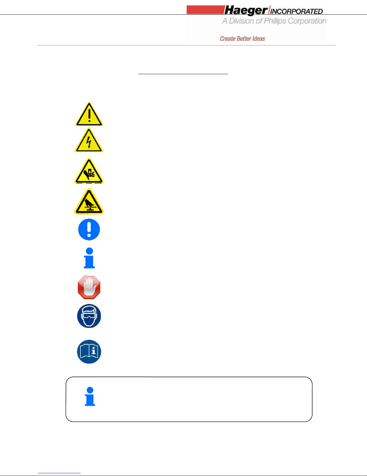
This manual contains details on safety when using your new machine. Cautions and warnings are used
throughout this manual to draw your attention to the different safety precautions. The Haeger Safety
System section of this manual, explains the safety features built into the machine that minimizes the
dangers of pinching or crushing while operating the machine. It is recommended that in addition
the safety details in this Haeger insertion machine manual, all customers, create, implement and maintain
their own individual safety codes, policies and procedures.
Customer Service
If your machine malfunctions and you are unable to resolve the problem, field service technicians can be
dispatched to your site to conduct repairs. Service visits are paid for by the customer, either under a
maintenance agreement, by purchase order or prepayment. Time and material rates are charged for any
service not covered under a maintenance agreement. Before calling to report a problem, gather as much
information about the problem as possible and have it ready to provide to your customer care center.
The more information you can provide initially, the more quickly the problem can be corrected.
Responsibilities of the Operator
The machine operator must be properly trained. Haeger provides training for the operator in the use of
the machine and software at the time of installation. It is the customer's responsibility to ensure that
only properly trained personnel operate the machine. Operators must be fully versed in its operation. For
any operator unfamiliar with its operation, training is required. Training is available; contact your Haeger
representative. The customer must also ensure that all operators are aware of the safety issues
described in this manual. The operator or other trained personnel are expected to handle all user
maintenance as detailed in the User Manual. If your site has a technician in charge of machine
maintenance, that person is the optimal candidate. While any trained operator may perform routine
maintenance, the best maintenance results from familiarity with the machines internal operation and
history. The machine requires daily maintenance to ensure the highest insertion quality and longer life
for the machine. The machine design provides you easy access to perform this simple task and it is
essential that machine maintenance is performed as described in the “Maintenance Schedule”section of
this manual. It is the responsibility of the operator to try to eliminate simple problems before calling a
service representative. But knowing when to call for service is also important. An untrained operator
must not attempt to service the machine as this may cause further damage. When you have determined
that a service call is required, call as soon as possible. See the Troubleshooting and Maintenance
sections for more details.

4
Responsibilities of the Service Technician
Field service technicians must have the Model of Machine and InsertionLogic® (if applicable) service
training. The service technician is responsible for all repairs, upgrading and modification requested by
the customer or mandated by the Haeger Service and Support Group. The service technician who
installs the machine will also provide training for the operator that covers all of the basic skills and
safety practices required to operate the machine. Service personnel must be furnished with proper
tools for the installation and maintenance of the machine.
Quality of Parts and Fasteners
Your machine is designed and engineered for high volume installation of self-clinching fasteners of all
types and sizes. As a rule, the “quality”of parts and fasteners is very important to getting the most out
of your Haeger Insertion Machine. The next two paragraphs are general in nature but critical to
maximizing productivity, quality and profit potential.
Fastener Quality Basics: In general, self-clinching fasteners are designed with an annular recess in the
shank that allows the softer metal of your part (work piece) to cold form in and around it and
permanently lock the fastener in place. Inspecting the fasteners on a regular basis and verifying they are
constructed with in design tolerances is very important. With studs and stand-offs, this is especially
critical as they increase in length. We highly recommend coordination between yourself and the fastener
supplier to determine the acceptable dimensional tolerances and force requirements for your particular
application in an effort to achieve consistent quality.
Part Quality Basics: Take special care in inspecting all parts in which the fasteners will be inserted.
Verify the holes in the part meet the required specifications and tolerances. In addition, visually inspect
each part, looking for burrs and irregularities around each hole. Holes out of tolerance, burrs and
irregularities will degrade the fastener’s performance and may cause difficulties during the insertion
process. We also recommend developing a consistent method of handling or holding the part (work
piece) during the insertion process to ensure quality and increase fastener performance long term.
Self-clinching fasteners should be tested to be sure they meet
manufacturer’s published performance data or specifications specific
to the application.

5
Dimensions
Height:
84 in./2,134 mm
Width:
33 in./838 mm
Depth:
43 in./1,092 mm
Weight:
1,285 lb./583 kg
Basic Data Sheet
Your Machine Model 618MSPe
Serial Number: Year Manufactured:
Voltage: Amperes:
Hertz (Machine): 50/60 Hertz (MAS): 50/60
Phase: 3
618MSPe Machine Matrix
Voltage
208/220
380/480
575
Amperage
8
4
3
Hertz
50 or 60
50 or 60
50 or 60
Phase
3
3
3
Noise Measurement Summary
Emissions Noise Sensitivity
Maximum Measured Value
In normal operation
A weighted pressure level
87dB
C weighted pressure level
87dB
For all locations, noise protection is always recommended
Fluids & Pressure
Hydraulic Oil:*
Hydraulic Oil, ISO 32 Viscosity
Grade
ISO Viscosity:
32
Capacity:
10 gallons/38 liters
Max.
Operating
Pressure:
2,950 psi/203 bar
* Equivalent hydraulic oils may be used. It is the
machine owner’s responsibility to determine which
hydraulic oils in their area are equivalent to ISO 32.

6
Illustrations of Safety Notes
Safety notes are identified by a pictogram and a signal word. The signal word describes the severity of
the risk at hand.
Warning possible dangerous situation that could cause minor
physical injuries.
Risk of electrical voltage possible dangerous situation that could
cause serious physical injuries.
Risk of crush injuries possible dangerous situation that could cause
serious physical injuries.
Risk of pinching injuries possible dangerous situation that could
cause serious physical injuries.
Important for a special behavior or activity for the safe handling of
the machinery.
Application tips and particularly useful information.
Stop! Contact your Haeger Representative for instructions on how to
proceed.
Eye protection must be worn when operating this machine
Read First! Read instructions first before operating this machine.
Make sure that you read and understand all of the descriptions,
instructions and notes contained in this section. Follow all of the
Warnings and Cautions in this manual. Your safety and
productivity
depend on
it.
Your machine was designed to conform to applicable CE, ANSI, OSHA,
and CSA safety standards. It is the user’s responsibility to understand
any specific local safety codes that may require additional guarding
and conform to those standards.

7
Details of Location in the Documentation
All information in these instructions concerning direction and location refer to the workplace of the
operator.
Rear side of machine
Left Side Right
Front side
In this manual, the use of the terms left and right refers to the
machine operator’s left and right when they are standing in
front of the machine, facing the work area between the Upper
Tool
Eye protection must be worn when operating this machine

8
Safety Precautions and Warnings
Never
Operate this Haeger Hardware Insertion Machine without proper
instructions. Read and thoroughly understand this manual before
attempting to operate this machine.
Never
Tamper with any part of this machine’s electrical system unless
you are a trained electrician and thoroughly understand this
machine’s electrical schematic.
Never
Never
Operate this machine while wearing any metal objects (i.e., rings,
watches, bracelets, etc.) that may come into contact with the
Upper Tool, Lower Tool or work piece.
Attempt to test or demonstrate this machine’s Safety System by
placing any portion of your hand or body between the Upper and
Lower tools. Always use the test procedure outlined in Section 4
of this manual.
Never Exceed the maximum force of 9,000 pounds on the J- Frame,
Square Tip Tool Holder, or Positive Stop.
Never
Attempt to run any irregular shaped sheet metal part that could
contact the Upper and Lower Tools before these tools insert the
fastener into the part. This applies to both the Conductive and
Non- Conductive Modes of operation.
Never Press the Down Footswitch a second time in the Non- Conductive
Mode when your hands are in the area of the tooling.
Never Operate this Machine without wearing the proper eye protection
Eye protection must be worn when operating this machine
The Safety System’s heavy duty retractable electrical cord is very durable;
however caution should be taken when working close to the edge of deep
boxes or cans. Operating with the Safety System’s electrical cord too close
to sharp metal edges may damage the cord.
Lubricate the Upper Tool Holder with a small amount of lithium (white)
grease. Any other lubricant may interfere with the Safety System’s
operation and will void your machine warrant

9
SECTION 2 -
INSTALLATION
Handling
The Haeger Hardware Insertion Machine is designed to provide the operator with a comfortable
working height and to allow freedom of movement when positioning work pieces in the tooling
area. Because of these features, the machine is top heavy when unloading.
Handle with extreme caution!
Never attempt to move the machine with a forklift
positioned in front of or on either side of the machine.
Always position the forklift or pallet truck to the rear of
the machine when moving the machine with a forklift or
pallet truck.
NEVER lift machine from
the FRONT or the SIDE, either
IN OR OUT OF THE BOX.
ALWAYS position the
forklift to REAR of the machine.
Machine is HEAVY in REAR
and will tilt back when lifted
with strap

10
Recommended Safe Work Zone
It is recommended that prior to delivery, the customer layout an area in their facility that allows the
operator and maintenance personal, ample space to work or service the machine. The distances
shown below are recommendations. It is the customer’s responsibility to adjust the “Safe Work
Zone”based on their own individual needs to optimize operator and service technician safety. We
also recommend that the customer and/or operator inform facility visitors of the “SAFE WORK
ZONE” around the machine to minimize or eliminate the possibility of accidental bumping of the
operator while the machine is in operation.
RECOMMENDED MINIMUM SAFE WORK ZONE
* The overall Safe Work Zone Dimensions will vary depending on the size of the part or work piece you
are producing. It is generally recommended to have a 3’ (1 m) to 4’(1.22 m) minimum safe zone beyond
the operator and work piece to maneuver the part into position ready for insertion(s). In addition, the
Safe Work Zone provides ample space for the service technician to service the machine.

11
Skid Removal
The feet are already installed on the machine.
You will need to lift the machine to remove the skids.
You will need to open three wrenches to adjust the feet.
Skid Bolt: 9/16 in/13mm socket 9/16”/13mm socket wrench
Foot: 7/8 in/22 mm open end wrench 7/8 in/22 mm
15/16 in/24 mm open end wrench 15/16 in/24 mm
1. Uncrate the machine.
2. Remove the (8) lag screws that hold the machine base to the shipping skid (2 on each plate).
3. Use the strap on the top of the machine frame and an appropriate sling for the weight of this
machine and lift it until it clears the skids.
The weight of the Haeger Hardware Insertion Machine and skids are as follows:
Machine
Pounds
Kilograms
618MSPe
1,285 lb.
583 kg.
4. Carefully move the machine away from the skids (or move the skids). Lower the machine onto the
floor.
5. Lower the nut on the foot and remove the plate.
6. Tighten the foot nut until it is flush with the bottom of the machine’s base.

12
Machine Setup
1. Carefully locate the machine in the shop on a flat and preferably level hard surface such able to
with withstand the weight of the machine as described it the “Basic Data”paragraph of this
manual. If there is any question on the ability of the sub-surface to support the weight of the
machine, check with a structural engineer. As of this publication there are no know
requirements for fixing or anchoring the machine to the sub-surface, check with your local
building code official, agency or structural engineer in your area to verify.
2. Level it front to back and left to right using the top surface of the Lower Tool Holder as a
reference surface (see Figure below) Using a 7/8 in/22 mm wrench to adjust the feet, level the
machine left to right and front to back. Make sure that all of the machine’s feet are securely
resting on the shop floor.
3. Without changing the height adjustment of the feet, tighten the lock nut on each foot using a
15/16in/24mm wrench.
Level the machine
by using the Lower
Tool Holder as a
reference surface.

13
Machine Setup (Continued)
4. For the Model Machines with Modular Auto Feed System (MAS) installed, air must be connected to
the fitting on the black hose which extends down from the bottom of the MAS. Connect an air-line
that is capable of delivering of clean, dry air. For further instructions, reference the Modular Auto
Feeder Operation Maintenance Manual Section of this manual.
Air Flow
Air Pressure
3 ft.3/min - 85 l/min
90 psi/6 Bar
5. If the machine is not yet filled with oil, remove the sides of the machine. Fill the machine with AW
Exxon Humble Hydraulic H or equivalent premium hydraulic oil. Replace the sides when finished.
Fill the reservoir of the machine with the amount of hydraulic oil listed below:
Machine
Gallons
Liters
618MSPe
10
38
Right side and left side panels can be removed to
access Hydraulics.

14
Main Power Setup
The electrical connections required in this section must be
made by a qualified electrician.
Check to make sure that the electrical power supply for this machine
has been disconnected at the supply source before doing any work on the
machine’s electrical system.
1. Check the voltage on the Machine Nameplate, located on the rear of the machine’s Main
Electrical Cabinet (see Figure 2.3)
MAKE SURE the machine’s incoming shop voltage is the same as the voltage the machine
has been wired for. If the voltages do not match
STOP! Contact your Haeger Representative for instructions on how to proceed.
2. Ensure that the machine’s electrical power supply has been disconnected at the supply
source. Turn the machine’s Main Disconnect Switch to the Off position. Using the special key,
open the door of the Main Electrical Control Cabinet (see Figure 2.4).
3. Wire the incoming three phase electrical power to the three connectors on the Main
Disconnect Switch terminals labeled L1, L2 and L3. Make sure the machine is properly
grounded by connecting the incoming ground wire to the top terminal of the green and yellow
terminal block on the right side of the Main Disconnect Switch.
4. After all electrical connections have been properly made, we recommend installing service
loops and/or an angle bracket (not included) on the main power cord coming in through the
rear of the machine. Service loops provide a means of securing the main power cord to the
electrical cabinet. In addition, it provides strain relief and unnecessary wire chafing.
5. Close and latch the Main Electrical Control Cabinet door using the special key.
6. Install the computer into the front of the computer cabinet and secure with fasteners
supplied.
Machine Name
Plate
Turn Off
Po
wer
!
2. Unlock Door
3. Open Cabinet
Figure 2.4 Figure 2.3
Open the door of the Main Electrical Check the voltage on the
Control Cabinet. Machine Nameplate

15
Machine Operator Basic Controls
All the operator controls are located within the HMI Touch Screen, except the foot pedal, the E-Stop
button.
Touch Screen Control Panel
This is the primary interface to the operation control system. It is used for most of the machine’s settings and functions.
You will use the touch screen to enter information. The screen displays text and graphical information and allows the
operator to make selections by touching different parts of the screen as indicated by what is displayed on the screen.
E-Stop Push Button
The E-Stop Push Button switch is used to shut the machine off in all situations. It is a two position switch with a red
mushroom button. When pushed in, it latches, turns the machine’s controls off and shuts down the machine’s motor.
In the In position, the machine cannot be restarted. To restart the machine, twist the red mushroom button
clockwise. There is an arrow showing the direction on the mushroom button. The mushroom button will snap out and
the machine can be restarted.
Machine Power ON / Off Switch
The On Switch is located on the touch screen. When the On/Off Switch is touched, the machine’s controls are turned
on and the motor starts. The switch then will also have a green indicator on the screen showing the machine is turned
on. When the indicator is red, the machine’s controls are off and the motor is stopped.
The Foot Pedal
Switches are used by the operator to control the start of an insertion.
Main Disconnect
Switch
This switch controls power for all machine components (including the touch screen). Rotate clockwise to switch ON and
counterclockwise to switch OFF.

16
Down/Up Footswitch
The Down/Up Footswitch is shielded and connected to the Haeger Hardware
Insertion Machine by a heavy duty cable. It contains both the Down and Up Footswitches.
When the Down Footswitch is depressed, the Upper Tool Holder moves down. If you remove your foot
from the Down Footswitch, the Upper Tool Holder will stop. If you depress the Down Footswitch again,
the downward motion will start again.
Conductive Mode Display Non-Conductive Mode Display
In Conductive Mode, the Hardware Insertion Machine will complete one normal cycle of the insertion
process when the Down Footswitch is depressed and held down. Hold the Down Footswitch until the
Upper Tool Holder starts to go up again.
In the Non-Conductive Mode, when the Down Footswitch is depressed, the Hardware Insertion
Machine will lower the Upper Tool until it contacts the work piece and then stop. The Down Footswitch
must then be released. When the Down Footswitch is depressed a second time, the Hardware
Insertion Machine will exert the preset force and then return to its Up position. Once the upward
travel starts, release the Down Footswitch.
When the Up Footswitch is depressed, the Upper Tool Holder moves up. If you remove your foot from
the Up Footswitch, the Upper Tool Holder will stop. If you depress the Up Footswitch again, the
upward motion will start again.
M
a
k
e sure
yo
u
re
ad and understand the
W
arning and Safety Instructions in the
I
n
tr
odu
ct
ion section of this manual and follow the instructions for testing the
Safety System in the Safety System section b
efore
attempting to operate this
Hardware Insertion Machine.
Never depress the down footswitch a second time in Non-Conductive Mode when your
Hands are in the tooling area.
Table of contents
Popular Power Tools manuals by other brands

Hitachi
Hitachi FCJ 65V3 Handling instructions

CMT ORANGE TOOLS
CMT ORANGE TOOLS Industrio User and maintenance manual

Northern Industrial
Northern Industrial 150609 instruction manual

Bosch
Bosch GRG 18V-16 C Professional Original instructions

Festool
Festool PF 1200 E Original instructions

Bosch
Bosch EXACT 2 Original instructions