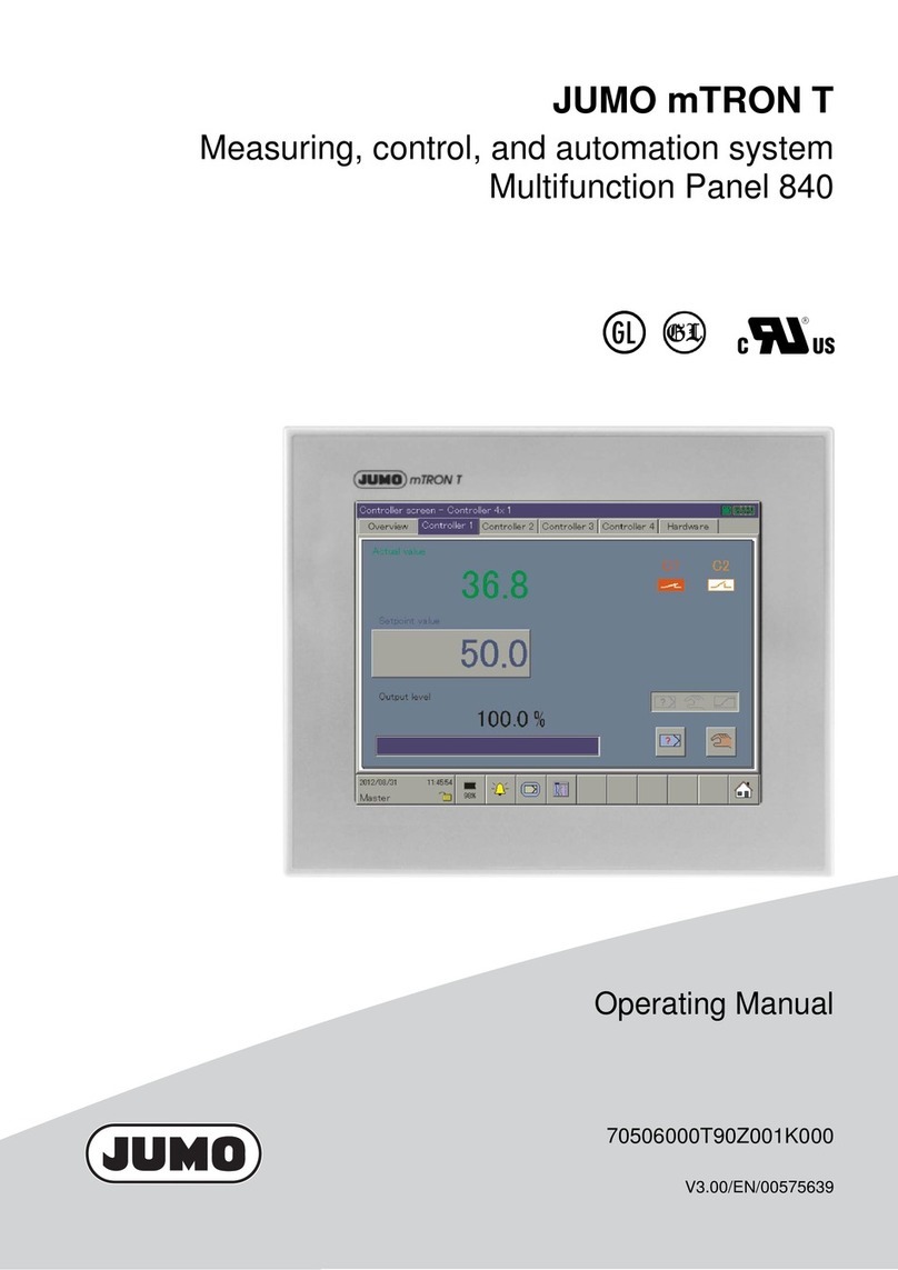
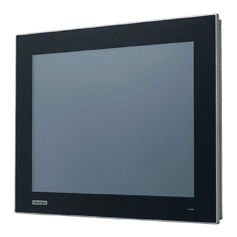
hager h3+ HTD210H User manual


Technical changes reserved 3
Safety symbols 5
Safety information 6
Disposal and recycling information 7
1 About this manual 9
2 The HTD210H Panel display 11
2.1 Components overview 12
2.2 Menu functions 15
2.3 Technical characteristics 16
2.4 Dimensions and cut-outs 17
2.5 Cables and accessories 18
3 Connecting and powering the HTD210HPaneldisplay 19
3.1 Connecting the HTD210HPaneldisplay 20
3.2 Connecting the power supply 21
3.3 First power-up 24
4 Display modes and navigation 25
4.1 Navigation 25
4.2 Start-up screen 27
4.3 Live mode 28
4.4 Main menu 30
4.5 Locked/Unlocked mode 32
4.6 Alarm warnings 34
5 Protection menu 37
5.1 Submenus 37
5.2 Navigation and modifying setting 38
5.3 Submenu contents 39
6 Measure menu 41
6.1 Submenus 41
6.2 Navigation within the Measure menu 43
6.3 Setting favourites and representation 44
6.4 Measurements Settings 46
7 Alarms menu 49
7.1 Submenus 49
7.2 Navigation and setting 51
7.3 Submenu contents 57
8 Configuration menu 59
8.1 Submenus 59
8.2 Navigation and setting 61
8.3 Submenu contents 62
Contents

4Technical changes reserved
9 Information menu 65
9.1 Submenus 65
9.2 Navigation in submenu MCCB information 66
9.3 Navigation in History of alarm events and History of trip events 67
9.4 Submenus contents 68
10 Assistance 69

Technical changes reserved 5
Safety symbols
Safety symbols
This documentation contains safety instructions you have to observe for your
personal safety or for prevention of damage to property.
The safety instructions referring to your personal are notified in the documentation by
a safety alert symbol. The safety instructions referring to property damage are notified
by the mention NOTICE.
The safety alert symbols and mention shown below are classified according to the
degree of danger.
DANGER
DANGER indicates an imminently hazardous situation, which, if not avoided, will re-
sult in death or serious injury.
WARNING
WARNING indicates a potentially hazardous situation, which, if not avoided, could
result in death or serious injury.
CAUTION
CAUTION indicates a potentially hazardous situation, which, if not avoided, may re-
sult in minor or moderate injury.
Warning of property damage
This user manual contains instructions that you must observe to prevent property
damage:
NOTICE
NOTICE indicates a property damage message.
NOTICE also indicates important user notes and especially useful information on the
product to which special attention shall be given so as to have the subsequent activ-
ities performed eectively and safely.

6Technical changes reserved
Safety information
Safety information
Qualified personnel
The product or system described in this documentation should be installed, operated,
and maintained only by qualified personnel.
No responsibility is assumed by Hager Electro for any consequences arising out of
the use of this material.
Qualified personnel are those who have skills and knowledge related to the
construction and operation of electrical equipment and its installation, and who have
received safety training to recognize and avoid the hazards involved.
Proper use of Hager products
Hager products should only be used for the applications described in the catalogue
and in the relevant technical documentation. If products and components from other
manufacturers are used, these must be recommended or approved by Hager. Proper
transport, storage, installation, assembly, commissioning, operation and maintenance
are required to ensure that the products operate safely and without any problems.
The permissible ambient conditions must be complied with. The information in the
relevant documentation must be observed.
Disclaimer of Liability
The contents of this documentation have been reviewed to ensure consistency with
the hardware and software described. Since variance cannot be precluded entirely,
Hager cannot guarantee full consistency. However, the information in this publication
is reviewed regularly and any necessary corrections are included in subsequent
editions.
Technical changes reserved 7
Disposal and recycling information
You must dispose of the HTD210H Panel display properly according to local laws and
regulations. Because it contains electronic components, the Panel display must be
disposed of separately from household waste.
According to local laws and regulations your Panel display product shall be disposed
of separately from household waste. When this product reaches its end of life, take
it to a collection point designated by local authorities. The separate collection and
recycling of your product and/or its battery at the time of disposal will help conserve
natural resources and ensure that it is recycled in a manner that protects human
health and the environment.

8Technical changes reserved

Technical changes reserved 9
About this manual
1 About this manual
Document scope
This document provides information about configuration and operation of the
HTD210H Panel display.
Validity scope
This document is applicable to the HTD210H Panel display for the use with h3+
Energy Moulded Case Circuit Breakers (MCCBs) for monitoring and for setting
applications.
Procedural instructions
Procedural instructions with a fixed order are displayed in clearly arranged tables:
Key Step/Action Screen
Touch
key
1 Procedural instruction step 1
- Result of first action
Display view
Touch
key
2 Procedural instruction step 2
- Result of second action
Display view
Touch
key
3 Procedural instruction step 3
- Result of third action
Display view
Recommendation
The HTD210H Panel display can only be connected with h3+ Energy Moulded Case
Circuit Breakers.
Applicability note
This manual is intended for the following technician groups:
- Panel builders and electrical installers
- System commissionning engineers and integrators
- Service and maintenance personnel
Revisions
Revision No. Date
1.00 05/2018

10 Technical changes reserved
About this manual
Related documents
Document title Reference
HTD210H Panel display installation instruction 6LE002194A
h3+ Moulded Case Circuit Breakers up to 250 A Technical
catalogue 6LE005047A
h3+ Communication System manual 6LE002998A
HTP610H h3+ Configuration tool user manual 6LE003137A
Contact
Address: Hager Electro SAS
132 Boulevard d’Europe
67215 Obernai
France
Phone: + 33 (0)3 88 49 50 50
Fax: + 33 (0)3 88 49 51 44
Website: www.hager.com

Technical changes reserved 11
The HTD210H Panel display
2 The HTD210H Panel display
The HTD210H Panel display is an accessory for the Energy MCCB range. It allows the
full monitoring of the Energy MCCB including the setting and configuration of its trip
unit.
The HTD210H Panel display is mainly intended for visualising measurements, defining
protection settings and managing alarms.
The HTD210H Panel display is usually mounted in the door of a switch cabinet or at a
panel where the connected Energy MCCB is installed.
Various adaptors, each with a certain cable length, allow the HTD210H Panel display
to be mounted within easy reach of the observer. For example, several units can be
mounted at one panel.
Compared to the embedded display of the Energy MCCB, the HTD210H Panel
display has extended access functionalities.
It can visualise most of the Energy MCCB measurements additionally to the 20
measurements covered by the embedded display of the Energy MCCB.
The HTD210H Panel display also allows managing alarms and visualising log events
(Trips and alarms) which is not possible with the embedded display of the Energy
MCCB.

12 Technical changes reserved
The HTD210H Panel display
2.1 Components overview
Display part Description
1Screen LCD screen
2LEDs Alarm - Communication - Ready
3RJ9 connector On the back of device.
4 Contextual key Functionality depends on the displayed menu.
5 left / OK / right key Left and right navigation between menus.
OK: Confirming entries (Enter).
6 back key One step back or exit the current menu.
By holding the key the display changes to Live
mode.
7 up / down key Up and down navigation between menus and
submenus.
Navigation
The navigation through the menus is done using the touch keys at the front of the
product.
NOTE
Do not press the keys, just touch the surface slightly.

Technical changes reserved 13
The HTD210H Panel display
Display
The Display provides dierent screen views, depending on the corresponding
functions:
Display Menu
Main Menu
Alarm pop-up
Live mode
Menu (e.g. Measure)
Standby function
By default the backlight of the display is always on. It can be deactivated in the
Configuration menu. If the standby function is activated, the backlight switch on after
touching any key. In case of high priority alarm during standby, the display switches
on and an alarm pop up is displayed.

14 Technical changes reserved
The HTD210H Panel display
LEDs
LED Description Behaviour
Alarm with medium and high priority. red blinking
Communicating with the Energy MCCB. yellow blinking
The device is supplied with power and is ready. green
External ports
External port Description
Screen Data connection with the Energy MCCB system and power supply
(RJ9 connector).

Technical changes reserved 15
The HTD210H Panel display
2.2 Menu functions
Overview of the available menu functions of the HTD210HPanelDisplay.
Screen Menu Functions
Live mode Standard view of the display
- Visualisation of selected
measurements (favourites).
Main menu - Accessing the menus.
Measure - Visualisation of all measurements.
- Setting the representation of the
measurements.
Protection - Management of the Protection
settings.
Alarms - Management of alarms
(Custom, PreTrip, Trip, OAC).
Configuration - Setting the screen.
- Setting date and time.
- Changing the password.
- Measurements settings.
- Resetting min/max measurement
values.
- Erasing Trip and Alarm events.
Information - Visualisation of trip events and
alarm events.
- Visualisation of technical
information from the connected
Energy MCCB and the HTD210H
Panel display.

16 Technical changes reserved
The HTD210H Panel display
2.3 Technical characteristics
Electrical Characteristics
Rated supply voltage DC 24 V (+/- 30 %) SELV
Consumption 85 mA
Environmental and mechanical Characteristics
Operating temperature range -10 °C…+55 °C
Storage temperature -20 °C…+70 °C
Degree of pollution 2
Installation category III
IP rating of front side IP65
IP rating of back side IP20
Mechanical protection (front face) IK07
Physical characteristics
Dimensions W x H x D 97 x 97 x 46 mm
Panel/Door cut-out dimension 92 x 92 mm
Weight 165 g
Screen dimension 37 x 78 mm
Connector type RJ9
Cable length max 10 m

Technical changes reserved 17
The HTD210H Panel display
2.4 Dimensions and cut-outs
Dimensions Width (mm) Height (mm) Depth (mm)
HTD210H 97 97 18 (45)
Panel cut-out 92 92 up to 8

18 Technical changes reserved
The HTD210H Panel display
2.5 Cables and accessories
Power supply by CIP Power supply by COM module
1CIP 24 V Adaptor
2CIP Adaptor for h3+
3COM module Modbus RTU h3+ without I/O
Reference Description Length (m)
HTC140H CIP 24 V Adaptor 1.2
HTC310H COM module Modbus RTU h3+ without I/O -
HTC320H COM module Modbus RTU h3+ with I/O -
HTC330H CIP Adaptor for h3+ 0.5
HTC340H CIP Adaptor for h3+ 1.5
HTC350H CIP Adaptor for h3+ 3.0
HTC360H CIP Adaptor for h3+ 5.0
HTC370H CIP Adaptor for h3+ 10.0

Technical changes reserved 19
Connecting and powering the HTD210H Panel display
3 Connecting and powering the HTD210HPaneldisplay
DANGER
Risk of electric shock
Danger to life, risk of injury due to electric shock, or risk of serious injury.
¾Make sure that the device is installed only by a qualified electrician
according to the installation standards in force in the country.
NOTICE
Risk of damaging the HTD210H Panel display
Using a wrong adaptor may result in damaging the device.
¾Only connect the RJ9 connector (Display) of the HTD210H Panel display to
an Energy MCCB using an original Hager HTC3XXH CIP Adaptor.

20 Technical changes reserved
Connecting and powering the HTD210H Panel display
3.1 Connecting the HTD210HPaneldisplay
1CIP socket
2CIP connector of the CIP-Adaptor
3CIP-Adaptor
4RJ9 plug of the CIP Adaptor
Step Action
1 Switch the connected Energy MCCB into the “OFF” or “tripped” position.
NOTE
The front cover of the MCCB can only be opened in the “OFF” or “tripped“ position.
2 Open the front cover of the Energy MCCB.
3 Insert the CIP connector of the CIP Adaptor into the CIP socket.
NOTICE
Risk of damaging plug and socket.
- Observe the orientation of the connector.
- Do not force to push the connector into the plug.
4 Lead the cable outside the MCCB.
- Make sure not to pinch the cables.
5 Lead the cable to the HTD210H Panel display.
6 Connect the RJ9 plug of the CIP Adaptor to the socket named “Display” on the back
of the HTD210H Panel display.
Table of contents