ESA AUTOMATION EW3 Series User manual

IT Istruzioni per installazione
EN Installation manual
FR Instructions pour l’installation
DE Installationsanweisung
ES Instrucciones para instalación
CN 安装手册
EW3 SERIES
INDUSTRIAL MONITOR
1
E
W
3
1
5
A
2
E
W
3
1
5
B
3
E
W
3
1
5

4
E
W
3
2
2
A
5
E
W
3
2
2
B
6
E
W
3
2
2

7
E
W
3
.
.
A
1 2
8
E
W
3
.
.
A
23
1
FRONT
BACK
9
E
W
3

1
0
E
W
3
.
.
A
ED FA B C
1
1
E
W
3
.
.
B
A B C D
1
2
E
W
3
AAUTO
MENU
C
E
B
D
1
3
E
W
3
Power supply 4 pins connectors
1 +24 VDC
2 0 VDC
3 Not Connected
4 Protective ground
1
4
E
W
3
~
+- 24V
3
+24V
PE
0V
EW3xx
DEVICE
PE
N
L1
4
1
2
1
5
E
W
3
~
+-
24V
PE
N
L1
~
-
24V
+
PE
N
L1

1
6
E
W
3
SERIAL TOUCH 1 N.C.
2 TXD OUT
3 RXD IN
4 N.C.
5 Signal GND
6 +5V OUT
7 N.C.
8 +VCC IN
Db 9 female connector 9 N.C.
1
7
E
W
3
VGA 1 RED 9 N.C.
2 GREEN 10 N.C.
3 BLUE 11 ISP-SDA
4 ISP-SCL 12 VGA-SDA
5 GND 13 VGA HSYNC
6 RED GND 14 VGA VSYNC
1
6
11
7 GREEN GND 15 VGA SCL
Db 15 female connector 8 BLUE GND
1
8
E
W
3
DVI-D Single Link 1 TX2- 11 GND 21 N.C.
2 TX2+ 12 N.C. 22 GND
3 GND 13 N.C. 23 TXCLK+
4 N.C. 14 VCC 24 TXCLK-
5 N.C. 15 DVI-DET C1
N.C.
6 DDC CLK 16 HP DETECT C2 N.C.
7 DDC DATA 17 TX0- C3
N.C.
8 N.C. 18 TX0+ C4
N.C.
18
916
17 24
C1 C2
C3 C4
C5
9 TX1- 19 GND C5 GND
Dvi 29 female connector
10 TX1+ 20 N.C.

1
9
E
W
3
USB FRONT 1 USBVCC (OUT)
2 USBD-
12
34
3 USBD+
4 pin female connector 4 Signal GND
2
0
E
W
3
USB TOUCH 1 USBVCC (OUT)
2 USBD-
12
34
3 USBD+
4 pin female connector 4 Signal GND
2
1
E
W
3

2
2
E
W
3
RxD
TxD
GND
3
2
5
TxD
RxD
GND
3
2
6
8
5
+5V
VCC
PC COM SERIAL TOUCH
D-SUB
9 PIN FEMALE
D-SUB
9 PIN MALE
Max. 15m.

IT_Italiano
AVVERTENZA
IMPORTANTE: leggere
attentamente queste
istruzioni prima della
installazione del prodotto.
Dimensioni e forature
EW315A – Fig. 1 . 3
EW315B – Fig. 2 . 3
EW322A – Fig. 4 . 6
EW322B – Fig. 5 . 6
Vista frontale
EW3xxA – Fig. 7
1) Porta seriale USB.
2) Power led.
Legenda:
! Spento - Alimentazione non
presente.
! Acceso GIALLO - Alimentazione
presente ma manca segnale
video.
! Acceso VERDE –
Funzionamento regolare.
Vista posteriore
EW3xxA – Fig. 10
A) USB FRONT: Porta per remotare
USB frontale.
B) USB TOUCH: Porta USB per Touch
Screen.
C) SERIAL TOUCH: Porta RS232 per
Touch Screen.
D) DVI-D (single link): Porta DVI per il
collegamento della scheda video
del PC.
E) VGA: Porta CRT per il
collegamento della scheda video
del PC.
F) Alimentazione.
EW3xxB – Fig. 11
A) USB TOUCH: Porta USB per Touch
Screen.
B) DVI-D (single link): Porta DVI per il
collegamento della scheda video
del PC.
C) VGA: Porta CRT per il
collegamento della scheda video
del PC.
D) Alimentazione.
ATTENZIONE: Si consiglia di
utilizzare una sola porta per
collegare il touch screen (Serial
Touch oppure Usb Touch).
IMPORTANTE: Per il collegamento
mediante Serial Touch utilizzare
esclusivamente un cavo come da
schema allegato (Fig. 22)
L’utilizzo di qualunque altro tipo
di cavo può danneggiare
l’apparecchiatura.
Tastierino OSD
EW3 - Fig. 12
A) Consente la regolazione automatica
del monitor / Confermare le scelte.
B) Consente di richiamare a video il
menù.
C) Consente di spostarsi nel menù a
video / Aumentare valore.
D) Consente di spostarsi nel menù a
video / Diminuire valore.
E) Accensione Monitor.
Cavi di collegamento
Per limitare al massimo l’influenza
dei disturbi è necessario utilizzare
cavi schermati di buona qualità.
Caratteristiche del cavo di
collegamento seriale:
! Resistenza in corrente continua -
Max. 151 Ohm/Km
! Accoppiamento capacitivo -
Max. 29pF/m
! Schermatura > 80% oppure
Totale
In ogni caso:
! Cercare il percorso più breve.

! Effettuare la posa separata da
cavi disturbati e/o cavi di
potenza.
! Utilizzare connettori con gusci
metallici o di plastica conduttiva.
Collegare la schermatura del cavo
seriale attenendosi alle indicazioni
riportate in Fig. 21.
NOTA: La calza deve risultare
connessa elettricamente sia al
corpo connettore che al coperchio.
Lo schermo del cavo deve risultare
connesso elettricamente sia alla
custodia che al corpo del
connettore stesso da ambo i lati del
cavo.
Installazione in atmosfera
potenzialmente esplosiva
Per l’utilizzo del EW3xxA in
ambiente ATEX occorre applicare
l’apposito KIT in dotazione al
prodotto. Per ulteriori dettagli vedi
apposito manuale a corredo del
prodotto.
ATTENZIONE: la piastrina di
chiusura DEVE essere montata
PRIMA dell’installazione in ambiente
ATEX.
Attenersi alle indicazioni riportate
in Fig. 8.
1. Rimuovere la guarnizione dal
supporto di protezione
2. Applicare la guarnizione sulla
parte posteriore della piastrina
di chiusura USB.
3. Aprire completamente il tappo
di gomma e applicare con le
apposite viti la piastrina di
chiusura USB.
4. Richiudere il tappo di gomma.
Installazione EW3
EW3 – Fig. 9
Coppia serraggio 1,24 Nm (11 lbs.
in.) +/- 5%
Alimentazione
Significato dei pin del connettore di
alimentazione - Fig. 13.
Collegamento consigliato - Fig. 14.
ATTENZIONE: queste due
configurazioni danneggiano
gravemente il EW3 - Fig. 15.
IMPORTANTE: La massa dei
dispositivi collegati alle porte di
comunicazione seriali e/o
parallele deve essere
tassativamente allo stesso
potenziale dello 0V di
alimentazione del EW3. La
circolazione di una corrente tra lo
0V di alimentazione e la massa
delle porte di comunicazione
potrebbe causare il
danneggiamento di alcuni
componenti del EW3 o dei
dispositivi ad esso collegati.
Temperatura di esercizio
0 / +50°C
Compatibilità
elettromagnetica
Restrizioni d’uso: i requisiti di
protezione non sono assicurati in
zone residenziali.
Impostazione parametri di
setup
a. Eseguire tutti i collegamento
mantenendo il monitor spento.
b. Avviare il monitor.
c. Avviare il PC.
d. Caricare i driver del touch screen
(solo EW3xxA).

e. Assicurasi di avere impostato le
seguenti risoluzioni:
! EW315 - 1366x768
! EW322 - 1920x1080
Porte di comunicazione
Fig. 16 . 17 . 18 . 19 . 20
Pulizia della superficie
Per la pulizia del EW3 si consiglia di
utilizzare Alcool Etilico Denaturato.
Certificazioni
Tutti i prodotti descritti in questo
manuale sono conformi ai seguenti
standard:
compatibilità elettromagnetica
(EMC):
! emissioni EN 61000-6-4
(2007)
! immunità EN 61000-6-2
(2005)
e perciò rispondono a:
Council Directive
EMC 2004/108/EC
EN_English
WARNING
IMPORTANT: Please read
carefully these instructions
before mounting the product.
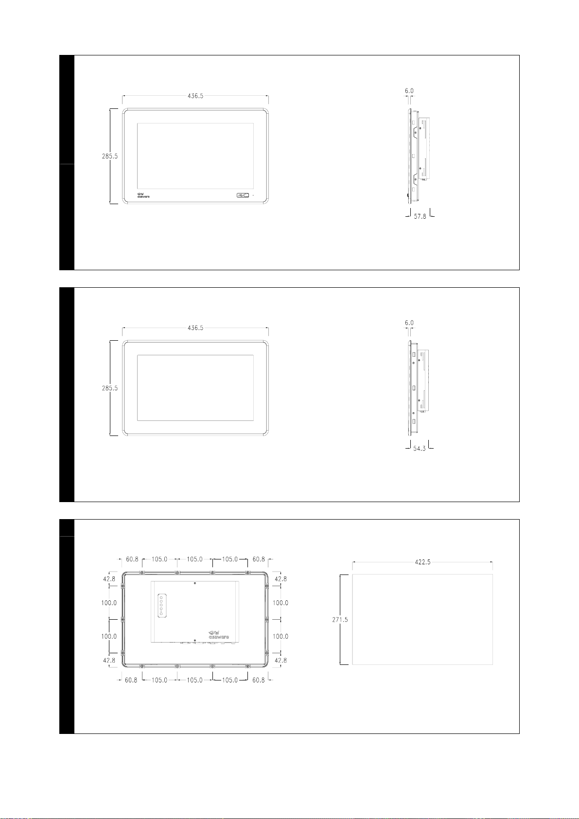
Dimensions and holes
EW315A – Fig. 1 . 3
EW315B – Fig. 2 . 3
EW322A – Fig. 4 . 6
EW322B – Fig. 5 . 6
Front view
EW3xxA – Fig. 7
1) Universal Serial Bus port.
2) Power led.
Legend:
! Off - No power source.
! YELLOW On - Power present
but no video signal.
! GREEN On - Functioning
correctly.
Rear view
EW3xxA – Fig. 10
A) USB FRONT: Port to remote front
USB.
B) USB TOUCH: USB port for Touch
Screen.
C) SERIAL TOUCH: RS232 port for
Touch Screen.
D) DVI-D (single link): DVI port for
connecting with PC graphics board.
E) VGA: CRT port for connecting with
PC graphics board.
F) Power supply.
EW3xxB – Fig. 11
A) USB TOUCH: USB port for Touch
Screen.
B) DVI-D (single link): DVI port for
connecting with PC graphics board.
C) VGA: CRT port for connecting with
PC graphics board.
D) Power supply.

WARNING: It is advisable to use
only one port to connect the touch
screen (Serial Touch or USB
Touch).
IMPORTANT: For connection by
means of Serial-Touch, use only a
cable as shown in the attached
layout (Fig. 22).
Use of any other type of cable
may damage the equipment.
OSD keypad
EW3 - Fig. 12
A) Allows the automatic regulation of
the monitor / Confirm selections.
B) Allows you to display the menu.
C) Allows you to move within the on-
screen menu / To increase the
value.
D) Allows you to move within the on-
screen menu / To decrease the
value.
E) Turning on the Monitor.
Connection cables
In order to limit as much as
possible the influence of these
disturbances good quality shielded
cables must be used.
Specifications of serial connection
cable:
! Direct current resistance - Max.
151 Ohm/Km
! Capacity coupling - Max.
29pF/m
! Shielding > 80% or total
Always:
! Find the shortest route.
! Lay disturbed cables separately.
! Use connectors with metal or
conduc-tive plastic shells.
Connect the serial cable shield in
accordance with the instructions on
Fig. 21.
NOTE: The braiding must be
electrically connected both to the
connector body and shell. The
interface cable braiding must be
electrically connected both to the
shell and the body of the connector
at both ends of the cable.
Installation in potentially
explosive atmospheres
When EW3xxA is intended for use
in ATEX environment, the attached
ATEX KIT must be used and
properly applied. For further details
see the ATEX manual supplied with
the product.
WARNING:the closing plate must
be fixed before the EW3xx is
installed in ATEX environment.
Please follow the instructions by
Fig. 8.
1. Remove the gasket from
protective support.
2. Apply the gasket on the rear
side of the closing plate for the
USB port.
3. Open completely the rubber
USB cover, insert the closing
plate in the USB hole and fix the
plate by using the proper
screws.
4. Close the rubber USB cover
Installing the EW3
EW3 – Fig. 9
Tightening Torque 1,24 Nm (11 lbs.
in.) +/- 5%
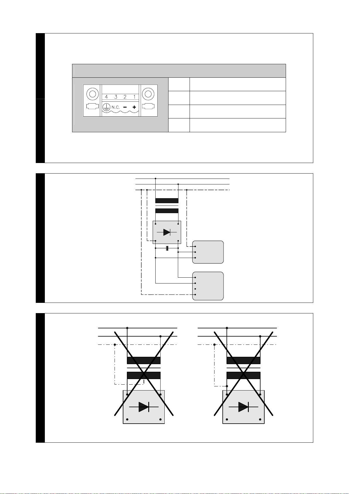
Power supply
Power connector pin-out - Fig. 13.
Recommended power connection -
Fig. 14.

WARNING: These two
configuration will seriously damage
components - Fig. 15.
IMPORTANT: The earth of the
devices connected to the serial
and/or parallel communication
ports MUST have the same
potential as the 0V supply of the
EW3. The circulation of current
between the 0V supply and the
earth of the communication ports
could cause damage to certain
components of the EW3 or of the
devices connected to it.
Working temperature
0 / +50°C
Electromagnetic
compatibility
Restriction of use: protection
requirements are not ensured in
residential areas.
Entering set-up parameters
a. Carry out all connections with the
monitor off.
b. Start-up the monitor.
c. Start up PC.
d. Load touch screen drivers
(EW3xxA only).
e. Check that EW has been set with
resolution of:
! EW315 – 1366x768
! EW322 – 1920x1080
Communication ports
Fig. 16 . 17 . 18 . 19 . 20
Cleaning
For cleaning the EW3 we
recommend Denaturalised Ethyl
Alcohol.
Certifications
All the products described in this
manual comply with the following
standards:
electromagnetic compatibility
(EMC):
! emissions EN 61000-6-4
(2007)
! immunity EN 61000-6-2
(2005)
and thus are in line with:
Council Directive
EMC 2004/108/EC

FR_Français
AVERTISSEMENT
IMPORTANT : lire
attentivement ces
instructions avant
l’installation du produit.
Dimensions et perçage
EW315A – Figure . 1 . 3
EW315B – Figure . 2 . 3
EW322A – Figure . 4 . 6
EW322B – Figure . 5 . 6
Vue frontale
EW3xxA – Figure . 7
1) Port Universal Serial Bus.
2) Power led.
Légende :
! Eteint - Absence d'alimentation.
! JAUNE allumé - Présence
d'alimentation mais absence de
signal vidéo.
! VERT allumé - Fonctionnement
régulier.
Vue postérieure
EW3xxA – Fig. 10
A) USB FRONT: Port pour mettre à
distance USB frontal.
B) USB TOUCH: Port USB pour Ecran
Tactile.
C) SERIAL TOUCH: Port RS232 pour
Ecran Tactile.
D) DVI-D (single link): Port DVI pour le
raccordement de la carte vidéo du
PC.
E) VGA: Port CRT pour le
raccordement de la carte vidéo du
PC.
F) Alimentation.
EW3xxB – Fig. 11
A) USB TOUCH: Port USB pour Ecran
Tactile.
B) DVI-D (single link): Port DVI pour le
raccordement de la carte vidéo du
PC.
C) VGA: Port CRT pour le
raccordement de la carte vidéo du
PC.
D) Alimentation.
ATTENTION :Nous conseillons
d'utiliser un seul port pour brancher
l'écran tactile (Serial Touch ou bien
Usb Touch).
IMPORTANT : Pour le
raccordement au moyen du Serial
Touch utiliser exclusivement un
câble comme illustré dans le
schéma ci-joint (Figure. 22).
L'utilisation de tout autre type de
câble peut endommager
l'appareillage.
Claveir OSD
EW3 - Fig. 12
A) Permet le réglage automatique de
l'écran / Confirmer les choix.
B) Permet de rappeler à l'écran le
menu.
C) Permet de se déplacer dans le
menu à l'écran / Augmenter la
valeur.
D) Permet de se déplacer dans le
menu à l'écran / Diminuer la valeur.
E) Allumage Ecran.
Câbles de raccordement
Pour limiter au maximum l’influence
de ces parasites il faut utiliser des
câbles blindés de bonne qualité.
Caractéristiques du câble de
raccordement sériel :
! Résistance en courant continu -
Max. 151 Ohm/Km
! Accouplement capacitif - Max.
29pF/m
! Blindage > 80% ou bien total

Dans tous les cas :
! Chercher le parcours le plus
bref.
! Effectuer la pose séparée des
câbles perturbés.
! Utiliser des connecteurs du type
spécial à carcasse avec gaines
métalliques ou en plastique
conductible.
Raccorder le blindage du câble
sériel en se tenant strictement aux
indications reportées dans Figure .
21.
NOTE : La gaine doit être
connectée électriquement au corps
du connecteur et à son habillage.
La protection du câble d’interface
doit résulter électriquement
connectée aussi bien à la gaine
qu’au corps du connecteur luimême
des deux côtés du câble.
Installation en atmosphères
explosibles
Pour utiliser l’EW3xxA dans un
environnement ATEX il faut
appliquer le kit spécifique livré avec
la produit. Pour de plus amples
informations, se référer au manuel
fourni avec le produit.
ATTENTION : le couvercle de
fermeture doit être monté avant
l’installation dans un environnement
ATEX
Suivre les indications données sur
la Figure . 8.
1. Retirer le joint du support de
protection
2. Appliquer le joint sur la partie
postérieure du couvercle de la
porte USB.
3. Ouvrir complètement le
bouchon en caoutchouc et fixer
avec les vis le couvercle de la
porte USB.
4. Remettre en place le bouchon
en caoutchouc.
Installation du EW3
EW3 – Figure . 9
Couples de serrage 1,24 Nm (11 lbs.
in.) +/- 5%
Alimentation
Signification des pins du
connecteur d’alimentation - Figure .
13.
Connexion conseillée - Figure . 14.
ATTENTION : Ces deux
configurations peuvent
endommager certains composants
- Figure . 15.
IMPORTANT : La masse des
dispositifs connectés aux ports de
communication parallèles ou
sériels doit formellement être au
même potentiel qu’il 0V
d’alimentation du EW3. La
circulation d’un courant entre il
0V d’alimentation et la masse des
ports de communication pouvait
causer des dommages aux
composants du EW3 ou des
dispositifs connectés.
Température d’exercice
0 / +50°C
Compatibilité
électromagnétique
Restriction d'emploi: les protection
n'est pas assurée dans les zones
résidentielles.
Chargement des paramètres
de setup
a. Exécuter tous les raccordements en
maintenant l'écran éteint.
b. Allumer l'écran.
c. Lancer le PC.

d. Charger les driver de l'écran tactile
(seulement EW3xxA).
e. S'assurer d'avoir réglé le EW avec
résolution :
! EW315 - 1366x768
! EW322 - 1920x1080
Portes de comunication
Figure . 16 . 17 . 18 . 19 . 20
Nettoyage
Pour nettoyer le EW3 est conseillé
d’utiliser de l’Alcool Éthylique
Dénaturé.
Certifications
Tous les produits décrits dans ce
manuel sont conformes aux
standards suivants :
compatibilité electromagnétique
(EMC) :
! émissions EN 61000-6-4
(2007)
! immunité EN 61000-6-2
(2005)
et ils répondent pour cela aux :
Council Directive
EMC 2004/108/EC
DE_Deutsch
HINWEIS
WICHTIG: lesen Sie die
Hinweise sorgfältig durch
bevor Sie Installationen
durchführen.
Maße und Ausschnitt
EW315A – Abbildung . 1 . 3
EW315B – Abbildung . 2 . 3
EW322A – Abbildung . 4 . 6
EW322B – Abbildung . 5 . 6
Vorderansicht
EW3xxA – Abbildung . 7
1) Universelles serielles Busanschluß.
2) Power LED.
Zeichenerklärung:
! Abgeschaltet - Keine
Stromversorgung.
! GELB eingeschaltet -
Stromversorgung anwesend
aber kein Videosignal.
! GRÜN eingeschaltet -
Funktioniert richtig.
Rückansicht
EW3xxA – Abbildung . 10
A) USB FRONT: Remote - Schnittstelle
Frontal - USB.
B) USB TOUCH: USB - Schnittstelle für
Touch Screen.
C) SERIAL TOUCH: RS232 -
Schnittstelle für Touch Screen.
D) DVI-D (single link): DVI-
Schnittstelle für den Anschluss mit
dem Grafikboard.
E) VGA: CRT-Schnittstelle für den
Anschluss mit dem Grafikboard.
F) Versorgung
EW3xxB – Abbildung . 11
A) USB TOUCH: USB - Schnittstelle für
Touch Screen.

B) DVI-D (single link): DVI-
Schnittstelle für den Anschluss mit
dem Grafikboard.
C) VGA: CRT-Schnittstelle für den
Anschluss mit dem Grafikboard.
D) Versorgung
ACHTUNG: Es ist ratsam, für die
Verbindung des Touch Screens nur
eine Schnittstelle zu verwenden
(Serial-Touch oder auch USB-
Touch).
WICHTIG: Für eine Serial Touch -
Verbindung ausschließlich die im
Schaltschema angegeben Kabel
verwenden (Abbildung . 22).
Die Verwendung einer anderen
Kabelart kann das Gerät
beschädigen.
OSD Tastatur
EW3 - Abbildung . 12
A) Ermöglicht die automatische
Regelung des Monitors / Die
Bestätigung der Auswahl.
B) Gestattet die Anzeige des Menüs.
C) Gestattet Bewegung innerhalb des
angezeigten Menüs / Wert erhöhen.
D) Gestattet Bewegung innerhalb des
angezeigten Menüs / Wert
verringern.
E) Einschalten des Monitors.
Schnittstellenkabel
Da die serielle Kommunikation
extrem anfällig für Störungen ist,
müssen zur Vermeidung dieser
Störungen qualitativ hochwertige
abgeschirmte Leitungen verwendet
werden.
Empfehlungen für serielle
Schnittstellenkabel:
! Gleichstromwiderstand - Max.
151 Ohm/Km
! Kapazitive Kopplung - Max.
29pF/m
! Abschirmung > 80% oder
Komplettschirmung
In jedem Fall:
! Leitungen auf dem kürzesten
Weg verlegen.
! Datenleitungen getrennt von
Lastleitungen verlegen.
! Steckergehäuse aus Metall oder
leitfähigem Kunststoff
verwenden.
Die Abschirmung des seriellen
Kabels den Anweisungen der
Abbildung. 21 entsprechend
vornehmen.
Bemerkung: Das Schirmgeflecht
muß elektrisch sowohl mit dem
Steckerkörper als auch mit dem
Gehäuse verbunden sein.
Installation in
explosionsgefährdete
Umgebung
Um die EW3xxA Familie in eine
explosionsgefährdete Umgebung
zu verwenden, muß der spezielle,
mit dem Produkt gelieferte
Installationssatz, eingesetzt
werden. Details siehe separate
Installationsanleitung.
ACHTUNG: Die Abdeckung muss
vor dem Einbau in eine
explosionsgefährdete Umgebung
wieder aufgesetzt werden.
Folgen Sie den Anweisungen aus
Abbildung . 8.
1. Entfernen Sie die Dichtung.
2. Befestigen Sie die Dichtung auf
der Rückseite der USB
Deckplatte.
3. Öffnen Sie die Gummidichtung
vollständig und befestigen Sie es
auf der USB Verriegelungsplatte.

4. Gummidichtung wieder
einsetzen.
EW3-Installation
EW3 – siehe Abbildung . 9
Anziehdrehmoment 1,24 Nm (11 lbs.
in.) +/- 5%
Spannungsversorgung
Anschluß des Versorgungssteckers
- siehe Abbildung . 13.
Empfohlene Verdrahtung - suehe
Abbildung . 14.
WARNUNG: Diese beiden
Anschlussarten führen zu Schäden
am EW3 Gerät - siehe Abbildung .
15.
WICHTIG: Die Erde der parallelen
und/oder seriellen Datenleitung
müssen das gleiche Potential
führen wie die Erde der
Spannungsversorgung vom
Bediengerät. Eine nicht korrekte
Erdung der Spannungsversorgung
und der Datenleitungen können
schwere Schäden an den
Bediengeräten sowie an den
angeschlossene Komponenten
hervorrufen.
Betriebstemperatur
0 / +50°C
Elektromagnetische
Verträglichkeit
Nutzungsbeschränkung: Die
Störfestigkeit für Wohnbereiche ist
nicht gegeben.
Eingabe der
Einrichtungsparameter
a. Alle Anschlüsse bei
ausgeschaltetem Monitor
ausführen.
b. Den Monitor einschalten.
c. PC starten.
d. Laden Sie die Touch-Screen-
Treiber(nur für EW3xxA).
e. Kontrollieren Sie, dass die EW -
Auflösung:
! EW315 - 1366x768
! EW322 - 1920x1080
Schnittstellen-Anschlüsse
Abbildung . 16 . 17 . 18 . 19 . 20
Reinigung der Touch-
Oberfläche
Für die Reinigung der Touch
Oberfläche wird die Verwendung
von Ethylalkohol empfohlen.
Zertifizierungen
Alle im vorliegenden Handbuch
beschriebenen Produkte sind
konform mit den folgenden
Standards:
elektromagnetische Kompatibilität
(EMC):
! Emissionen EN 61000-6-4
(2007)
! Störimmunität EN 61000-6-2
(2005)
und entsprechen daher den:
Council Directive
EMC 2004/108/EC

ES_Español
ADVERTENCIA
IMPORTANTE: leer estas
instrucciones con cuidado
antes de la instalación
producto.
Dimensiones y perforaciones
EW315A – Fig. 1 . 3
EW315B – Fig. 2 . 3
EW322A – Fig. 4 . 6
EW322B – Fig. 5 . 6
Vista frontal
EW3xxA – Fig. 7
1) Puerto Bus de Serie Universal.
2) Power led.
Leyenda:
! Apagado - Alimentación
ausente.
! Encendido AMARILLO -
Alimentación presente pero falta
señal vídeo.
! Encendido VERDE -
Funcionamiento regular.
Vista posterior
EW3xxA – Fig. 10
A) USB FRONT: Puerto para gestión
remota USB frontal.
B) USB TOUCH: Puerta USB para
Pantalla Táctil.
C) SERIAL TOUCH: Puerto RS232 para
Pantalla Táctil.
D) DVI-D (single link): Puerto DVI para
la conexión de la tarjeta vídeo del
PC.
E) VGA: Puerto CRT para la conexión
de la tarjeta vídeo del PC.
F) Alimentación
EW3xxB – Fig. 11
A) USB TOUCH: Puerta USB para
Pantalla Táctil.
B) DVI-D (single link): Puerto DVI para
la conexión de la tarjeta vídeo del
PC.
C) VGA: Puerto CRT para la conexión
de la tarjeta vídeo del PC.
D) Alimentación
ATENCIÓN: Se aconseja utilizar un
solo puerto para conectar la
pantalla táctil (Serial Touch o Usb-
Touch).
IMPORTANTE: Para la conexión
mediante Serial Touch utilizar
exclusivamente un cable como en
el esquema adjunto (Fig. 22).
El uso de cualquier otro tipo de
cable puede dañar el equipo.
Teclado OSD
EW3 - Fig. 12
A) Permite la regulación automática
del monitor / Confirmar lo elegido.
B) Permite visualizar el menú.
C)
Permite desplazarse por el menú
vídeo / Aumentar valor
.
D)
Permite desplazarse por el menú
vídeo / Disminuir valor
.
E) Encendido Monitor.
Cables de conexión
Para limitar al máximo sus
influencias, es necesario utilizar
cables apantallados de calidad.
Características del cable de
conexión en serie:
! Resistencia en corriente
continua - Máx. 151 Ohm/Km
! Acoplamiento de capacidad -
Máx. 29pF/m
! Apantallado > 80% o tota
En todo caso:
! Busque el recorrido más corto.
! No realice el tendido junto a
cables con perturbaciones.
This manual suits for next models
4
Table of contents
Languages:
Popular Industrial Monitor manuals by other brands


Pepperl+Fuchs
Pepperl+Fuchs VisuNet GMP RM/PC 200 series Hardware manual

Hope Industrial Systems
Hope Industrial Systems HIS-WL19-*A Series user manual

SRScales
SRScales SRV947IFS Operating and service manual

Hitachi
Hitachi UT42X902/D8MW Service manual

Synergy Global Technology
Synergy Global Technology LCDR8U21-03 user manual

Panasonic
Panasonic VF2H Series Construction manual


