Xycom KPM Series User manual

Artisan Technology Group is your source for quality
new and certied-used/pre-owned equipment
• FAST SHIPPING AND
DELIVERY
• TENS OF THOUSANDS OF
IN-STOCK ITEMS
• EQUIPMENT DEMOS
• HUNDREDS OF
MANUFACTURERS
SUPPORTED
• LEASING/MONTHLY
RENTALS
• ITAR CERTIFIED
SECURE ASSET SOLUTIONS
SERVICE CENTER REPAIRS
Experienced engineers and technicians on staff
at our full-service, in-house repair center
WE BUY USED EQUIPMENT
Sell your excess, underutilized, and idle used equipment
We also offer credit for buy-backs and trade-ins
www.artisantg.com/WeBuyEquipment
REMOTE INSPECTION
Remotely inspect equipment before purchasing with
our interactive website at www.instraview.com
LOOKING FOR MORE INFORMATION?
Visit us on the web at www.artisantg.com for more
information on price quotations, drivers, technical
specications, manuals, and documentation
Contact us: (888) 88-SOURCE | sales@artisantg.com | www.artisantg.com
SM
View
Instra

2007XYCOM AUTOMATION, LLC. Printed in the United States of America
KPM(T) Monitor Series
Flat Panel Industrial Monitors
User Manual for the
5012KPM(T) and
5015KPM(T)
models
Artisan Technology Group - Quality Instrumentation ... Guaranteed | (888) 88-SOURCE | www.artisantg.com

KPM(T) Series Flat Panel Industrial Monitor Revision
143448(D)
Revision Description Date
A Manual Released 03/04
B TIR caution added 06/04
C Clarified front panel frame, glass and overlay in Tables 1-1 & 1-2 08/04
D Name change, correct where applicable with document 04/07
Part Number 143448(D)
Trademark Information
Xycom and Xycom Automation are trademarks of Xycom Automation, L.L.C.
Xycom Automation, L.L.C. now is referred to as Pro-face through a D.B.A. The Pro-face name and logo will
replace the Xycom name and logo on all documents where possible.
Pro-face is a trademark of Digital Electronics Corporation.
Brand or product names are trademarks or registered trademarks of their respective owners. Intel and
Pentium are registered trademarks and Celeron is a trademark of Intel Corporation. Windows, Windows NT,
and Windows XP are registered trademarks of Microsoft Corporation in the U.S. and in other countries.
Copyright Information
This document is copyrighted by Xycom Automation, L.L.C. (Xycom) and shall not be reproduced or copied
without expressed written authorization from Xycom Automation, L.L.C.
The information contained within this document is subject to change without notice. Pro-face does not
guarantee the accuracy of the information.
United States FCC Part 15, Subpart B, Class A EMI Compliance Statement:
NOTE: This equipment has been tested and found to comply with the limits for a Class A digital
device, pursuant to part 15 of the FCC Rules. These limits are designed to provide reasonable
protection against harmful interference when the equipment is operated in a commercial
environment. This equipment generates, uses, and can radiate radio frequency energy and, if not
installed and used in accordance with the instruction manual, may cause harmful interference to
radio communications. Operation of this equipment in a residential area is likely to cause harmful
interference in which case the user will be required to correct the interference at the user’s
expense.
For European Users – WARNING:
This is a Class A product. In a domestic environment this product may cause radio interference in
which case the user may be required to take adequate measures.
INSTALLATION – Electromagnetic Compatibility WARNING:
The connection of non-shielded equipment interface cables to this equipment will invalidate FCC
EMI and European Union EMC compliance and may result in electromagnetic interference and/or
susceptibility levels which are in violation of regulations applying to the legal operation of this
device. It is the responsibility of the system integrator and/or user to apply the following directions
relating to installation and configuration:
All interface cables must include shielded cables. Braid/foil type shields are recommended.
Communication cable connectors must be metal, ideally zinc die-cast backshell types, and
provide 360-degree protection about the interface wires. The cable shield braid must be
terminated directly to the metal connector shell; ground drain wires alone are not adequate.
Protective measures for power and interface cables as described within this manual must be
applied. Do not leave cables connected to unused interfaces or disconnected at one end.
Changes or modifications to this device not expressly approved by the manufacturer could
void the user’s authority to operate the equipment..
Artisan Technology Group - Quality Instrumentation ... Guaranteed | (888) 88-SOURCE | www.artisantg.com

i143448 (D)
Table of Contents
CHAPTER 1 – INTRODUCTION ...................................................................................................................................1
PRODUCT OVERVIEW ....................................................................................................................................................1
STANDARD FEATURES ...................................................................................................................................................1
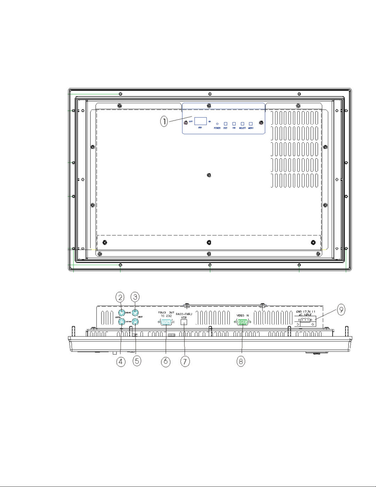
Front Panel Controls ..............................................................................................................................................2
Back Panel.............................................................................................................................................................5
UNPACKING THE UNIT....................................................................................................................................................7
QUICK STARTUP ...........................................................................................................................................................8
CHAPTER 2 – INSTALLATION.....................................................................................................................................9
INSTALLATION OVERVIEW...............................................................................................................................................9
SYSTEM CUTOUT DIMENSIONS .....................................................................................................................................11
5012KPM(T).........................................................................................................................................................11
5015KPM(T).........................................................................................................................................................12
POWER MANAGEMENT.................................................................................................................................................13
System Power......................................................................................................................................................13
Excessive Heat ....................................................................................................................................................14
Electrical Noise ....................................................................................................................................................14
Line Voltage Variation ..........................................................................................................................................15
General Compatibility Issues ...............................................................................................................................15
XVME COMPATIBILITY ISSUES .....................................................................................................................................16
USING A TOUCH SCREEN .............................................................................................................................................16
CUSTOM LOGO ...........................................................................................................................................................17
CREATING CUSTOM KEYPAD INSERTS ...........................................................................................................................17
HAZARDOUS LOCATIONS INSTALLATION .........................................................................................................................23
Safety Agency Approval.......................................................................................................................................24
Definitions ............................................................................................................................................................25
Class I Locations..................................................................................................................................................25
Class II Locations.................................................................................................................................................25
Division 1 Locations .............................................................................................................................................25
Division 2 Locations .............................................................................................................................................26
Groups .................................................................................................................................................................26
Enclosures ...........................................................................................................................................................27
Power Switch .......................................................................................................................................................27
Cable Connections...............................................................................................................................................28
Hazardous Locations Control Drawing.................................................................................................................29
Operation and Maintenance.................................................................................................................................30
CHAPTER 3 – MONITOR SETTINGS .........................................................................................................................31
ON SCREEN DISPLAY (OSD) SWITCH...........................................................................................................................31
MODE AND IMAGE ADJUSTMENT ...................................................................................................................................31
OSD Functions.....................................................................................................................................................32
Reset Factory Default Settings.............................................................................................................................34
ANALOG RGB INTERFACE SPECIFICATIONS ...................................................................................................................34
GRAPHIC MODES ........................................................................................................................................................35
CHAPTER 4 – OPERATOR INPUT.............................................................................................................................36
INSTALLING THE TOUCH SCREEN DRIVER ......................................................................................................................36
CALIBRATING THE TOUCH SCREEN................................................................................................................................37
USING A POINTING DEVICE WITH A TOUCH SCREEN FOR DOS.........................................................................................37
CHAPTER 5 – KEYPAD UTILITY PROGRAM............................................................................................................38
LOADING THE KEYPAD UTILITY .....................................................................................................................................38
USING THE KEYPAD UTILITY .........................................................................................................................................38
STARTUP....................................................................................................................................................................39
MAIN MENU................................................................................................................................................................39
Exit .......................................................................................................................................................................40
Artisan Technology Group - Quality Instrumentation ... Guaranteed | (888) 88-SOURCE | www.artisantg.com

ii 143448 (D)
Files Menu ...........................................................................................................................................................40
Macros Menu .......................................................................................................................................................41
Upload Menu........................................................................................................................................................43
Download Menu ...................................................................................................................................................43
Utilities Menu........................................................................................................................................................44
UTILITY BATCH MODE..................................................................................................................................................44
KEYPAD SCAN CODES .................................................................................................................................................45
CHAPTER 6 – MAINTENANCE ..................................................................................................................................48
GENERAL PREVENTIVE MAINTENANCE...........................................................................................................................48
Fuse Replacement...............................................................................................................................................48
TROUBLESHOOTING.....................................................................................................................................................48
Before Contacting Technical Support...................................................................................................................48
PRODUCT REPAIR PROGRAM .......................................................................................................................................49
KPM(T) SERIES FRONT PANEL FRAME.........................................................................................................................50
Chemicals Compatible with Frame.......................................................................................................................50
Front Panel Overlay .............................................................................................................................................51
Chemicals Compatible with Overlay.....................................................................................................................51
Compatible Cleaning Agents for Overlay .............................................................................................................51
Chemicals Not Compatible with Overlay ..............................................................................................................51
APPENDIX A – TECHNICAL SPECIFICATIONS........................................................................................................52
HARDWARE SPECIFICATIONS........................................................................................................................................52
ENVIRONMENTAL SPECIFICATIONS ................................................................................................................................53
APPENDIX B – PINOUTS ...........................................................................................................................................54
VGA INPUT CONNECTOR.............................................................................................................................................54
SERIAL INTERFACE......................................................................................................................................................54
Touch Screen RS-232 Output Connector ............................................................................................................55
USB INPUT/OUTPUT CONNECTOR................................................................................................................................55
Artisan Technology Group - Quality Instrumentation ... Guaranteed | (888) 88-SOURCE | www.artisantg.com

1143448 (D)
Chapter 1 – Introduction
Product Overview
Pro-face/Xycom industrial flat panel monitors offer state-of-the-art performance
and features while meeting the rigorous requirements of the plant floor. Pro-face/
Xycom’s 5012KPM(T) and 5015KPM(T) high-resolution flat panel displays reflect
the latest technology and are contained within a rugged housing with a resistive membrane
touch screen, an integral pointing device, and an integral full alphanumeric keypad.
The 5012KPM(T) and 5015KPM(T) are UL508 listed, CE compliant and UL listed
for use in Class I & II Division 2 Hazardous Locations.
The front panel is sealed to NEMA TYPE 4/4x/12 (UL 50) standards and is protected
by an impact-resistant shield. UL listed for Hazardous Locations: Class I, Division 2,
Groups A, B, C; Class II, Division 2, Groups F and G (pending).
Standard Features
The KPM(T) monitor comes with the following standard features:
•
••
•
Rear IBM® PS/2 keyboard port and mouse port
•
••
•
Front PS/2 keyboard/mouse port and front USB port
•
••
•
Diagnostic LEDs
– Power
– Input
•
••
•
Analog RGB video interface
•
••
•
Analog resistive touch screen with RS-232 interface
•
••
•
Die-cast aluminum front bezel
•
••
•
Shallow mounting depths – 2.32”on 5012KPM(T) and 2.17” on
5015KPM(T)
•
••
•
100-240V AC or optional 24V DC input power
•
••
•
Front panels meet NEMA 4/4X/12 and IP65 specifications when panel
mounted
•
••
•
UL Listed for use in Class I and Class II, Division 2 Hazardous Locations,
Groups A, B, C, D, F, and G
•
••
•
UL 508 Listed
•
••
•
40 relegendable function keys (74 with the F/A function)
•
••
•
Numeric, PC control, and alpha keypads
•
••
•
Integrated mouse
Artisan Technology Group - Quality Instrumentation ... Guaranteed | (888) 88-SOURCE | www.artisantg.com

KPM(T) Series Flat Panel Industrial Monitor Chapter 1 – Introduction
2 143448 (D)
The 5012KPM(T) has a 12.1" TFT SVGA color LCD, which supports resolutions up
to 800x600 @75Hz. The 5015KPM(T) has a 15” TFT XGA, which supports
resolutions up to 1024x768 @ 75Hz.
The figures and tables on the next several pages illustrate the internal and external
components of the front and back panels to help you locate the features of the
KPM(T) monitors.
Figure 1-1 shows the front panel controls for the KPM(T) monitors. Table 1-1
outlines the front panel control functions.
Figure 1-1. 5012KPM(T)& 5015KPM(T) Front Panel Controls
The 5012KPM(T) and 5015KPM(T) feature function keys on either side of the flat
panel display (PF1-PF20), function keys below the display (F1-F20), a numeric
keypad, window keys, a curser control keypad, power LED, input LED, industrial
Artisan Technology Group - Quality Instrumentation ... Guaranteed | (888) 88-SOURCE | www.artisantg.com

KPM(T) Series Flat Panel Industrial Monitor Chapter 1 – Introduction
3 143448 (D)
mouse/keyboard and USB ports. All keypad keys are reprogrammable1, except the
F/A key, and all function keys are relegendable2. See Chapter 5 for more details.
Caution
Leaving your TFT LCD display on constantly can result in temporary image retention
(TIR). TIR can be avoided by using a screen saver, enabling the idle/doze timeout
feature, or by turning off the display when it is not in use.
Table 1-1. 5012KPM(T) & 5015KPM(T) Front Panel Controls Functions
Feature Description
Front Panel The front panel has four components: a display; strengthened glass
covering the display; a frame in which the display and the glass are
mounted; and the polyester overlay attached to both the glass and the
frame.
The 5012KPM(T) has a 12.1" TFT LCD flat panel. The 5015KPM(T) has a
15" TFT LCD flat panel.
The strengthened glass covering the display is intended to withstand
normal operating conditions. In the event of damage to the glass, the
overlay will protect the user from any glass shards.
For more information abut the frame or the overlay, see Chapter 6 –
Maintenance.
Diagnostic LEDs Following is a description of the diagnostic LEDs and their meanings:
Power GREEN when the system has power.
Disk LED is not active on the 5012KPM(T) and 5015KPM(T).
COM LED is not active on the 5012KPM(T) and 5015KPM(T).
Input GREEN when the unit has a touch screen (LED gets brighter
when a touch input is detected) or a key is pressed.
Fault LED is not active on the 5012KPM(T) and 5015KPM(T).
Brightness Control These buttons adjust the brightness of the backlights. The right button
increases the brightness and the left button decreases the brightness.
Port Access
The 5012KPM(T) and 5015KPM(T) feature front panel access to a PS/2
keyboard/mouse port and a USB 1.1 or 2.0 port (depending on capabilities
of the host).
These front access connections on the 5012KPM(T) and 5015KPM(T)
are nonincendive circuits and may be used safely in Class I Division 2,
Groups A, B, C, & D and in Class II Division 2, Groups F & G
applications in which the peripheral electrical characteristics comply
with the Hazardous Locations Control Drawing on page 29.
1All keypad keys can be programmed to perform any function necessary.
2You are able to create your own, custom keypad inserts to reflect any reprogramming you may have done.
Artisan Technology Group - Quality Instrumentation ... Guaranteed | (888) 88-SOURCE | www.artisantg.com

KPM(T) Series Flat Panel Industrial Monitor Chapter 1 – Introduction
4 143448 (D)
Table 1-1. 5012KPM(T) & 5015KPM(T) Front Panel Controls Functions
Feature Description
74-Key Keypad The 5012KPM(T) and 5015KPM(T) keypads feature:
• Alpha, numeric and control keys
• 40 relegendable function keys
• All keys reprogrammable (except the F/A key)
Integrated Mouse The 5012KPM(T) & 5015KPM(T) feature a 2-button integrated mouse.
See Chapter 5, Keypad Utility Program, for detailed instructions on programming the
keypad. See Chapter 2, Installation, for detailed instructions on creating custom
keypad inserts.
Artisan Technology Group - Quality Instrumentation ... Guaranteed | (888) 88-SOURCE | www.artisantg.com

KPM(T) Series Flat Panel Industrial Monitor Chapter 1 – Introduction
5 143448 (D)
Figure 1-2 shows a view of the KPM(T) monitor back panel. Figure 1-3 shows the
bottom edge of the back panel, where the connectors are located.
Figure 1-2. 5012KPM(T) & 5015KPM(T) Back Panel, straight view
Figure 1-3. 5012KPM(T) & 5015KPM(T) Back Panel, bottom view
The back panel contains the OSD controls, the power connector, a video input
connector, a pass-thru USB port (B-style connector), the serial touchscreen output
connector, and the local and host ports for an external mouse and keyboard. The
input range for the power supply is 100-240 VAC, 50-60 HZ, or 18-32 VDC.
Appendix A contains more information about the power connector pinouts.
Artisan Technology Group - Quality Instrumentation ... Guaranteed | (888) 88-SOURCE | www.artisantg.com

KPM(T) Series Flat Panel Industrial Monitor Chapter 1 – Introduction
6 143448 (D)
Table 1-2. 5012KPM(T) & 5015KPM(T) Back Panel Functions
No.* Feature Description
1 OSD controls Used to access, navigate and execute the OSD
menu. The controls include the selector switch, and
Menu, Select, Increase and Decrease buttons
2 Mouse Local Used to plug in external mouse
3 Mouse Host Used to send both external mouse and integrated
mouse signals to the computer (host), whether the
optional external mouse is plugged into the local
port on the back of the monitor or into the port on
the front of the monitor
4 Keyboard Local Used to plug in external keyboard
5 Keyboard Host Used to send the external keyboard and integrated
keypad signals to the computer (host), whether the
optional external keyboard is plugged into the local
port on the back of the monitor or into the port on
the front of the monitor
6 Touch Out RS-232 Used to send touch screen output to the computer
(host)
7 Pass-Thru USB** Used only as a pass thru port for USB signals to
and from the host
8 Video In (VGA) Used to receive video input signal from computer
(host) VGA port.
9 AC Input (DC option) 100-240 VAC auto-ranging (18-30 VDC on DC
models)
* See diagrams on previous page.
** USB devices plugged directly into this connector will not function.
The OSD controls are explained further in Chapter 3, Monitor Settings.
There must be an external cable connecting the “mouse host” port to the host
computer for the integrated mouse to work. An external mouse can be plugged into
either the front port or the “mouse local” port on the back of the KPM(T) monitor. If
you are using an external mouse, there must be a cable going from the “mouse host”
port to the host computer.
There must be an external cable connecting the “keyboard host” port to the host
computer for the integrated keypad to work. An external keyboard can be plugged
into either the front port or the “keyboard local” port on the back of the KPM(T)
monitor. If you are using an external keyboard, there must be a cable going from the
“keyboard host” port to the host computer.
A Y cable may be used to connect both an external keyboard and an external mouse
to the front port.
Caution
Do not connect either a mouse or keyboard cable from the PS/2 host port to the PS/2
local port. Damage can occur to either the host computer or the KPM(T) monitor.
Artisan Technology Group - Quality Instrumentation ... Guaranteed | (888) 88-SOURCE | www.artisantg.com

KPM(T) Series Flat Panel Industrial Monitor Chapter 1 – Introduction
7 143448 (D)
The Touch Out RS-232 is used when the touch screen option is utilized. A cable in
this port sends the signals from the touch screen to the computer.
There is a USB port on the front of the monitor that can be used at any time. This is a
pass-through only; there is no local USB activity on your KPM(T) monitor. To make
your device work, you must have a cable going out to the computer from the USB
port on the back of the monitor.
Caution
The USB cable that is used to connect the USB device cannot be more than 5 meters in
length from the host computer, or the device will not work correctly. Pro-face ships a
3M USB cable with the 5012KPM(T) monitors and 5015KPM(T) monitors.
As a basic part of the initial setup of your KPM(T) monitor, you will connect a cable
to both the AC port and the Video In port. The cable from the computer to the Video
In port provides the signal connection for the monitor. An RS-232 cable sends touch
screen signals to the computer. A PS/2 cable connected to the ‘host keyboard’ port
sends keypad (or an optional external keyboard) signals to the computer. A PS/2
cable connected to the ‘host mouse’ port sends integral mouse (or an optional
external mouse) signals to the computer.
Unpacking the Unit
When you remove the KPM(T) monitor from its shipping box, verify that you have
the parts listed below. Save the box and inner wrapping in case you need to reship the
unit.
•
••
•
5012KPM(T) or 5015KPM(T) monitor
•
••
•
Documentation kit, which includes
• 10-32 hex nuts (12)
• Analog RGB Cable (10 ft.)
• RS-232C Cable (10 ft.)
• Two PS/2 cables (10 ft.)
• USB Cable (3 m)
• Documentation and Support Library CD-ROM, which contains this manual
and all drivers required by this unit
Artisan Technology Group - Quality Instrumentation ... Guaranteed | (888) 88-SOURCE | www.artisantg.com

KPM(T) Series Flat Panel Industrial Monitor Chapter 1 – Introduction
8 143448 (D)
Quick Startup
This section gives you the steps to get the system up and running without explaining
the capabilities and options.
Warning
Remove power from the unit and disconnect the power cord before making
any adjustments to the inside or outside of the monitor.
Warning
For Hazardous Locations installation, review Hazardous Locations
Installation in Chapter 2 before startup.
To prepare the system for use, perform the following steps.
1. Attach optional keyboard to the keyboard port.
2. Attach optional mouse to the mouse port.
3. Attach other optional equipment following the instructions in Chapter 2.
4. Attach the power cord from the power receptacle to a properly grounded 100-240
VAC, 50-60 Hz, or an optional 18-30 VDC power source. (See System Power in
Chapter 2 for more information.)
5. Turn on power to the KPM(T) monitor (via an outlet power switch if applicable).
Then turn on power to the host computer. The system will boot up into the
operating system.
6. If the unit is equipped with a touch screen, install drivers on the host computer
via the floppy, the CD-ROM, or the network, as applicable.
Artisan Technology Group - Quality Instrumentation ... Guaranteed | (888) 88-SOURCE | www.artisantg.com

9143448 (D)
Chapter 2 – Installation
This chapter offers detailed installation instructions and outlines the options for the
5012KPM(T) & 5015KPM(T). It also includes the guidelines for preparing your unit
for installation and use.
Installation Overview
Warning
For Hazardous Locations installation, review the Hazardous Locations
Installation section in this chapter before startup.
The rugged design of the KPM(T) monitors allows the unit to be installed in most
industrial environments. The system is generally placed in a NEMA 4/4X/12
enclosure to protect against contaminants such as dust, and moisture. Metal
enclosures also help minimize the effects of electromagnetic radiation that nearby
equipment can generate. Class II Hazardous Locations always require a Type 12
(dust-proof) minimum enclosure rating.
Read the following sections carefully to be sure that you are complying with all the
safety requirements.
1. Select a NEMA rated enclosure and place the unit within the enclosure to allow
easy access to the system ports (see other sections in this chapter and Appendix
A).
• To assure a NEMA 4 seal, choose an approved enclosure that has a 14-gauge
(0.075 in/1.9 mm thick steel or 0.125 in/3.2 mm thick aluminum) front face.
• Be sure to account for the unit’s depth when choosing the depth of the
enclosure.
2. Create a cutout in the enclosure (see Figure 2-1 and Figure 2-2 in System Cutout
Dimensions).
• Be sure to place the unit at a comfortable working level
• Make sure the area around the cutout is clean and free from metal burrs
3. Mount the unit in an upright position and properly secure the unit into the panel.
• Tighten the fourteen #10 nuts to 25 inch-pounds (2.8 Newton-meters / 28Kgf
cm).
4. Attach one end of the power cord to the power receptacle on the unit and the
other end to a properly grounded 100-240 VAC, 50-60 Hz outlet, or optional 18-
30 VDC power source.
Artisan Technology Group - Quality Instrumentation ... Guaranteed | (888) 88-SOURCE | www.artisantg.com

KPM(T) Series Flat Panel Industrial Monitor Chapter 2 – Installation
10 143448 (D)
5. Turn on power to the KPM(T) monitor, and then to the host computer. The
system will boot up the installed operating system.
6. Install the application software via a floppy drive, CD-ROM, or the network.
Additional aspects to take into account when mounting your KPM(T) monitor:
•
••
•
Consider locations of accessories such as AC power outlets and lighting
(interior lighting and windows) for installation and maintenance convenience
•
••
•
Prevent condensation by installing a thermostat-controlled heater or air
conditioner
•
••
•
To allow for maximum cooling, avoid obstructing the airflow
•
••
•
Place any fans or blowers close to the heat generating devices. If using a fan,
make sure that outside air is not brought into the enclosure unless a fabric or
other reliable filter is used. This filtration prevents conductive particles and
other harmful contaminants from entering the enclosure.
•
••
•
Do not select a location near equipment that generates excessive
electromagnetic interference (EMI) or radio frequency interface (RFI).
Examples of these types of equipment are: high power welding machines;
induction heating equipment; and large motor starters.
•
••
•
Place incoming power line devices (such as isolation or constant voltage
transformers, local power disconnects, and surge suppressers) away from the
system. The proper location of incoming line devices keeps power wire runs
as short as possible and minimizes electrical noise transmitted to the unit.
•
••
•
Make sure the location does not exceed the unit’s shock, vibration, and
temperature specifications
•
••
•
Install the unit in the rack or panel in such a way as to ensure that it does not
cause a hazard from uneven mechanical loading
•
••
•
Incorporate a readily-accessible disconnect device in the fixed wiring on
permanently connected equipment
•
••
•
Avoid circuit overloading of the supply circuit
Artisan Technology Group - Quality Instrumentation ... Guaranteed | (888) 88-SOURCE | www.artisantg.com

KPM(T) Series Flat Panel Industrial Monitor Chapter 2 – Installation
11 143448 (D)
System Cutout Dimensions
Figure 2-1 shows the cutout dimensions for the 5012KPM(T). Figure 2-2 shows the
cutout dimensions for the 5015KPM(T).
5012KPM(T)
Figure 2-1. 5012KPM(T) system cutout dimensions (inches [mm])
Artisan Technology Group - Quality Instrumentation ... Guaranteed | (888) 88-SOURCE | www.artisantg.com

KPM(T) Series Flat Panel Industrial Monitor Chapter 2 – Installation
12 143448 (D)
5015KPM(T)
Figure 2-2. 5015KPM(T) system cutout dimensions (inches [mm])
Artisan Technology Group - Quality Instrumentation ... Guaranteed | (888) 88-SOURCE | www.artisantg.com

KPM(T) Series Flat Panel Industrial Monitor Chapter 2 – Installation
13 143448 (D)
Power Management
The monitor is based on the VESA DPMS and the DVI DMPM standards. To
activate the monitor's Power Management function, both the video card and the
computer must conform to the VESA DPMS standard and the DVI DMPM standard.
It is a good practice to use isolation transformers on the incoming AC power line to
the system. An isolation transformer is especially desirable in cases in which heavy
equipment is likely to introduce noise onto the AC line. The isolation transformer can
also serve as a step-down transformer to reduce the incoming line voltage to a desired
level. The transformer should have a sufficient power rating (units of volt-amperes)
to supply the load adequately.
Proper grounding is essential to all safe electrical installations. Refer to the relevant
federal, state/provincial, and local electric codes, which provide data such as the size
and types of conductors, color codes and connections necessary for safe grounding of
electrical components. The code specifies that a grounding path must be permanent
(no solder), continuous, and able to safely conduct the ground-fault current in the
system with minimal impedance (minimum wire required is 18 AWG, 1 mm).
Observe the following practices:
• Separate the power and ground (P. E., or Protective Earth) cable from signal
cables at the point of entry to the enclosure. To minimize the ground wire length
within the enclosure, locate the ground reference point near the point of entry for
the plant power supply.
• All electrical racks or chassis and machine elements should be Earth Grounded in
installations where high levels of electrical noise can be expected. The
rack/chassis should be grounded with a ground rod or attached to a nearby Earth
structure such as a steel support beam. Connect each different apparatus to a
single Earth Ground point in a "star" configuration with low impedance cable.
Scrape away paint and other nonconductive material from the area where a
chassis makes contact with the enclosure.
The following figures diagram the power input terminal blocks for the KPM(T)
monitors.
Number Function
1
AC Line Input
2
AC Neutral Input
100-240 VAC
Power Input Terminal Block
3 Protective Earth
Ground
Figure 2-3 100-240 VAC Power Input Terminal Block
Artisan Technology Group - Quality Instrumentation ... Guaranteed | (888) 88-SOURCE | www.artisantg.com

KPM(T) Series Flat Panel Industrial Monitor Chapter 2 – Installation
14 143448 (D)
Number Function
1
+ DC Line Input
2
– DC Return Input
18-30 VDC
Power Input Terminal Block
3 Protective Earth
Ground
Figure 2-4. 18-30 VDC Power Input Terminal Block
Caution
Use 18 AWG (1mm) wire or greater for the monitor power cable
Isolate the AC main circuit line, I/O signal lines, and power cord. Do not
bind or group them together.
To keep the temperature in range, the cooling air at the base of the system must not
exceed the maximum temperature specification (see Environmental Specifications in
Appendix A). Allocate proper spacing between internal components installed in the
enclosure. When the air temperature is higher than the specified maximum in the
enclosure, use a fan or air conditioner to lower the temperature.
Electrical noise is seldom responsible for damaging components, unless extremely
high energy or high voltage levels are present. However, noise can cause temporary
malfunctions that can result in hazardous machine operation in certain applications.
Noise may be present only at certain times, may appear at widely spread intervals, or
in some cases, may exist continuously.
Noise commonly enters through input, output, and power supply lines, and may also
be coupled through the capacitance between these lines and the noise signal carrier
lines. This usually results from the presence of high voltage or long, close-spaced
conductors. When control lines are closely spaced with lines carrying large currents,
the coupling of magnetic fields can also occur. Use shielded cables to help minimize
noise. Potential noise generators include switching components, relays, solenoids,
motors, and motor starters.
Refer to the relevant Federal, State/Provincial, and local electric codes, which
provide data such as the size and types of conductors, color codes and connections
necessary for safe grounding of electrical components. It is recommended that high-
and low-voltage cabling be separated and dressed apart. In particular, AC cables and
switch wiring should not be in the same conduit with all communication cables.
Artisan Technology Group - Quality Instrumentation ... Guaranteed | (888) 88-SOURCE | www.artisantg.com

KPM(T) Series Flat Panel Industrial Monitor Chapter 2 – Installation
15 143448 (D)
The power supply section of the unit is built to sustain the specified line fluctuations
and still allow the system to function within its operating margin. As long as the
incoming voltage is adequate, the power supply provides all the logic voltages
necessary to support the monitor unit.
Unusual AC line variations may cause undesirable system shutdowns. As a first step
to reduce line variations, correct any possible feed problems in the distribution
system. If this correction does not solve the problem, use a constant voltage
transformer. The constant voltage transformer stabilizes the input voltage to the
systems by compensating for voltage changes at the primary in order to maintain a
steady voltage at the secondary. When using a constant voltage transformer, check
that the power rating is sufficient to supply the unit.
!
Listed below are general compatibility issues that apply to the 5012KPM(T) and
5015KPM(T):
•
••
•
The KPM(T) monitor must be powered up before the host computer is
powered up so that the host can determine if a keyboard and mouse are
connected. If the KPM(T) monitor is not powered up first, the host will
determine that there is no mouse or keyboard available.
•
••
•
Once the complete system is up and running, the KPM(T) monitor can be
power cycled at any time without affecting the host. It is the initial power up
of the host that requires the power up sequence.
•
••
•
If an operating system is loaded on the host computer, the KPM(T) monitor
should not be used as the host mouse or keyboard during the loading of the
operating system. Instead, a mouse and keyboard can plug directly into the
host for the loading of an operating system. The KPM(T) monitor can be
used for the monitor only during the loading of the operating system.
•
••
•
The IBM specification for PS/2 ports defines both a Type I and Type II
interface. The KPM(T) monitor is a Type II interface. Pro-face has determined
that not all PS/2 compatible devices are Type II compatible. The user can try
any standard PS/2 device, but Pro-face only guarantees the approved list.
•
••
•
Non-standard devices should not be used with the KPM(T) monitor. If a
device does not meet the standard PS/2 definition, and does not use the
standard PS/2 driver that comes with the operating system, it will not work
reliably with the KPM(T) monitor. For example, if a device requires its own
separate driver it probably will not work because it was written to expect that
the device would be plugged directly into the computer’s host port. In the
case of the KPM(T) monitor, this is not true.
Table 2-1. Known compatible and incompatible devices
Compatible Microsoft®PS/2 Mouse
Logitech® Mouse
Incompatible Dell® Mouse
•
••
•
Daisy-chaining two or more KPM(T) monitors is not supported.
Artisan Technology Group - Quality Instrumentation ... Guaranteed | (888) 88-SOURCE | www.artisantg.com
This manual suits for next models
5
Table of contents
Other Xycom Industrial Monitor manuals
Popular Industrial Monitor manuals by other brands

ROE
ROE Black OnyX3 user manual

Advantech
Advantech IDK-1115WP Series user manual

Prestigio
Prestigio PDSIN55WNN0L quick start guide

Industrial Automation and Enclosures Inc.
Industrial Automation and Enclosures Inc. RLCD170 user manual

Maxell
Maxell MA-8610WH user manual

Eaton
Eaton ELC-GP02 instruction sheet