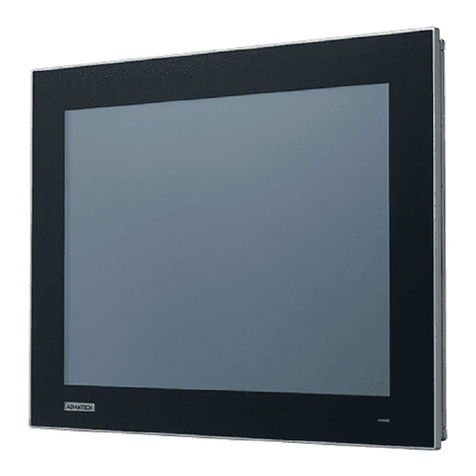
Bosch Rexroth ctrlX HMI DE0015 User manual

ctrlX HMI
DE0015, DE0021
Multi-Touch Displays (Housing Devices)
Operating Instructions
R911405731
Edition 02

ctrlX HMI DE0015, DE0021 Multi-Touch
Displays (Housing Devices)
Change record
Edition 02, 2021-02
Refer to tab. 1-1 "Change record" on page 1
Copyright
© Bosch Rexroth AG 2021
All rights reserved, also regarding any disposal, exploitation, reproduction, edit-
ing, distribution, as well as in the event of applications for industrial property
rights.
Liability
The specified data is intended for product description purposes only and shall
not be deemed to be a guaranteed characteristic unless expressly stipulated in
the contract. All rights are reserved with respect to the content of this documen-
tation and the availability of the product.
Editorial Department
Development Automation Systems Control Platform JüKö (MaKo/MePe)
RS-3e331ada6ac4f7250a347e864ea99674-2-en-US-3

Table of Contents
Page
1 About this documentation..................................................................... 1
1.1 Overview on target groups and product phases.................................... 1
1.2 Purpose.................................................................................................. 1
1.3 Scope..................................................................................................... 2
1.4 Related documentations........................................................................ 2
1.5 Customer feedback................................................................................ 2
2 Product identification and scope of delivery......................................... 3
2.1 Product identification............................................................................ 3
2.2 Scope of delivery................................................................................... 3
3 Using safety instructions........................................................................ 3
3.1 Structure of the safety instructions....................................................... 3
3.2 Explaining signal words and safety alert symbol................................... 4
3.3 Symbols used......................................................................................... 5
3.4 Explaining the signal alert symbol on the device................................... 5
4 Intended use.......................................................................................... 5
4.1 Intended use of E-STOP control units.................................................... 6
5 Spare parts, accessories and wear parts.............................................. 7
5.1 External 24 V power supply unit ........................................................... 7
5.2 Uninterruptible power supply ............................................................... 7
5.3 Connecting cables for CDI+ interface.................................................... 7
5.4 USB connecting cables (USB 2.0)......................................................... 8
5.5 Connecting cables of the display port................................................... 8
5.6 Support arm adapter............................................................................. 8
5.6.1 Housing coupling................................................................................... 9
5.7 Wear parts............................................................................................. 9
6 Ambient conditions................................................................................ 9
7 Technical data...................................................................................... 10
7.1 E-STOP button..................................................................................... 11
7.2 Optical characteristic values................................................................ 11
7.2.1 TFT ...................................................................................................... 11
7.2.2 Input system or multi-touch front........................................................ 11
ctrlX HMI DE0015, DE0021 Multi-Touch
Displays (Housing Devices)
I
Table of Contents
R911405731_Edition 02 Bosch Rexroth AG

Page
8 Standards............................................................................................ 11
8.1 Standards used ................................................................................... 11
8.2 CE marking........................................................................................... 12
8.2.1 Declaration of conformity.................................................................... 12
8.3 FCC...................................................................................................... 12
8.4 UL/CSA certified.................................................................................. 13
9 Interfaces............................................................................................. 13
9.1 Overview.............................................................................................. 13
9.2 PC voltage supply X1S1....................................................................... 14
9.3 USB interfaces XUSB........................................................................... 14
9.4 USB interfaces XUSBIN........................................................................ 15
9.5 Display port XDP.................................................................................. 15
9.6 Long distance XCDI+rx......................................................................... 15
9.7 XHDMI.................................................................................................. 15
9.8 Interface keypad.................................................................................. 16
9.8.1 Overview.............................................................................................. 17
9.8.2 Keypad connection scheme................................................................. 17
9.8.3 Pin assignment of the keypad.............................................................. 18
10 Mounting and electrical installation..................................................... 18
10.1 Housing dimensions of the display...................................................... 19
10.2 Device mounting of the display............................................................ 19
10.2.1 Fastening to the support arm adapter (VESA) with VAS09.1-001........ 19
10.2.2 Fastening to an adapter for the tube mounting with VAS09.1-002...... 25
10.3 Installation notes................................................................................. 29
10.4 Dismounting......................................................................................... 30
10.5 Electric installation.............................................................................. 30
10.5.1 Connecting the display to the 24 V voltage supply.............................. 30
10.5.2 Connecting the control cabinet PC to operator display....................... 30
11 Commissioning.................................................................................... 31
11.1 Prerequisites for the initial commissioning.......................................... 31
11.2 Commissioning video and multi-touch operation................................ 32
11.2.1 Single display DE either at the control cabinet PC PR31 or PR4x....... 32
11.2.2 Two DE displays at the control cabinet PCs PR31 and PR4x............... 33
11.3 IT security............................................................................................ 34
II
Table of Contents
ctrlX HMI DE0015, DE0021 Multi-Touch
Displays (Housing Devices)
Bosch Rexroth AG R911405731_Edition 02
Page
12 Device description............................................................................... 34
12.1 "On Screen" menu............................................................................... 35
12.1.1 Brightness............................................................................................ 35
12.1.2 Video Input ......................................................................................... 35
12.1.3 Touch................................................................................................... 36
12.2 Operating and error display ................................................................ 37
13 Error causes and troubleshooting........................................................ 37
14 Maintenance........................................................................................ 38
14.1 Display................................................................................................. 38
14.2 Cleaning notes..................................................................................... 38
14.3 Scheduled maintenance tasks............................................................. 38
15 Ordering information........................................................................... 38
15.1 Accessories and spare parts................................................................ 38
15.2 Type code for DE devices..................................................................... 39
15.3 Type code for VAS devices................................................................... 40
16 Disposal............................................................................................... 40
16.1 Return.................................................................................................. 40
16.2 Packaging............................................................................................. 40
17 Service and support............................................................................ 41
Index.................................................................................................... 43
ctrlX HMI DE0015, DE0021 Multi-Touch
Displays (Housing Devices)
III
Table of Contents
R911405731_Edition 02 Bosch Rexroth AG

IV ctrlX HMI DE0015, DE0021 Multi-Touch
Displays (Housing Devices)
Bosch Rexroth AG R911405731_Edition 02

1 About this documentation
Editions of this documentation
Edition Release
date
Note
01 2020-09 First edition
02 2021-02 Initial commissioning supplemented, E-STOP notes supplemented
Tab. 1-1: Change record
1.1 Overview on target groups and product phases
In the following illustration, the framed activities, product phases and target
groups refer to the present documentation.
Example: In the product phase "Mounting (assembly/installation)", the "mechan-
ic/electrician" can execute the activity "install" using this documentation.
Presales Aftersales
Selection Mounting
(assembly/installation)
Engineering
Commissioning
Operation
Decommissioning
Product
phases
Target
groups
Activities
Design engineer
Programmer
Technologist
Process
specialist
Select
Prepare
Design
Construct
Mechanic/
electrician
Unpack
Mount
Install
Programmer
Commissioning engineer
Parameterize
Program
Configure
Simulate
Technologist
Process specialist
Optimize
Test
Machine
operator
Maintenance
technician
Service
Operate
Maintain
Remove
faults
Create
the NC program
Mechanic/
electrician
Disposal company
Dismount
Dispose
Fig. 1-1: Assigning the present documentation to the target groups, product phases and ac-
tivities of the target group
1.2 Purpose
This document instructs the technical staff of the machine manufacturer on how
to perform the mechanical and electrical installation safely and on how to com-
mission the device.
ctrlX HMI DE0015, DE0021 Multi-Touch
Displays (Housing Devices)
1/45
About this documentation
R911405731_Edition 02 Bosch Rexroth AG

Required qualification: Individual who is able to assess the tasks assigned and
to identify possible safety risks owing to qualification in the subject, knowledge
and experience. The individual should also be familiar with the standards and
regulations.
1.3 Scope
This operating instruction applies to all multi-touch displays whose type code
starts with "DE00…". The type code is located on the type plate of the device,
also refer to chapter 2.1 "Product identification" on page 3.
1.4 Related documentations
Title Part number and document type
Rexroth IndraControl
VAP 01
Power Supply Unit
R911339613
Operating Instructions
Rexroth IndraControl
PR and VR Devices
Software Applications
R911384733
Project Planning Manual
VAU 02.1
Uninterruptible Power Supply
R911384726
Operating Instructions
Rexroth IndraControl
PR31 and VR31
Control Cabinet PC and Panel PC
R911397432
Project Planning Manual
Rexroth IndraControl
PR4 and VR4
Control Cabinet PC and Panel PC
R911384697
Project Planning Manual
IndraControl
PR and VR Devices
Accessories
R911384727
Project Planning Manual
Tab. 1-2: Related documentations
1.5 Customer feedback
Customer requests, comments or suggestions for improvement are of great im-
portance to us. Please email your feedback on the documentations to Feed-
back.Documentation@boschrexroth.de. Directly insert comments in the elec-
tronic PDF document and send the PDF file to Bosch Rexroth.
2/45
About this documentation
ctrlX HMI DE0015, DE0021 Multi-Touch
Displays (Housing Devices)
Bosch Rexroth AG R911405731_Edition 02
2 Product identification and scope of delivery
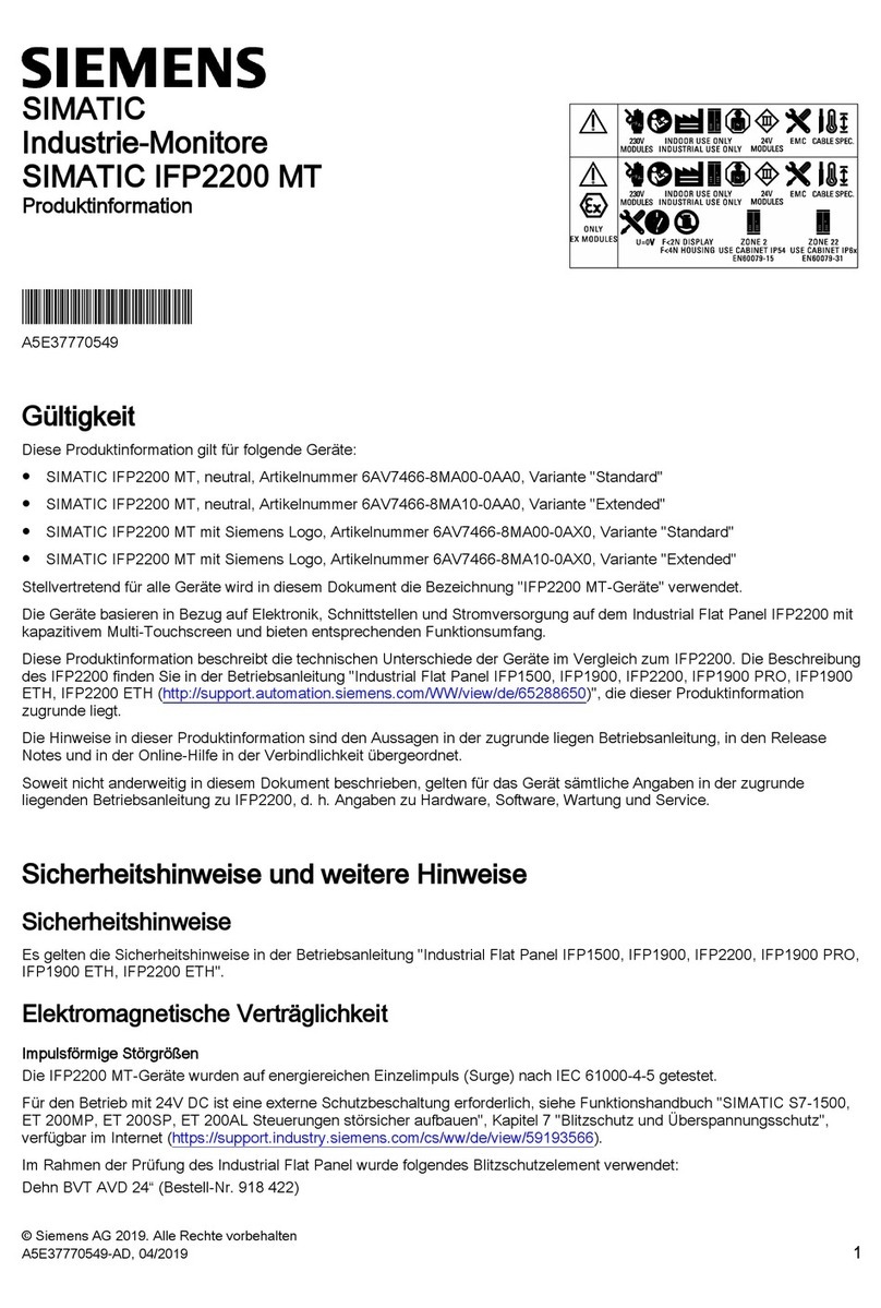
2.1 Product identification
Description Example
Part number PN: R911123456
Type code TYPE: DE00...
Serial number SN: 123456789123456
Plant (7260)
Manufacturing date MD: 17W40
Name of origin Made in...
Company address Bosch Rexroth AG, 97816 Lohr, Germany
CE conformity marking CE
Rexroth barcode
Test marking I-V-C-B-T-V
Voltage specification In 24 V DC
Current specification In 1.5 A
Ambient temperature T(amb) 0-55 °C
Certification markings UL, FCC, China-RoHS, ...
Tab. 2-1: Specifications on the type plate, example
2.2 Scope of delivery
●Multi-touch display
●Safety instructions
●24 V connection terminal
●E-Stop terminal
●Key terminal
3 Using safety instructions
3.1 Structure of the safety instructions
The safety instructions are structured as follows:
ctrlX HMI DE0015, DE0021 Multi-Touch
Displays (Housing Devices)
3/45
Using safety instructions
R911405731_Edition 02 Bosch Rexroth AG

Burns and chemical burns due to wrong
battery treatment!
CAUTION
Safety alert symbol
Signal word
Avoiding danger
Do not open the batteries and do not heat them over 80 °C.
Consequences and
source of danger
Fig. 3-1: Structure of the safety instructions
3.2 Explaining signal words and safety alert symbol
The safety instructions in this documentation contain specific signal words
(danger, warning, caution, notice) and, if necessary, a safety alert symbol
(according to ANSI Z535.6-2006).
The signal word draws attention to the safety instruction and indicates the risk
potential.
The safety alert symbol (triangular safety reflector with exclamation marks),
preceding the signal words Danger, Warning, Caution indicates hazards for
persons.
DANGER
In case of non-compliance with this safety instruction, death or serious injury
will occur.
WARNING
In case of non-compliance with this safety instruction, death or serious injury
can occur.
CAUTION
In case of non-compliance with this safety instruction, minor or moderate injury
can occur.
4/45
Using safety instructions
ctrlX HMI DE0015, DE0021 Multi-Touch
Displays (Housing Devices)
Bosch Rexroth AG R911405731_Edition 02
NOTICE
In case of non-compliance with this safety instruction, material damage can
occur.
3.3 Symbols used
Pointers are displayed as follows:
This is a note.
Tips are displayed as follows:
This is a tip.
3.4 Explaining the signal alert symbol on the device
krax
If this symbol is on your device, you have to observe the documentation
on the device. The respective documentation informs on the type of
hazard as well as the steps required to avoid this hazard.
4 Intended use
The Bosch Rexroth operator displays are passive operator and visualization ter-
minals. They form a PC-based operator terminal when used with a Bosch
Rexroth control cabinet PC.
Risk of damaging the device if not expressly sta-
ted accessories, mounting parts and other com-
ponents, cables, lines, software and firmware
are used.
NOTICE
The operator displays may only be used as intended and with the accessories,
mounting parts and other components specified in this documentation. Compo-
nents that are not expressly mentioned must neither be attached nor connected.
The same applies to cables and lines.
Only to be operated with the component configurations and combinations ex-
pressly defined and with the software and firmware specified in the correspond-
ing functional description.
Typical areas of application of the operator display:
ctrlX HMI DE0015, DE0021 Multi-Touch
Displays (Housing Devices)
5/45
Intended use
R911405731_Edition 02 Bosch Rexroth AG

●Handling and assembly systems
●Packaging and food processing machines
●Printing and paper converting machines
●Machine tools
●Wood processing machines
The operator displays may only be operated under the mounting and installation
conditions, the position and the ambient conditions (temperature, degree of
protection, humidity, EMC etc.) specified in this documentation.
Danger of destruction of the touch screen if op-
erated with inappropriate objects.
NOTICE
Operate the touch screen only with your finger or with a touch pen suitable for
capacitive touch screens.
4.1 Intended use of E-STOP control units
E-STOP control units are electromechanical switching devices to protect per-
sons. E-STOP control units are used for a fast switch-off, to reach a safe state
for machines, vehicles and systems and to avoid or reduce hazards and damages
to people and machines.
The following regulations apply in particular to commissioning, use and technical
inspections:
●Machinery directive 2006/42/EC
●Safety regulations
●Accident prevention regulations/safety rules
Manufacturers and operators of machines with an E-STOP control unit are re-
sponsible to comply with the operating manual and the current safety guidelines
and rules.
To install and operate E-STOP control units, asses the risk for an intended use.
Note the following requirements:
●EN ISO 13849-1:2015
●EN ISO 13849-2:2012
●EN ISO 13850:2015
●EN 60204-1/A1:2009
6/45
Intended use
ctrlX HMI DE0015, DE0021 Multi-Touch
Displays (Housing Devices)
Bosch Rexroth AG R911405731_Edition 02
5 Spare parts, accessories and wear parts
5.1 External 24 V power supply unit
Ordering code Part number Description
VAP01.1H-W23-024-010-NN R911171065 External 24 V power supply unit for
IndraControl V-devices
Tab. 5-1: External 24 V power supply unit for the operator display
5.2 Uninterruptible power supply
Ordering code Part number Description
VAU02.1S-024-024-072-NN R911385289 Uninterruptible Power Supply
24 V DC, 72 watt with RS232 interface
Tab. 5-2: Uninterruptible power supply (UPS)
5.3 Connecting cables for CDI+ interface
Malfunctions caused by using inappropriate CDI cables.
Use only cables listed in the following overview.
Ordering code Part number Description
RKB0008/000,5 (*******-*******-*******) R911171484 Length: 0.5 m
RKB0008/001,0 (*******-*******-*******) R911171485 Length: 1 m
RKB0008/002,5 (*******-*******-*******) R911170151 Length: 2.5 m
RKB0008/005,0 (*******-*******-*******) R911170152 Length: 5 m
RKB0008/007,5 (*******-*******-*******) R911172971 Length: 7.5 m
RKB0008/010,0 (*******-*******-*******) R911170153 Length: 10 m
RKB0008/015,0 (*******-*******-*******) R911171183 Length: 15 m
RKB0008/020,0 (*******-*******-*******) R911171184 Length: 20 m
RKB0008/025,0 (*******-*******-*******) R911170154 Length: 25 m
RKB0008/030,0 (*******-*******-*******) R911171381 Length: 30 m
RKB0008/035,0 (*******-*******-*******) R911171369 Length: 35 m
RKB0008/040,0 (*******-*******-*******) R911171382 Length: 40 m
RKB0008/050,0 (*******-*******-*******) R911171383 Length: 50 m
RKB0008/055,0 (*******-*******-*******) R911173779 Length: 55 m
RKB0008/060,0 (*******-*******-*******) R911173780 Length: 60 m
ctrlX HMI DE0015, DE0021 Multi-Touch
Displays (Housing Devices)
7/45
Spare parts, accessories and wear parts
R911405731_Edition 02 Bosch Rexroth AG

Ordering code Part number Description
RKB0008/065,0 (*******-*******-*******) R911173781 Length: 65 m
RKB0008/070,0 (*******-*******-*******) R911173782 Length: 70 m
Tab. 5-3: Connecting cables to control cabinet PC, panel PC and operator display.
Further cable lengths are available on request.
5.4 USB connecting cables (USB 2.0)
Ordering code Part number Description
RKB0019/000,5 (*******-*******-*******) R911171165 USB connecting cable, length 0.5 m
RKB0019/001,0 (*******-*******-*******) R911171166 USB connecting cable, length 1 m
RKB0019/003,0 (*******-*******-*******) R911171167 USB connecting cable, length 3 m
RKB0019/005,0 (*******-*******-*******) R911171168 USB connecting cable, length 5 m
5.5 Connecting cables of the display port
The listed display port cables are provided with a special shielding. The display
port cables meet the following specifications:
●Conform to the display port 1.2
●Resolutions up to 4096 × 2160
●Supports HDCP 1.3 and DPCP
Ordering code Part number Description
RKB0063/003,0 (*******-*******-*******) R911391713 Connecting cable of the display port,
length 3 m
RKB0063/005,0 (*******-*******-*******) R911391714 Connecting cable of the display port,
length 5 m
5.6 Support arm adapter
Ordering code Part number Description
VAS09.1-001-NNN-NN R911404269 VESA adapter
VAS09.1-002-NNN-NN R911404270 Adapter for tube mounting for the Rittal
program "CP40" or the Bernstein pro-
gram "CS-480" For matching couplings,
refer to tab. 5-4 "Housing couplings for
VAS09.1-002-NNN-NN" on page 9
8/45
Spare parts, accessories and wear parts
ctrlX HMI DE0015, DE0021 Multi-Touch
Displays (Housing Devices)
Bosch Rexroth AG R911405731_Edition 02

5.6.1 Housing coupling
The matching housing couplings for our support arm adapters can-
not be ordered at Bosch Rexroth. Contact the mentioned manufac-
turers.
Ordering code Vendor Description
CP6664.000 Rittal Housing coupling, rotatable, inclinable stainless steel
Square-shaped mounting surface, 35 mm × 35 mm
CP6664.500 Rittal Housing fastening, rigid, stainless steel
Square-shaped mounting surface, 35 mm × 35 mm
CP6501.050 Rittal Housing coupling, rotatable, inclinable stainless steel, graph-
ite grey
Square-shaped mounting surface, 46 mm × 46 mm
1014800001 Bernstein Coupling CS-480 B.Flex
Square-shaped mounting surface, 46 mm × 46 mm
Tab. 5-4: Housing couplings for VAS09.1-002-NNN-NN
5.7 Wear parts
Wear parts are not subject to any warranty.
Backlight
The service life of the backlight is limited. After this period, the backlight will
produce only 50 % of its original brightness. The service life is 50,000 hours if
the ambient temperature is 25 °C.
6 Ambient conditions
Humidity 85% at 40°C (non-condensing)
Operating temperature 0 to 55°C (with airflow 0.3 m/s)
Storage temperature -20 to 60 °C
Shock protection DIN EN 60068-2-27
Overvoltage category 2
Contamination level 2, no condensation allowed
Mechanical strength IEC 60068-2-64
Acceleration: 2G
Tab. 6-1: Ambient conditions
ctrlX HMI DE0015, DE0021 Multi-Touch
Displays (Housing Devices)
9/45
Ambient conditions
R911405731_Edition 02 Bosch Rexroth AG

Failure of the product due to contaminated air
NOTICE
●The ambient air must not contain acids, alkaline solutions, corrosive agents,
salts, metal vapors and other electrically conductive contaminants in high
concentrations
Defective product due to gases jeopardizing
functions
NOTICE
Due to the risk of corrosion, avoid sulphurous gases (e.g. sulphur dioxide (SO2)
and hydrogen suphide (H2S)). The product is not resistant against these gases.
Risk to damage the device due to external influ-
ences
NOTICE
Keep the device away from oils and emulsions.
7 Technical data
DE0015 DE0021
Display 396 mm TFT (15")
1366 × 768 pixels
16.7 million colors
546 mm TFT (21")
1920 × 1080 pixels
16.7 million colors
Weight 6.8 kg (without support arm adapter)
8.2 kg (with VAS09.1-002)
8.5 kg (with VAS09.1-001)
9.6 kg (without support arm adapter)
11 kg (with VAS09.1-002)
11.3 kg (with VAS09.1-001)
Power consump-
tion
20.6 W max. 32 W max.
Input voltage 24 V DC +25 %, -20 % 24 V DC +25 %, -20 %
Operation Projected capacitive 10-point multi-
touch
Projected capacitive 10-point multi-
touch
Surface of the front
panel
Chemically strengthened front glass Chemically strengthened front glass
Graphic interfaces ●CDI+
●Display port
●HDMI
●CDI+
●Display port
●HDMI
10/45
Technical data
ctrlX HMI DE0015, DE0021 Multi-Touch
Displays (Housing Devices)
Bosch Rexroth AG R911405731_Edition 02
DE0015 DE0021
Degree of protec-
tion
Front panel IP 65 Front panel IP 65
USB 1 × USB 2.0 (type B) at the plugboard
2 × USB 2.0 (type A) at the plugboard
1 × USB 2.0 (type A) on the front
Per USB port max. 500 mA
1 × USB 2.0 (type B) at the plugboard
2 × USB 2.0 (type A) at the plugboard
1 × USB 2.0 (type A) on the front
Per USB port max. 500 mA
Tab. 7-1: Technical data of the display
7.1 E-STOP button
Mechanics Electrics
B10: 65000
B10d = 130000
Exclusion of failure at <6,050 switching cycles
B10: 18922161
B10d = 37844322
Exclusion of failure at <6,050 switching cycles
Tab. 7-2: Service life value of the E-STOP button
7.2 Optical characteristic values
7.2.1 TFT
The maximum permissible number and type of pixel errors of TFT displays de-
pends on the manufacturer and is defined by the respective incoming inspection
of the vendor.
7.2.2 Input system or multi-touch front
The maximum permissible number, type and size of defects on the front, on the
glass or between the display and the front – such as trapped dust, dirt and
scratches is defined in the FT quality guideline.
8 Standards
The products have been developed according to the German editions of the
standards published at the time of product engineering.
8.1 Standards used
Standard Meaning
The E-STOP button is identified as safety component according to machinery directive 2006/42/EC
(annex V-10, E-STOP devices) by the vendor. The compliance with the directive is proven by adher-
ence to the following European standards:
IEC 60947-1 Low-voltage switchgear and controlgear – Part 1: General rules
ctrlX HMI DE0015, DE0021 Multi-Touch
Displays (Housing Devices)
11/45
Standards
R911405731_Edition 02 Bosch Rexroth AG

Standard Meaning
IEC 60947-5-1 Low-voltage switchgear and controlgear – Part 5-1: Control circuit
devices and switching elements – Electromechanical control cir-
cuit devices
IEC 60947-5-5 Low-voltage switchgear and controlgear - Part 5-5: Control circuit
devices and switching elements - Electrical emergency stop de-
vice with mechanical latching function
ISO13849-1 Safety of machinery – Safety-related parts of control systems –
Part 1: General principles for design
IEC 13850 Safety of machinery — Emergency stop function — Principles for
design
Tab. 8-1: Standards used: E-STOP button
8.2 CE marking
8.2.1 Declaration of conformity
The electronic products described in these instructions comply with the require-
ments and the target of the following EU directive and the following harmonized
European standards:
EMC directive 2014/30/EC
The electronic products described in the present instructions are intended for
use in industrial environments and comply with the following requirements:
Standard Title
DIN EN 61000-6-2 Electromagnetic compatibility (EMC)
Part 6-2: Generic standards – Noise immunity for industrial environments (IEC
61000-6-2:2019)
DIN EN 61000-6-4 Electromagnetic compatibility (EMC)
Part 6-4: Generic standards – Emission standard for industrial environments (IEC
61000-6-4:2007+A1:2011)
Tab. 8-2: Standards for electromagnetic compatibility (EMC)
Loss of CE conformity due to modifications at the device
CE marking applies only to the device upon delivery. After modifying
the device, verify the CE conformity.
8.3 FCC
This device was tested and complies with the limit values for a digital device of
class A as per part 15 of the FCC rules. These limit values should ensure an ap-
propriate protection against harmful interferences if the device is operated in an
industrial area. This device creates and uses high-frequency, it can radiate it and
it can cause harmful interferences of the wireless communication if it is not in-
12/45
Standards
ctrlX HMI DE0015, DE0021 Multi-Touch
Displays (Housing Devices)
Bosch Rexroth AG R911405731_Edition 02
stalled and used as specified in the operating instructions. Harmful interferen-
ces can result if this device is operated on a residential area. In this case, the
user has to eliminate the interferences at his own expense.
This device complies with part 15 of the FCC rules. Operation is subject to the
following two conditions:
●This device may not cause harmful interferences.
●This device has to tolerate any receiving interferences, including interferences
that can cause undesired operation.
8.4 UL/CSA certified
The devices are certified according to
●UL 62368 (Industrial Control Equipment) and
●CSA22.2 No. 61010-2-201 (CSA)
However, there can be combinations or extension stages with a limited or miss-
ing certification. Thus, verify the registration according to the UL marking on the
device.
Loss of UL/CSA conformity due to modifications at the device
UL and CSA marking applies only to the device upon delivery. After
modifying the device, verify the UL and the CSA conformity.
9 Interfaces
Fig. 9-1: Interfaces
9.1 Overview
The following connections are available:
Labeling at the housing Connection type Connection type (at the
device)
Mating connector or ca-
ble (from outside)
XCDI+rx RJ-45 interface (video
and data interface)
RJ45 socket RJ45 plug
XDP Video connection to the
control cabinet PC
Display port socket,
20 pin
Display port plug,
20 pin
XHDMI Video connection to the
control cabinet PC
HDMI female connector,
type A,
19 pin
HDMI connector, type A,
19 pin
ctrlX HMI DE0015, DE0021 Multi-Touch
Displays (Housing Devices)
13/45
Interfaces
R911405731_Edition 02 Bosch Rexroth AG

Labeling at the housing Connection type Connection type (at the
device)
Mating connector or ca-
ble (from outside)
XUSB USB2.0 interfaces USB socket,
4-pin, type A
USB plug,
4-pin, type A
XUSBIN USB2.0 interface to the
control cabinet PC
USB socket,
4-pin, type B
USB plug,
4-pin, type B
X1S1 24 V DC voltage supply Male connector strip, 3-
pin
Female connector strip,
3-pin
Tab. 9-1: Interfaces
Malfunctions due to insufficient shielding!
NOTICE
Use only shielded cables and metallic or conductive connector/coupling covers
with large-area shield support.
9.2 PC voltage supply X1S1
The 24 V DC voltage supply for the display is connected via the "X1S1" connec-
tion.
123
Fig. 9-2: Interface for 24 V voltage supply
Pin Function
①+24 V supply voltage
②0 V supply voltage
③Functional earth
Tab. 9-2:
9.3 USB interfaces XUSB
The devices are provided with two USB interfaces (USB 2.0) on the connector
panel.
14/45
Interfaces
ctrlX HMI DE0015, DE0021 Multi-Touch
Displays (Housing Devices)
Bosch Rexroth AG R911405731_Edition 02
Other manuals for Rexroth ctrlX HMI DE0015
1
This manual suits for next models
1
Table of contents
Other Bosch Industrial Monitor manuals