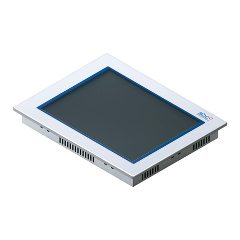
IEI Technology LCD-KIT150G User manual

LCD-KIT
Page i
IEITechnology Corp.
User Manual
MODEL:
LCD-KIT Series
15" ~ 17" Open Frame LCDMonitor
VGA, DVI-D, RoHS
Rev. 3.00 – 25 June, 2013

LCD-KIT
Page ii
Revision
Date Version Changes
25 June, 2013 3.00 Initial release

LCD-KIT
Page iii
Copyright
COPYRIGHT NOTICE
The information in this document is subject to change without prior notice in order to
improve reliability, design and function and does not represent a commitment on the part
of the manufacturer.
In no event will the manufacturer be liable for direct, indirect, special, incidental, or
consequential damages arising out of the use or inability to use the product or
documentation, even if advised of the possibility of such damages.
This document contains proprietary information protected by copyright. All rights are
reserved. No part of this manual may be reproduced by any mechanical, electronic, or
other means in any form without prior written permission of the manufacturer.
TRADEMARKS
All registered trademarks and product names mentioned herein are used for identification
purposes only and may be trademarks and/or registered trademarks of their respective
owners.

LCD-KIT
Page iv
Table ofContents
1 INTRODUCTION.......................................................................................................... 1
1.1 LCD-KIT SERIES LCD MONITOR OVERVIEW ............................................................ 2
1.2 FEATURES................................................................................................................... 2
1.3 MODEL VARIATIONS ................................................................................................... 3
1.4APPLICATIONS ............................................................................................................ 3
1.5 EXTERNAL OVERVIEW................................................................................................ 3
1.5.1 Front View.......................................................................................................... 3
1.5.2 Rear View........................................................................................................... 4
1.5.3 Connectors......................................................................................................... 5
1.5.4 AD Board ........................................................................................................... 6
1.6 SERIES SPECIFICATIONS.............................................................................................. 7
1.7 CERTIFICATIONS ......................................................................................................... 7
2 MECHANICAL OVERVIEW...................................................................................... 8
2.1 INTRODUCTION........................................................................................................... 9
2.2 REAR PANEL............................................................................................................... 9
2.3 CONNECTOR PANEL.................................................................................................... 9
2.3.1 Available Connectors......................................................................................... 9
2.4 PHYSICAL DIMENSIONS ............................................................................................ 10
2.4.1 General Physical Dimensions.......................................................................... 10
2.4.2 LCD-KIT150G Physical Dimensions................................................................11
2.4.3 LCD-KIT170G Physical Dimensions............................................................... 12
2.5 MOUNTING OPTIONS ................................................................................................ 13
3 LCD SPECIFICATIONS ............................................................................................ 14
3.1 LCD SPECIFICATIONS............................................................................................... 15
3.1.1 LCD Overview ................................................................................................. 15
3.1.2 LCD-KIT150G LCD Specifications................................................................. 15
3.1.3 LCD-KIT170G LCD Specifications................................................................. 16
3.2 POWER ADAPTERS.................................................................................................... 16
4AD BOARD................................................................................................................... 18

LCD-KIT
Page v
4.1AD BOARD OVERVIEW............................................................................................. 19
4.2AV-6600AD BOARD OVERVIEW .............................................................................. 19
4.2.1 AV-6600 Peripheral Interface Connectors....................................................... 20
4.2.2 AV-6600 Rear Panel Connectors ..................................................................... 20
5 INSTALLATION ......................................................................................................... 21
5.1 INSTALLATION PRECAUTIONS................................................................................... 22
5.2 UNPACKING.............................................................................................................. 23
5.2.1 Packaging ........................................................................................................ 23
5.2.2 Unpacking Procedure ...................................................................................... 23
5.2.3 Packing List ..................................................................................................... 24
5.3 PRE-INSTALLATION PREPARATION ............................................................................ 24
5.3.1 Tools................................................................................................................. 24
5.4 CONNECTORS ........................................................................................................... 25
5.4.1 VGA Connector................................................................................................ 25
5.4.2 DVI-D Connector............................................................................................. 25
5.4.3 12V Power Connector...................................................................................... 26
5.4.4 Optional Terminal Block.................................................................................. 26
5.5 MOUNTING THE LCD-KIT SERIES LCD MONITOR .................................................. 27
6 OSD CONTROLS........................................................................................................ 28
6.1 USER MODE OSD STRUCTURE................................................................................. 29
6.1.1 OSD Buttons..................................................................................................... 29
6.1.2 OSD Menu Structure........................................................................................ 29
6.2 USING THE OSD....................................................................................................... 30
6.2.1 Main Display Features..................................................................................... 30
6.2.2 Color................................................................................................................ 31
6.2.3 OSD Configurations......................................................................................... 33
7 SOFTWARE DRIVER ................................................................................................ 34
7.1 INTRODUCTION......................................................................................................... 35
7.2 RS-232 OR USB TOUCH SCREEN ............................................................................. 35
7.3 TOUCH PANEL DRIVER INSTALLATION...................................................................... 36
7.4 CHANGE THE TOUCH SCREEN INTERFACE ................................................................ 39
7.5 CALIBRATING THE TOUCH SCREEN........................................................................... 39
LCD-KIT
Page vi
ACERTIFICATIONS .................................................................................................... 42
A.1 ROHS COMPLIANT.................................................................................................. 43
B SAFETY PRECAUTIONS......................................................................................... 44
B.1 SAFETY PRECAUTIONS............................................................................................. 45
B.1.1 General Safety Precautions............................................................................. 45
B.1.2 Anti-static Precautions .................................................................................... 46
B.2 MAINTENANCE AND CLEANING PRECAUTIONS ........................................................ 46
B.2.1 Maintenance and Cleaning.............................................................................. 46
B.2.2 Cleaning Tools................................................................................................. 47
C SMARTOSD................................................................................................................ 48
C.1 IEI SMARTOSD QUICK INSTALLATION GUIDE ......................................................... 49
C.2 PRE-INSTALLATION NOTICE ..................................................................................... 49
C.3 SMARTOSD INSTALL ............................................................................................... 50
C.4 SOFTWARE ILLUSTRATION ....................................................................................... 54
C.4.1 Manage Page................................................................................................... 56
C.4.2 EDID Page...................................................................................................... 57
C.4.3 Image Page...................................................................................................... 58
C.4.4 Display Page (for analog signal).................................................................... 59
C.4.5 Color Page ...................................................................................................... 60
C.4.6 PIP Page.......................................................................................................... 61
C.4.7 System Page..................................................................................................... 62
C.4.8 About Page...................................................................................................... 64
C.5 SMARTOSD FAQ ..................................................................................................... 65
C.5.1 Windows 2000 Installation Failure................................................................. 65
C.5.2 Vista Installation Failure................................................................................. 66
C.5.3 Model Failure.................................................................................................. 67
C.5.4 DCC Port Failure............................................................................................ 67

LCD-KIT
Page vii
List of Figures
Figure 1 1: LCD-KIT Series ............................................................................................................2
Figure 1-2: Typical LCD-KIT Front View.......................................................................................4
Figure 1-3: Typical LCD-KIT Rear View........................................................................................5
Figure 1-4: Typical LCD-KIT Connectors .....................................................................................5
Figure 1-5: AV-6600 AD Board ......................................................................................................6
Figure 2-1: Rear Panel....................................................................................................................9
Figure 2-2: LCD-KIT150G Physical Dimensions (millimeters) .................................................11
Figure 2-3: LCD-KIT170G Physical Dimensions (millimeters) .................................................12
Figure 4-1: AV-6600 AD Board Overview ...................................................................................19
Figure 5-1: VGA Connector .........................................................................................................25
Figure 5-2: DVI-D Connector .......................................................................................................26
Figure 5-3: 12V Power Connector...............................................................................................26
Figure 5-4: Terminal Block ..........................................................................................................27
Figure 6-1: OSD Control Buttons................................................................................................29
Figure 6-2: Main Display Features ..............................................................................................31
Figure 6-3: Color Options ............................................................................................................32
Figure 6-4: OSD Configurations Menu .......................................................................................33
Figure 7-1: Setup Icon..................................................................................................................36
Figure 7-2: Welcome Screen .......................................................................................................37
Figure 7-3: License Agreement...................................................................................................37
Figure 7-4: Initiate Install .............................................................................................................38
Figure 7-5: Installation Starts......................................................................................................38
Figure 7-6: Finish Installation......................................................................................................39
Figure 7-7: PenMount Monitor Icon ............................................................................................40
Figure 7-8: PenMount Monitor Popup Menu..............................................................................40
Figure 7-9: Configuration Screen................................................................................................40
Figure 7-10: Calibration Initiation Screen ..................................................................................41
Figure 7-11: Calibration Screen ..................................................................................................41
Figure C-1: smartOSD Installer ...................................................................................................50
Figure C-2: smartOSD Welcome Screen....................................................................................51

LCD-KIT
Page viii
Figure C-3: smartOSD Folder Select Screen .............................................................................51
Figure C-4: smartOSD Confirm Installation...............................................................................52
Figure C-5: smartOSD Installation Progress .............................................................................52
Figure C-6: smartOSD Installation Complete ............................................................................53
Figure C-7: smartOSD Desktop Icon ..........................................................................................53
Figure C-8: Manage Page.............................................................................................................56
Figure C-9: EDID Page..................................................................................................................57
Figure C-10: Image Page..............................................................................................................58
Figure C-11: Display Page ...........................................................................................................59
Figure C-12: Color Page...............................................................................................................60
Figure C-13: PIP Page ..................................................................................................................61
Figure C-14: System Page ...........................................................................................................62
Figure C-15: About Page..............................................................................................................64
Figure C-16: DLL Missing ............................................................................................................65
Figure C-17: Windows Vista Error ..............................................................................................66
Figure C-18: Install as Administrator..........................................................................................66
Figure C-19: Firmware Incompatibility.......................................................................................67
Figure C-20: DCC Port Failure.....................................................................................................67

LCD-KIT
Page ix
List of Tables
Table 1-1: LCD-KIT Series Model Variations................................................................................3
Table 2-1: General Physical Dimensions ...................................................................................10
Table 2-2: Mounting Holes...........................................................................................................13
Table 3-1: LCD-KIT150G LCD Specifications.............................................................................16
Table 3-2: LCD-KIT170G LCD Specifications.............................................................................16
Table 3-3: Power Adapter Specifications...................................................................................17
Table 4-1: AV-6600 Peripheral Interface Connectors................................................................20
Table 4-2: AV-6600 Rear Panel Connectors...............................................................................20
Table 5-1: Rear Panel Connectors ..............................................................................................25
Table 5-2: VGA Connector Pinouts.............................................................................................25
Table 5-3: DVI-D Connector Pinouts...........................................................................................26
Table 6-1: OSD Menus..................................................................................................................30
Table C-1: SmartOSD Menu Structure........................................................................................55

LCD-KIT
Page 1
Chapter
1
1Introduction

LCD-KIT
Page 2
1.1 LCD-KIT Series LCD Monitor Overview
Figure 1 1: LCD-KIT Series
The LCD-KIT series LCD monitor is the latest member of IEI’s line of sophisticated LCD
designs, and it has been improved to be RoHS compliant. It is designed to fit industrial
automation, or any other applications that require minimum installation space and
flexible configuration. Flexible analog or digital interfaces are provided for ease of
connection with a management computer. If remote/non-attentive control is preferred,
RS-232 or USB interfaces can be used with customized adapter cables.
1.2 Features
The LCD-KIT series have the following standard features:
Analog VGA interface supports most general system boards
350 nits (LCD-KIT170) / 400 nits (LCD-KIT150) high brightness
Over 50,000 hrs MTBF long lifetime panel
Advanced thermal and air-flow design
Supports panel mounting
12 V DC power input via adapter
M models have 9~36 V DC power connector
Long product life support
RoHS compliant

LCD-KIT
Page 3
1.3 ModelVariations
The LCD-KIT series offers the following model variations.
Model Number LCD 9~36V Power
Input
LCD-KIT150G-R30 15” -
LCD-KIT150GM-R30 Yes
LCD-KIT170G-R30 17” -
LCD-KIT170GM-R30 Yes
Table 1-1: LCD-KIT Series Model Variations
1.4 Applications
IEI’s series of LCD monitors are designed for system manufacturers, integrators, or
value-added resellers that want to provide all the performance, quality and reliability of an
LCD display solution at a cost effective price. IEI’s LCD kits offer additional components
such as cables, an inverter and power supply with controller interfaces that include VGA
and DVI.
1.5 External Overview
The following sections describe the physical layout of the LCD-KIT series LCD monitors.
1.5.1 Front View
The front of the LCD-KIT series LCD monitor is a flat panel TFT LCD screen attached to a
metal chassis. Figure 1-2 shows a typical LCD-KIT front view.

LCD-KIT
Page 4
Figure 1-2: Typical LCD-KIT Front View
1.5.2 Rear View
The rear of the LCD-KIT series LCD monitor is a metal chassis. An on screen display
(OSD) control button panel, if present, is located vertically on the left side of the chassis
with the following control buttons:
LCD On/Off
Auto
Left
Right
Menu
The OSD panel also has one power LED.
Figure 1-3 shows a typical LCD-KIT rear panel.

LCD-KIT
Page 5
Figure 1-3: Typical LCD-KIT Rear View
1.5.3 Connectors
Each LCD-KIT series LCD monitor has a number of interface connectors on either the top
or right panel of the chassis (when viewing the rear panel). Figure 1-4 shows a typical
LCD-KIT connector panel. Each model may include or exclude additional connectors.
Refer to Section 2.3 for listings of LCD-KITs and their connectors. All connectors are fully
described in Section 5.4.
Figure 1-4: Typical LCD-KIT Connectors

LCD-KIT
Page 6
1.5.4 AD Board
The LCD-KIT series LCD monitor AD boards provide a wide variety of control interfaces,
receiving and managing signals from a CPU card through cabling. Figure 1-5 shows the
AV-6600 AD board as a sample of a typical AD board for the LCD-KIT series LCD monitor.
Refer to Chapter 4for a complete description of AD boards and their connectors.
Figure 1-5: AV-6600 AD Board

LCD-KIT
Page 7
1.6 Series Specifications
The table below shows the LCD-KIT Series specifications.
LCD-KIT LCD-KIT150G LCD-KIT150GM LCD-KIT170G LCD-KIT170GM
LCD Type 15" TFT 15" TFT 17" TFT 17" TFT
Resolution 1024 x 768 1024 x 768 1024 x 768 1024 x 768
Brightness (cd/m2) 400 400 350 350
Contrast Ratio 700:1 700:1 800:1 800:1
Display Color 16.2M 16.2M 16.7M 16.7M
Pixel Pitch (mm) 0.297 0.297 0.264 0.264
Viewing Angle (H/V) 160/140 160/140 170/160 170/160
AD Board AV-6600 AV-6600 AV-6600 AV-6600
Input Interface Analog VGA
+ DVI-D
Analog VGA
+ DVI-D
Analog VGA
+ DVI-D
Analog VGA
+ DVI-D
OSD function Yes Yes Yes Yes
Smart-OSD Yes Yes Yes Yes
Dimensions (WxHxD)
(mm)
364.1 x 262.1 x
41.3 364.1 x 262.1 x 41.3 390.4 x 299.6 x 46.3 390.4 x 299.6 x 46.3
Operating
Temperature -10°C~50°C -10°C~50°C -10°C~50°C -10°C~50°C
Storage
Temperature -20°C~60°C -20°C~60°C -20°C~60°C -20°C~60°C
Net Weight 3.8 kg 3.8 kg 6 kg 6 kg
Input Voltage 12VDC 9~36VDC 12VDC 9~36VDC
Power Adapter 60W N/A 60W N/A
Certificates CE CE Internal Prescan
EMC Class A
Internal Prescan
EMC Class A
1.7 Certifications
All LCD-KIT series LCD monitor models comply with the following international standards:
RoHS
For a more detailed description of these standards, please refer to Appendix A.

LCD-KIT
Page 8
Chapter
2
2MechanicalOverview

LCD-KIT
Page 9
2.1 Introduction
This chapter describes the general mechanical overview of the LCD-KIT series LCD
monitors including rear panel variations, available interfaces and overall dimensions.
2.2 Rear Panel
The following models of the LCD-KIT series LCD monitor have an OSD control panel
located vertically along the left side of the rear panel:
LCD-KIT150G
LCD-KIT170G
Figure 2-1 shows the location of the rear panel OSD controls.
Figure 2-1: Rear Panel
2.3 Connector Panel
All external peripheral interface connectors are located on the rear panel of the LCD-KIT
series LCD monitor. The following sections describe the rear panel variants and their
associated connectors.
2.3.1 Available Connectors
There are a number of rear panel peripheral device connectors available for the LCD-KIT
series LCD monitor.

LCD-KIT
Page 10
VGA connector
DVI-D connector
12 V DC power connector
9~36 V DC power connector (M model only)
2.4 Physical Dimensions
The following sections describe the physical dimensions for each model of the LCD-KIT
series LCD monitor.
2.4.1 General Physical Dimens ions
General physical dimensions for the LCD-KIT series LCD monitors are shown in Table
2-1.
Model Width (mm) Height (mm) Depth (mm)
LCD-KIT150G 364.1 262.5 41.9
LCD-KIT170G 390.4 300 46.9
Table 2-1: General Physical Dimensions

LCD-KIT
Page 11
2.4.2 LCD-KIT150G Physical Dimens ions
The physical dimensions of the LCD-KIT150G are shown in Figure 2-2.
Figure 2-2: LCD-KIT150G Physical Dimensions (millimeters)
This manual suits for next models
1
Table of contents
Other IEI Technology Industrial Monitor manuals