1.2 How to service, English
How to service, English 1.3
How to service
Servicing
The PDP may only be serviced by qualied technical personal.
If it is not possible to determine the location of the fault or replacing spare part
does not clear the fault, please contact your national Service Center for technical
support.
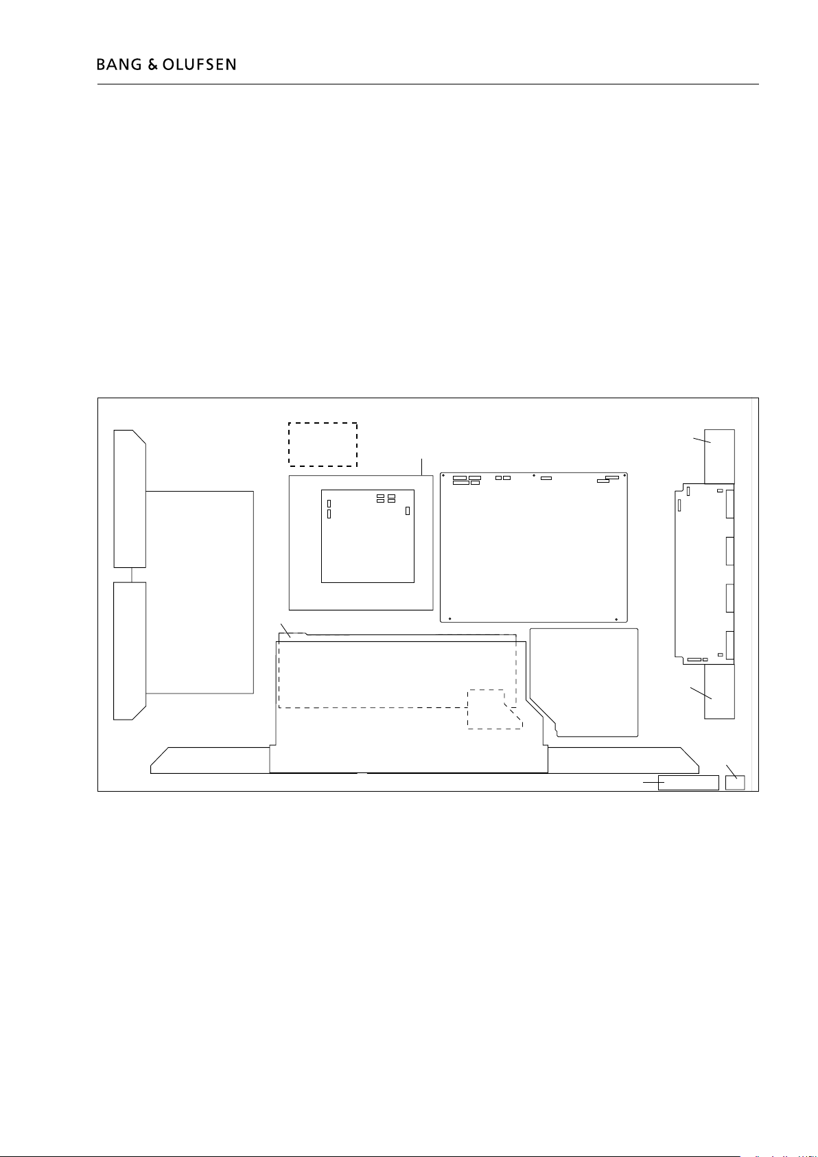
Handling
The PDP must always be placed vertical to avoid damaging it self.
There is a major risk on damaging the PDP if it is placed in a horizontal position.
Whenever possible place the PDP in the servicestand.
Clean the product
Never use alcohol or other solvents to clean any part of the product!
Use white gloves to avoid smudging the contrast screen.
Wipe dust off the surfaces using a dry, soft cloth or a micro bre cloth. Remove
grease stains or persistent dirt with a soft, lint-free, rmly wrung cloth, dipped in a
solution of water containing only a few drops of mild detergent, such as washing-up
liquid.
To retain the optimum performance of the screen, make sure that no streaks or
traces of the cleaning uid are left on the screen.
Burn-in
Burn-in on the PDP might occur when displaying a non-moving picture for more
than app. 30 minutes.
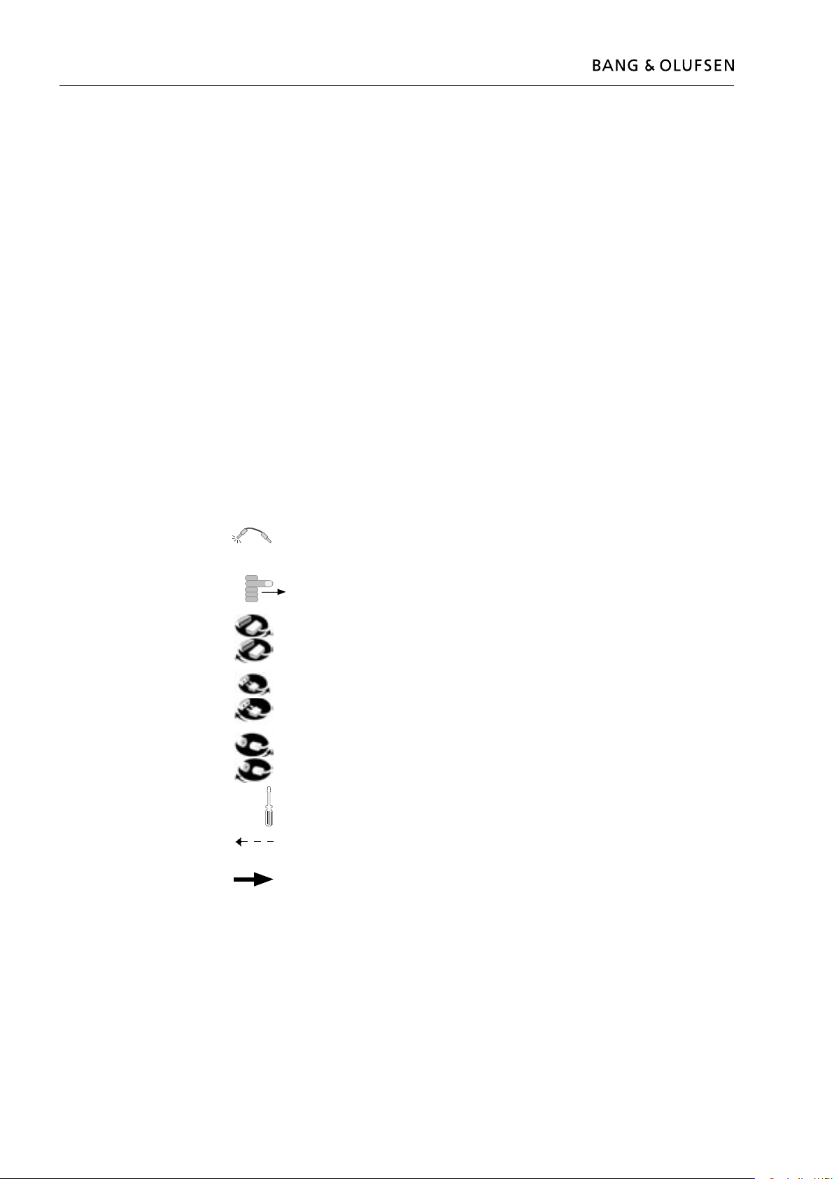
Warning
Static electricity
Static electricity may damage the product.
Static-protective eld service kit.
A static-protective eld service kit must always be used when the product is
disassembled or modules are being handled.
Follow the instructions in the guide and use the ESD-mat for both old and new
modules.
Please note:
When mains voltage on the television is required, remove the connection between
the PDP and the ESD-mat.
The chassis or modules must always be connected to the static-protective eld
service kit or placed in an ESD-proof bag.
Symbol of safety components
When replacing components with this symbol, the same type has to be used, also
the same values for ohm and watt.
The new component is to be mounted in the same way as the replaced one.
STATIC ELECTRICITY
MAY DESTROY THE
PRODUCT