manuals.online logo
Brands
  1. Home
  2. •
  3. Brands
  4. •
  5. Hague Quality Water
  6. •
  7. Water Filtration System
  8. •
  9. Hague Quality Water HW-RO-B Troubleshooting guide

Hague Quality Water HW-RO-B Troubleshooting guide

OWNER'S MANUAL & INSTALLATION GUIDE
Quality Water International
®
Hague Reverse Osmosis
HW-RO-B
Read the entire manual to familiarize yourself with the
system and determine the best location for installation.
Check and comply with all local plumbing codes.
1. 
valve under the sink.
2. Temporarily place system tank into the sink cabinet
(or desired location) to ensure adequate space and
proper positioning.
3. Wait to cut tubing and follow instructions below.



from the manifold to the desired location of the faucet

for both connections. Remove system and tank from
under your sink to begin installation.
Step 1
Step 2
Step 3
Step 4
BOX CONTENTS PLAN FOR INSTALLATION
INSTALLATION OVERVIEW
PREPARE SITE FOR INSTALLATION
• Advanced plumbing
knowledge
• Tape Measure
• Utility Knife
• Screwdriver (Phillips)
• ⅛" & ⁷⁄32" Drill Bits/Drill
• Adjustable Wrench
• Bleach
• Safety Glasses
• Pencil
• Masking Tape
• Pan or Bucket
Step 5
Step 6
Step 7
Step 8
HOT COLD
QualityWater Inter national
®
A
C
K


T
E
U
U

N
V
G
H
PARTS INCLUDED FOR INSTALLATION







Tank Connector

Plumber’s Tape






90° Elbow







AQ
JR
C K 
LT
EMU
N V
GO
X
HP
RECOMMENDED TOOLS FOR INSTALLATION:
Quality Water International
®
A
B
E
F
N
O
T
J
K
M
L
H
SP
R
Q
U V
I
C
XW
1. 
2. Turn on the kitchen faucet to release pressure and allow water to drain from the line.
3. 

an adjustable wrench.
4. 
1. 
mount system manifold. To help gauge the right


aligning top connection points and push up and to the
right until sumps are locked in. Allow at least 4 to 6


1. On the nipple on top of the tank, apply plumber’s
tape 4 or 5 times in the same direction as the threads.
2. Hand tighten the tank connector onto the tank nipple
until secure.
NOTE: Do not cross thread or over tighten.
3. Using mount stand, place tank near the system




C. Place brass insert into the opening of white tube.



the plastic sleeve and create a seal. NOTE: Use a wrench to ensure complete seal.
Avoid over tightening. Do not connect the other end at this time.
1 INSTALL BRASS TEE FITTING
3 INSTALL WATER STORAGE TANK
2 INSTALL SYSTEM MANIFOLD
OptimH2O™
A B C D E F
2. Make sure the manfold is level. Mark wall

bracket on back of manifold.
3. 

NOTE: Use caution not to drill into
anything beyond the cabinet wall.
4. 
5. Remove the sumps from manifold by turning each sump to the left and pulling down before

4. 

Be sure that all electrical
appliances and outlets are turned
o at the circuit breaker before
working in the cabinet area.
Please wear safety glasses to
protect eyes when drilling.
COLDHOT
4 INSTALL FAUCET 5 INSTALL DRAIN CONNECTOR
NOTE: You will need a sink top hole between 1



1. 



2. 
with countertop. Position toggle bolts under sink surface being certain faucet stem will
not be obstructed. Loosely fasten faucet base to countertop by tightening toggle bolts,
alternating between left and right sides to tighten evenly. Leave loose to adjust faucet body
as desired.
3. Route the 3 tubes attached to faucet body through the faucet base and through hole in sink

4. To adjust faucet body handle to desired location, turn ¼ clockwise and hold faucet base

5. 
and pull facuet body and tubing up. Then tighten faucet base by tightening toggle bolts
evenly. Make sure not to over tighten.
6. 
7. Attach faucet spout to faucet body by screwing spout nut to body.
1. 
2. Remove protective cover from back of foam seal.
3. Knock center hole out, align holes, and attach to front plate of drain connector.
4. Allowing room for drilling, position the drain connector on sink drain pipe above drain trap.
5. 
6. Using drain connector port as drill guide, drill 


1 2 3 4
567
1. Brass Tee to Manifold “INLET” (¼” white tubing)
1. Take the white tubing leading from the brass tee (installed in step 1) and insert it into

2. Manifold to Faucet (⅜” white tubing already attached to faucet)


3. Manifold to Tank (⅜” white tubing already attached to tank)
1. Take the white tubing leading from the storage tank
(installed in step 3) and insert it into the manifold port

until it stops.
4. Air Gap to RO Membrane (¼” red tubing from faucet)



5. Faucet to Drain Connector (⅜” red tubing from faucet)

way into the drain connector.
COLDHOT
6 CONNECT TUBING
123
0.95”
TUBING DO’S
ALL THE WAY IN to

nearly a full inch.

insert into all inlets and outlets.

crimping, kinks, loops or folds.
TUBING DONT’S
DO NOT cut tubing too short.
Always double check measurements
before cutting.


TUBING CONNECTIONS:





1
1
4
4
5
5
2
2
3
3
3
2
1
WARNING:
Faucet
will leak if
restrictor is
not installed.
7 FILTER INSTALLATION 8 SANITIZE, PRESSURE TEST, & PURGE SYSTEM


1. 
the system manifold). Make sure all connection points are aligned and push the top of the
sump up and into the system manifold. Turn it towards the right until it locks in.
2. Repeat step 1 for stages 2 and 3 as shown below.
SANITIZE


1. 
2. Turn on RO faucet to empty tank.
3. 

4. Using included eye dropper, add 3ml
of household bleach into open end of
tank white tubing.
Note: Bleach needs to be handled

5. Reconnect the tubing to the tank in


6. 

water. See Purge instructions below.
PRESSURE TEST

1. 
2. To purge air from the plumbing system, turn on kitchen faucet. Close faucet
when water runs smooth.
3. 
4. 

5. 




PURGE
1. 

2. 




stop automatically when tank is at capacity.
11 23
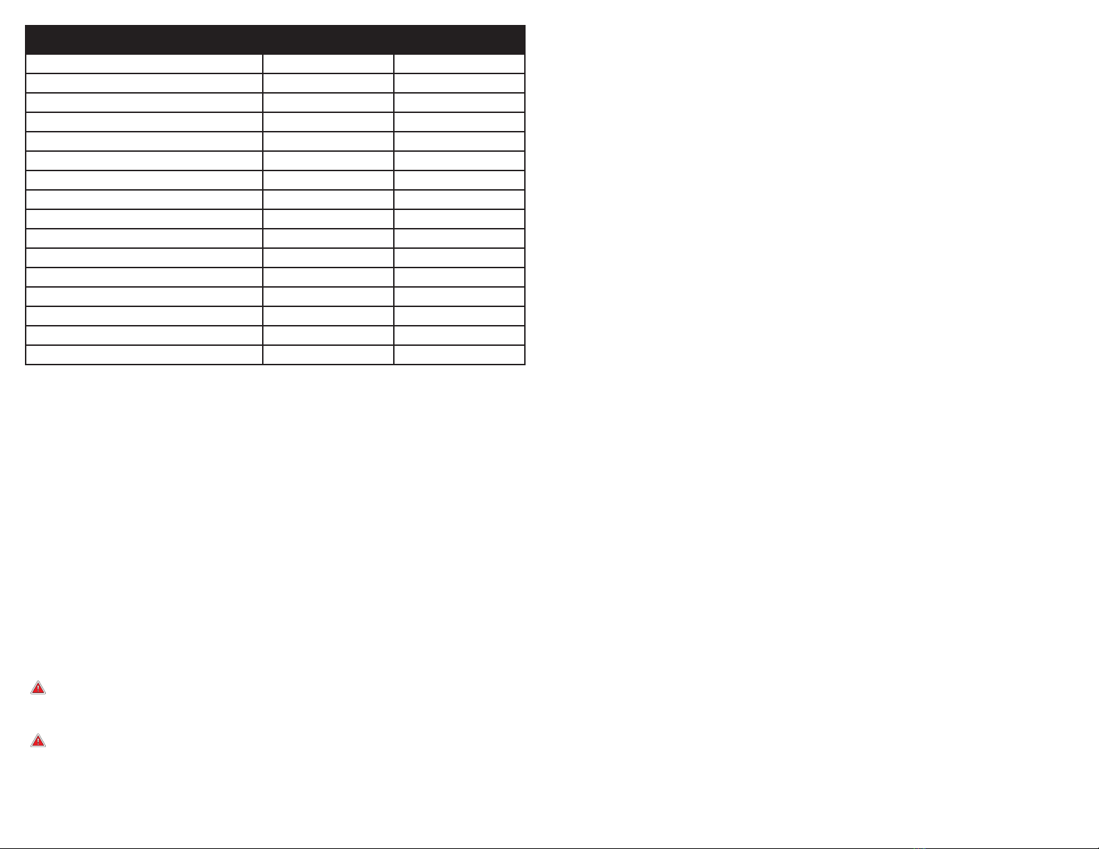
3-STAGE RO SYSTEM – MODEL HAGUE REVERSE OSMOSIS
U.S. Metric
Membrane Production135 gpd 132 lpd
195% minimum 95% minimum
213.32 gpd 50.4 lpd
2 
 1000 ppm 1000 ppm
 10 gpg 2.64 gpL
 3.0 ppm 3.0 ppm
  
  
  
23.2 gallons 12.11 liters
  
  
317.91% 17.91%
Recovery429.43% 29.43%
SPECIFICATIONS – QUALIFIED SYSTEM PERFORMANCE


1. 


Membrane that has been rinsed for 24 hours. The production rate of a new Membrane can
decrease by 10% per year or more, depending upon the scaling and fouling tendencies of the

2. 
3. 

typical daily usage.
4. 
system that is available to the user as reverse osmosis treated water when the system is
operated without a storage tank or when the storage tank is bypassed.





NON-POTABLE WATER SOURCES:




ARSENIC REDUCTION:
Arsenic (abbreviated As) is found naturally in some well water. Arsenic in water has no color,


well, you can have the water tested. The local health department or the state environmental






lab to determine what type and how much of each type of arsenic is in the water. Check with the
labs in your area to see if they can provide this type of service.
Reverse osmosis (RO) water treatment systems do not fully remove trivalent arsenic from water.

rapidly convert trivalent arsenic to pentavalent arsenic. Other water treatment chemicals such
as ozone and potassium permanganate will also change trivalent arsenic to pentavalent arsenic.
A combined chlorine residual (also called chloramine) may not convert all the trivalent arsenic.

combined chlorine is used in the water system.

arsenic to pentavalent arsenic. The system was tested in a lab. Under testing conditions, the


Have the treated water tested for arsenic to check whether the system is working properly.



NITRATE/NITRITE TEST KIT:


test kit. Product water should be monitored periodically according to the instructions provided
with the test kit.
INSTALLATIONS IN THE COMMONWEALTH OF MASSACHUSETTS:


of Massachusetts must be followed in these cases.
CARBON FILTERS - CHANGE EVERY 6 MONTHS*


replace more often with high water usage or high sediment level. Replacing these cartridges in



RO MEMBRANE CARTRIDGE - CHANGE EVERY 12 MONTHS
The RO membrane is located in stage 2. This membrane reduces the dissolved solids and

to replace your RO membrane every 12 months. Membrane life depends on pH and supply





local Hague Dealer.
FLOW RATE AND OUTPUT ARE DETERMINED BY 3 FACTORS:
1. 
2. 
3. 





consider installing a permeate pump or booster pump if your pressure is below 40 psi.
DRAIN FLOW RESTRICTOR
The restrictor is vital for proper operation of the RO membrane cartridge as it keeps water




WHAT IS COVERED:
This warranty covers defects in materials or workmanship in manufacturing of your Hague

FOR HOW LONG:

WHAT IS NOT COVERED:

compliance with the instructions or that have been abused or operated incorrectly. The


purpose or the implied warranty of merchantability. Hague shall not be liable for any incidental,



warranty is voided if the product is used with parts that are not genuine Hague parts.

WHAT HAGUE WILL DO:



HOW TO GET SERVICE:


HOW STATE LAW APPLIES:



rights which vary from state to state.
WARRANTY CARD:



FURTHER EXCLUSIONS AND LIMITATIONS ON WARRANTY:
This warranty is null and void unless the Hague Appliance was purchased from an independent


LIMITED 2 YEAR WARRANTY
Quality Water International
®


Other Hague Quality Water Water Filtration System manuals

Hague Quality Water WaterMax H5000 Programming manual

Hague Quality Water

Hague Quality Water WaterMax H5000 Programming manual

Hague Quality Water WaterMax H6000 Programming manual

Hague Quality Water

Hague Quality Water WaterMax H6000 Programming manual

Popular Water Filtration System manuals by other brands

Pentair EVERPURE Claris EV4339-91 quick start guide

Pentair

Pentair EVERPURE Claris EV4339-91 quick start guide

Panasonic ET-EMF320C operating instructions

Panasonic

Panasonic ET-EMF320C operating instructions

HATHASPACE HSP001 quick start guide

HATHASPACE

HATHASPACE HSP001 quick start guide

Parker Hiross Hyperfilter NFF380 user manual

Parker Hiross

Parker Hiross Hyperfilter NFF380 user manual

Strix Aqua Optima Liscia Instructions for use

Strix

Strix Aqua Optima Liscia Instructions for use

DH Instruments 1-2 IN. FILTER KIT instruction sheet

DH Instruments

DH Instruments 1-2 IN. FILTER KIT instruction sheet

Watts Premier WP4V-50 Installation, operation and maintenance manual

Watts

Watts Premier WP4V-50 Installation, operation and maintenance manual

AQUAPHOR ONYX operating manual

AQUAPHOR

AQUAPHOR ONYX operating manual

WilTec CPF-50000 instruction manual

WilTec

WilTec CPF-50000 instruction manual

AquaMaster AMS700 Owner's manual and installation guide

AquaMaster

AquaMaster AMS700 Owner's manual and installation guide

Grohe Blue Pure manual

Grohe

Grohe Blue Pure manual

BRÖTJE NEOP 70 installation instructions

BRÖTJE

BRÖTJE NEOP 70 installation instructions

Novy 6830060 installation instructions

Novy

Novy 6830060 installation instructions

VGE Xclear IMMERSION UV-C 40W AMALGAM manual

VGE

VGE Xclear IMMERSION UV-C 40W AMALGAM manual

Envirosource WAW-4012 user manual

Envirosource

Envirosource WAW-4012 user manual

Coway CHP-04AR user manual

Coway

Coway CHP-04AR user manual

Yamato WG 1000 instruction manual

Yamato

Yamato WG 1000 instruction manual

SunSun CPF Series Operation manual

SunSun

SunSun CPF Series Operation manual

manuals.online logo
manuals.online logoBrands
  • About & Mission
  • Contact us
  • Privacy Policy
  • Terms and Conditions

Copyright 2025 Manuals.Online. All Rights Reserved.