HAI 45A00-1 User manual

Document Number: 45I00-1 45A00-1
Installation Instructions
DESCRIPTION
The Model 45A00-1 Supervised Wireless Receiver allows up to 64 unique wireless
security transmitters to report information to an HAI controller. The wireless
transmitters replace wired door and window sensors, as well as wired smoke, motion,
glassbreak detectors, and handheld keyfobs. These transmitters report status
information to the 45A00-1 Receiver which, in turn, processes the information and
reports it to the HAI controller.
COMPATIBLE TRANSMITTERS
The Model 45A00-1 Supervised Wireless Receiver is compatible with HAI Wireless
Transmitters. These transmitters include the 46A00-1 Door/Window Transmitter,
47A00-1 Quad Pet Immune Motion Detector, 48A00-1 4 Button Keyfob, 49A00-1
Smoke and Carbon Monoxide Detector, and 50A00-1 Panic/Alert Pendant.

1
INSTALLATION
Install the receiver in a central area of the premises, as high above ground as practical.
The receiver may be mounted up to 1000 feet from the HAI controller.
¾The receiver should be at least 5 feet from the controller or any other
electronic device.
¾Avoid areas where receiver will be exposed to moisture.
¾Avoid areas with excessive metal or electrical wiring. If unavoidable,
mount where antenna extends above a metallic surface.
When the location of the receiver has been established:
1. Position the supplied Mounting Base so that the Mounting Base Latch
is at the top. Hold the Mounting Base against the mounting surface
(allow at least a 6-inch clearance above the Mounting Base) and secure
it using the supplied screws (see Figure 1).
2. Align the notches on the back of the Wireless Receiver case with the
tabs on the Mounting Base. Make sure the tabs are fully inserted into
the notches and push downward to latch.
MOUNTING
BASE
MOUNTING
BASE LATCH
MOUNTING HOLE
TAB
TAB
MOUNTING HOLE

2
MODE SET
+12V A B GND
D3
TYPE
LED LED
DISPLAY
MODE
LED
MODE/ADVANCE
SWITCH
SET
SWITCH
ANTENNA
SPECIFICATIONS
Dimensions: 2.5W x 3.75H x 1.0D, excluding antenna
Current Consumption: 30mA maximum
Operating Temperature: 32oF - 140oF (0 oC - 60o C)
Maximum Humidity: 90% relative humidity, non-condensing

3
OPERATION
The two operating modes of the receiver are "Run" and "Setup".
In Run Mode, with the receiver connected to and communicating with the controller,
the Mode LED (see Figure 2) should blink once per second. The receiver monitors the
status of each transmitter. If the status condition of a transmitter changes, it is
reported to the receiver and the information is updated on the LED display and the
Status LED will flash.
The transmitter number flashes on the display and the Status LED flashes whenever a
report is received from a transmitter. The display will continually display the status of
any transmitters that are violated (not ready) or that have trouble. The transmitter
number flashes on the display followed by the status condition(s).
LED DISPLAY INFORMATION ABOUT THE LED DISPLAY
1.1 Displays the number of the transmitter with a change in
condition.
A L Displays that the current transmitter is "NOT READY".
C O Displays that the cover was removed from the current
transmitter.
S F Displays that the current transmitter has a supervision failure.
L O Displays that the current transmitter has reported a battery low.
NOTE: If the receiver is not communicating with the controller, the Mode LED will
blink four times per second.
SET - The Set switch (see Figure 2) is used to increment or change the current
selection.
MODE /ADVANCE - The Mode/Advance switch (see Figure 2) is used to enter Setup
Mode, advance to the next Setup item, and to confirm a selection. It is also used to
exit Setup Mode.
LED DISPLAY - The LED Display (see Figure 2) is used to show the status of each
transmitter and to ensure proper setup.
MODE LED - In Run Mode, the Mode LED (see Figure 2) is used to indicate
communication status with the controller. In Setup Mode, the Mode LED is used to
indicate if a transmitter sends a restore code.

4
TYPE LED - In Setup Mode, the Type LED (see Figure 2) is used to indicate if a
transmitter is supervised.
SETUP MODE
The Setup Mode is used to configure the general operating parameters of the receiver,
to program a transmitter into the receiver, and to change the characteristics of a
programmed transmitter. The Mode LED does not blink in Setup Mode.
To enter the Setup Mode:
A. Press and hold the Mode/Advance switch for approximately two seconds.
B. Press the Set switch to increment the value of a Setup item.
C. Press the Mode/Advance switch is to advance to the next Setup item.
Receiver Address
You are first prompted to enter the receiver address. "A" is shown on the left of the
display and the current address is shown on the right. Press the Set switch to
increment the address value. The current address will be stored into memory when the
Mode/Advance switch is pressed. Setup Mode is exited when the Mode/Advance
switch is pressed and held for two seconds.
Number of Addresses
Next, you are prompted to enter the “number of addresses” (see the Setup information
in this document for configuration of each HAI controller). The letter "n" is shown
on the left of the display and the digit for the current number of addresses is shown on
the right of the display. Press the Set switch to increment the number of addresses
value. The current number of addresses will be stored into memory when the
Mode/Advance switch is pressed. Setup Mode is exited when the Mode/Advance
switch is pressed and held for two seconds.
Configuring Transmitters
All of the following locations are used for configuring and programming transmitters.
Each new transmitter can be programmed into the receiver and each programmed
transmitter, along with its characteristics, is displayed and can be modified. The
transmitter number is shown in the LED Display.

5
If no transmitter is programmed in an address location, neither the Mode LED nor the
Type LED will be lit.
If a transmitter is programmed in an address location:
1. The Mode LED indicates whether the transmitter sends restore transmissions
¾The Mode LED is on if the transmitter sends restore transmissions, and off if it
doesn't.
2. The Type LED shows whether the transmitter is supervised.
¾The Type LED is on steady if the transmitter is supervised, and blinks if it isn't.
The Set switch is used to change the characteristics of a programmed transmitter.
Each press of the Set switch cycles through each combination of supervised, sends
restores, or no transmitter programmed.
The Mode/Advance switch is used to advance to the next transmitter address location.
Setup Mode is exited by pressing and holding the Mode/Advance switch for two
seconds.
TEACHING THE RECEIVER A TRANSMITTER ADDRESS
If no transmitter is programmed in an address location, a new transmitter may be
programmed into that address location by activating the desired transmitter. The
activated transmitter will then be entered into that address location. The transmitter
must be activated according to the instructions that accompany the transmitter.
Based on the type of transmitter, the receiver will try to set the supervisory and restore
characteristics that are appropriate for that type of transmitter. These can be changed
as desired using the Set switch.
Once a transmitter is programmed into an address location, the transmitter address will
briefly turn off whenever a transmission from that transmitter is received. This can be
used to verify that the correct transmitter has been programmed and is operating
reliably.
NOTE: The controller ignores the current status of each transmitter while the
receiver is in Setup Mode.

6
TRANSMITTER SETUP
1. Press and hold the Mode/Advance button for two (2) seconds.
2. "A1" will appear. On OmniLT, Omni II, and Lumina "A1" is always
used. On OmniPro II and Lumina Pro the address will depend on the
number of expansion enclosures used (see "OmniPro II / Lumina Pro
Setup" for more information).
3. Press the Mode/Advance button to save any changes and proceed.
4. Next, "n1" will appear. The value of "n" will determine the number of
addresses used.
5. Press the Mode/Advance button to save any changes and proceed.
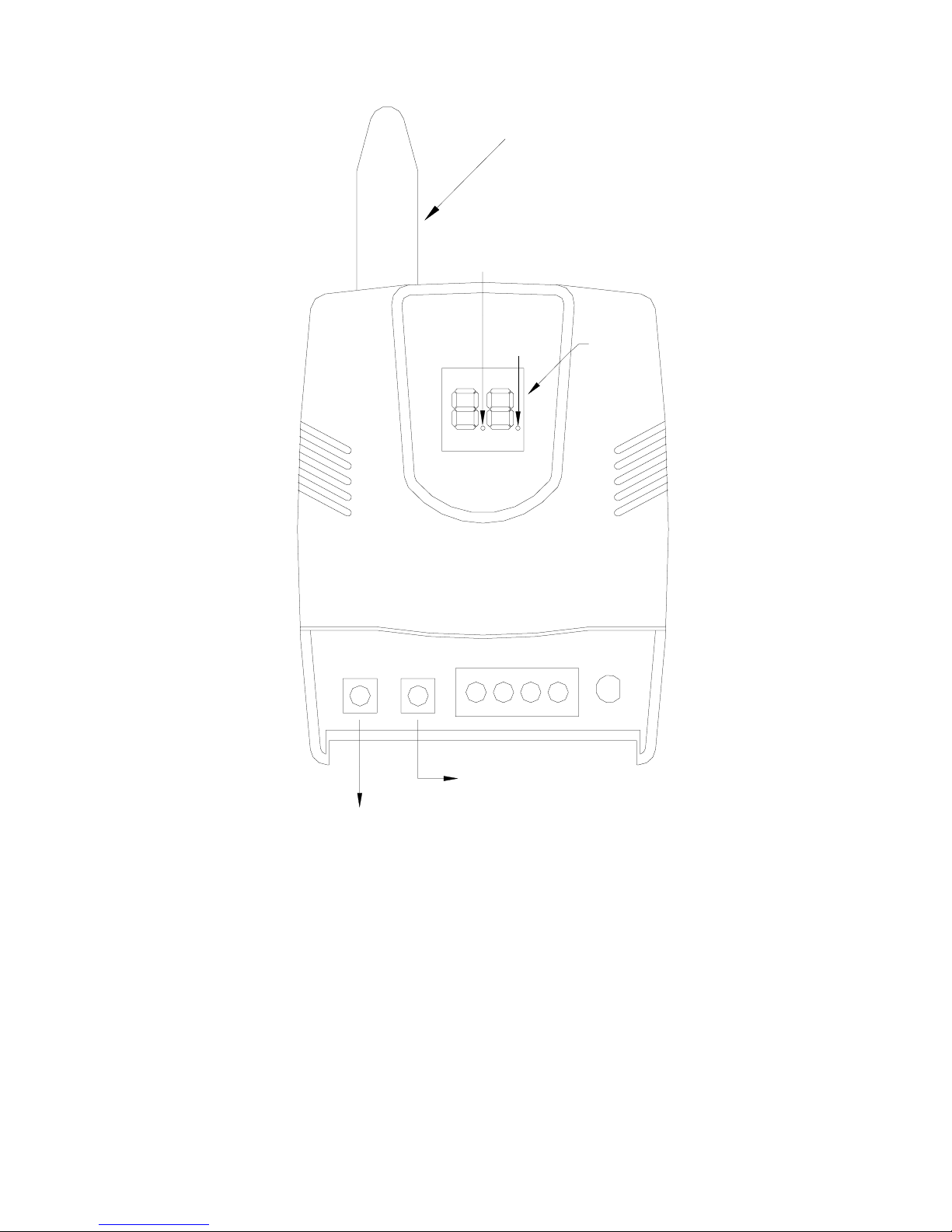
6. "1" will appear (1st transmitter address location). Trip the transmitter.
When the 45A00-1 receives the transmission, the 45A00-1 will display
the digit (transmitter address) with a dot on either side (the dots
indicate the transmitter's characteristics).
7. Press the Mode/Advance button to save the changes and proceed.
8. "2" will appear (2nd transmitter address location). Trip the transmitter.
When the 45A00-1 receives the transmission, the 45A00-1 will display
the digit (transmitter address) with a dot on either side (the dots
indicate the transmitter's characteristics).
9. Press the Mode/Advance button to save the changes and proceed.
10. Repeat for each transmitter address (1-64) until all transmitters have
been programmed.
11. After all transmitters have been programmed, replace the cover.
RESETTING OR REMOVING A TRANSMITTER
To replace an existing transmitter, reset the characteristics of a transmitter, or remove
a transmitter, enter Setup Mode as described under "Transmitter Setup" in this manual.
When the transmitter address location appears on the display, remove the transmitter's
characteristics by pressing the SET button until there are no dots (blinking or
otherwise) on either side of the address number. The transmitter in now removed.
To replace the transmitter, simply trip the new transmitter. When the 45A00-1
receives the transmission, the 45A00-1 will display the digit (transmitter address
location) with a dot on either side (the dots indicate the transmitter's characteristics).

7
RESET MEMORY
To erase all transmitters from memory and to reset to the factory default configuration,
press and hold both the Set and Mode/Advance switches simultaneously for 2 seconds.
The display will show "EE". If you choose to continue, press and hold the Set and
Mode/Advance switches simultaneously for 2 seconds once again. Memory is reset at
the end of the two seconds.
NOTE: If you choose not to reset memory at the "EE" display, don’t press any keys
for 10 seconds and the receiver will return to Run Mode.
CONNECTING TO OMNILT
Connect the receiver to the OmniLT controller using 4-conductor, 22-gauge or larger
wire as follows:
1. Connect the "A" and "B" terminals of the 45A00-1 to the “YEL”
(Yellow) and “GRN” (Green) terminals under the section marked
“CONSOLE” on the OmniLT controller (Yellow = A and Green = B).
2. Connect the "+12" and "GND" terminals of the 45A00-1 to the "RED"
and "BLK" (Black) terminals under the section marked “CONSOLE”
on the OmniLT controller (Red = +12V and Black = GND).

8
Controller
BLACK
GREEN
YELLOW
RED
GND+12V A B
D3
MODE SET
WIRELESS
RECEIVER
GREEN
YELLOW
BLACK
RED

9
OMNILT SETUP
A. At a console, select "Installer Setup" (press 9, installer code, then #). Press 2 for
“Zones”, and then press 1 # (“Wireless Receiver?” Yes = 1).
B. When connected to OmniLT, Zones 9-24 are the wireless receiver zones.
C. When connected to OmniLT, the receiver address on the 45A00-1 must be set to
"A1" and the number of addresses must be set to "n1".
D. OmniLT can handle up to 4 transmitters per zone.
The chart below shows the relationship of each wireless transmitter on the 45A00-1
Wireless Receiver to each zone on the OmniLT.
Zones on OmniLT Transmitter Numbers on Wireless Receiver
Zone 09 1 17 33 49
Zone 10 2 18 34 50
Zone 11 3 19 35 51
Zone 12 4 20 36 52
Zone 13 5 21 37 53
Zone 14 6 22 38 54
Zone 15 7 23 39 55
Zone 16 8 24 40 56
Zone 17 9 25 41 57
Zone 18 10 26 42 58
Zone 19 11 27 43 59
Zone 20 12 28 44 60
Zone 21 13 29 45 61
Zone 22 14 30 46 62
Zone 23 15 31 47 63
Zone 24 16 32 48 64
CONNECTING TO OMNI II, LUMINA, OMNIPRO II, OR LUMINA PRO
Connect the receiver to the Omni II, Lumina, OmniPro II, or Lumina Pro controller
using 4-conductor, 22-gauge or larger wire as follows:

10
1. Connect the "A" & "B" terminals of the 45A00-1 to the "A" & "B"
terminals under the section marked "CONSOLE" on the controller.
2. Connect the "+12" and "GND" terminals of the 45A00-1 to the "12V"
and "GND" terminals under the section marked “CONSOLE” on the
controller. Verify that the Status LED on the receiver is illuminated.
OMNI II AND LUMINA SETUP
A. At a console, select "Installer Setup" (press 9, installer code, then #). Press 2 for
“Zones”, and then press 1 # (“Wireless Receiver?” Yes = 1).
B. When connected to Omni II / Lumina, Zones 33-48 are the wireless receiver zones.
C. When connected to Omni II / Lumina, the receiver address on the 45A00-1 must
be set to "A1" and the number of addresses must be set to "n1".
D. Omni II can handle up to 4 transmitters per zone
The chart below shows the relationship of each wireless transmitter on the 45A00-1
Wireless Receiver to each zone on the Omni II / Lumina.
Zones on Omni II / Lumina Transmitter Numbers on Wireless Receiver
Zone 33 1 17 33 49
Zone 34 2 18 34 50
Zone 35 3 19 35 51
Zone 36 4 20 36 52
Zone 37 5 21 37 53
Zone 38 6 22 38 54
Zone 39 7 23 39 55
Zone 40 8 24 40 56
Zone 41 9 25 41 57
Zone 42 10 26 42 58
Zone 43 11 27 43 59
Zone 44 12 28 44 60
Zone 45 13 29 45 61
Zone 46 14 30 46 62
Zone 47 15 31 47 63
Zone 48 16 32 48 64

11
GREEN
YELLOW
BLACK
RED
MODE
D3
WIRELESS
RECEIVER
+12V
SET
GNDAB
Controller
BLACK
GREEN
YELLOW
RED

12
OMNIPRO II AND LUMINA PRO SETUP
A. OmniPro II and Lumina Pro can have two 45A00-1 Wireless Receivers connected.
When connected, the 45A00-1 is recognized as an Expansion Enclosure. Each
45A00-1 can handle up to 64 wireless zones, in groups of 16. Each group of 16
zones is considered 1 Expansion Enclosure (8 Expansion Enclosures maximum).
B. At a console, select “Installer Setup” (press 9, installer code, then #). Press 2 for
“Zones”. Press the down arrow once, then enter the number of expansion
enclosures (groups of 16 wireless zones) being used.
C. The wireless zones on the OmniPro II and Lumina Pro start on Zone 49 (if no
hardwire expansion enclosures are used).
D. The 45A00-1 address is set at 1 (A1) (if no hardwire expansion enclosures are
used).
E. If the OmniPro II / Lumina Pro has 1 hardwire expansion enclosure, the wireless
zones start on Zone 65. The 45A00-1 address is then set to 2 (A2).
F. If the OmniPro II / Lumina Pro has 2 hardwire expansion enclosures, the wireless
zones start on Zone 81. The 45A00-1 address is then set to 3 (A3).
G. If the OmniPro II / Lumina Pro has 3 hardwire expansion enclosures, the wireless
zones start on Zone 97. The 45A00-1 address in then set to 4 (A4).
H. If the OmniPro II / Lumina Pro has 4 hardwire expansion enclosure, the wireless
zones start on Zone 113. The 45A00-1 address is then set to 5 (A5).
I. If the OmniPro II/ Lumina Pro has 5 hardwire expansion enclosures, the wireless
zones start on Zone 129. The 45A00-1 address is then set to 6 (A6).
J. If the OmniPro II / Lumina Pro has 6 hardwire expansion enclosures, the wireless
zones start on Zone 145. The 45A00-1 address in then set to 7 (A7).
K. If the OmniPro II / Lumina Pro has 7 hardwire expansion enclosures, the wireless
zones start on Zone 161. The 45A00-1 address in then set to 8 (A8).

13
NOTE: If two 45A00-1 Wireless Receivers are connected, the first 45A00-1
must be addressed between 1-4 (A1-A4), and the second must be addressed
between 5-8 (A5-A8).
The charts below describe where each group of wireless transmitters (groups of 16) on
the 45A00-1 Wireless Receiver relates to each group of zones (groups of 16) on the
OmniPro II / Lumina Pro in accordance with the number of addresses assigned (n1-4).
Zones on OmniPro II / Lumina Pro (in groups of 16) when 45A00-1 is set
to address "A1"
Zones 49-64 Zones 65-80 Zones 81-96 Zones 97-
112
n1
Transmitters:
1-16, 17-32, 33-48, and
49-64
n2
Transmitters:
1-16 and 33-48
Transmitters:
17-32 and
49-64
n3
Transmitters:
1-16 and 49-64
Transmitters:
17-32
Transmitters:
33-48
n4
Transmitters:
1-16
Transmitters:
17-32
Transmitters:
33-48
Transmitters:
49-64
Zones on OmniPro II / Lumina Pro (in groups of 16) when 45A00-1 is set
to address "A5"
Zones 113-128 Zones 129-
144
Zones 145-
160
Zones 161-
176
n1
Transmitters:
1-16, 17-32, 33-48, and
49-64
n2
Transmitters:
1-16 and 33-48
Transmitters:
17-32 and
49-64
n3
Transmitters:
1-16 and 49-64
Transmitters:
17-32
Transmitters:
33-48
n4
Transmitters:
1-16
Transmitters:
17-32
Transmitters:
33-48
Transmitters:
49-64

14
HAI CONTROLLER INDICATIONS
When the condition of a transmitter changes state, the HAI console will display that
condition as follows:
Transmitter Condition HAI Console Display
When a transmitter (zone) is violated Zone Name "NOT RDY"
When a cover is removed from a transmitter Zone Name "NOT RDY"
When a supervisory failure is reported Zone Name "TRBL NOW"
When a battery low is reported Zone Name "HAD TRBL"
FEDERAL COMMUNICATIONS COMMISSION (FCC) STATEMENT
This equipment has been tested to FCC requirements and has been found acceptable for use. The FCC
requires the following statement for your information: This equipment generates and uses radio
frequency energy and if not installed and used properly, that is, in strict accordance with the
manufacturer's instructions, may cause interference to radio and television reception. It has been type
tested and found to comply with the limits for a Class B computing device in accordance with the
specifications in Part 15 of FCC Rules, which are designed to provide reasonable protection against
such interference in a residential installation. However, there is no guarantee that interference will not
occur in a particular installation. If this equipment does cause interferences to radio or television
reception, which can be determined by turning the equipment off and on, the user is encouraged to try
to correct the interference by one or more of the following measures:
• If using an indoor antenna, have a quality outdoor antenna installed.
• Reorient the receiving antenna until interference is reduced or eliminated
• Move the receiver away from the control/communicator.
• Move the antenna leads away from any wire runs to the control/communicator.
• Plug the control/communicator into a different outlet so that it and the receiver are on different branch
circuits.
If necessary, the user should consult the dealer or an experienced radio/television technician for
additional suggestions. The user or installer may find the following booklets prepared by the Federal
Communications Commission helpful: “Interference Handbook”. This booklet is available from the
U.S. Government Printing Office, Washington, DC 20402. The user shall not make any changes or
modifications to the equipment unless authorized by the installation instructions or User’s Manual.
Unauthorized changes or modifications could void the user’s authority to operate the equipment.

To enter Setup Mode, press and hold the Mode/Advance
switch for 2 seconds.
DISPLAY DESCRIPTION SET SWITCH MODE/ADVANCE
SWITCH
A 1 Enter the receiver
address
Changes the current
address (1-8)
Advances to the next
item
n 1 Enter number of
addresses
Changes number of
addresses (1-4)
Advances to the next
item
1 Displays the status of
transmitter 1
Changes characteristics
of transmitter
Advances to the next
transmitter
2 Displays the status of
transmitter 2
Changes characteristics
of transmitter
Advances to the next
transmitter
3 Displays the status of
transmitter 3
Changes characteristics
of transmitter
Advances to the next
transmitter
Characteristics of Transmitters:
DISPLAY MODE
LED
TYPE LED DESCRIPTION OF THE DISPLAY
1 OFF OFF No transmitter is programmed at this address
1*OFF BLINKS This transmitter is not supervised and doesn't
send restore transmissions
.1*ON BLINKS This transmitter is not supervised but sends
restore transmissions
1. OFF ON This transmitter is supervised but doesn't send
restore transmissions
.1. ON ON This transmitter is supervised and sends
restore transmissions
To reset memory, press and hold the Set and Mode/Advance
switches together for 2 seconds.
DISPLAY DESCRIPTION SET SWITCH
E E Erase EEPROM ?
(Reset Memory)
Press and hold Set & Mode/Advance switches
together for 2 seconds
Table of contents
Popular Receiver manuals by other brands

Clear One
Clear One DIALOG 10 quick start guide

Sky Master
Sky Master DCI 9410 operating instructions

Black Box
Black Box AVX-VGA-TP-TX user manual

SHENZHEN GUIYUAN INDUSTRY DEVELOPMENT
SHENZHEN GUIYUAN INDUSTRY DEVELOPMENT S1X-DC06 quick start guide

A-Neuvideo
A-Neuvideo ANI-304RX instruction manual

Sky Master
Sky Master DS 66 operating instructions