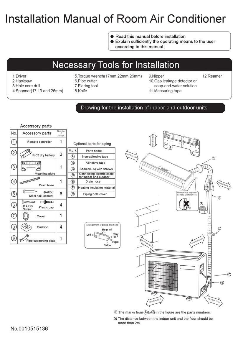
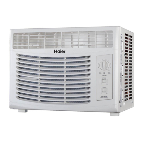
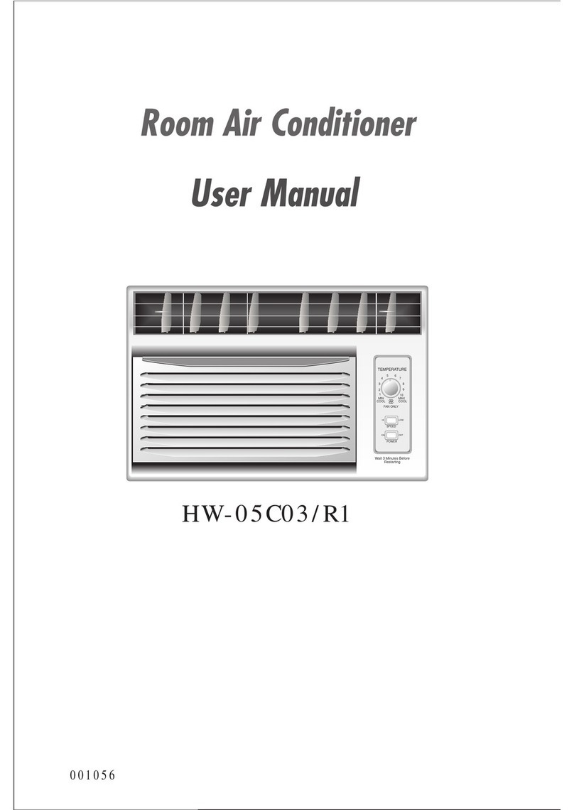
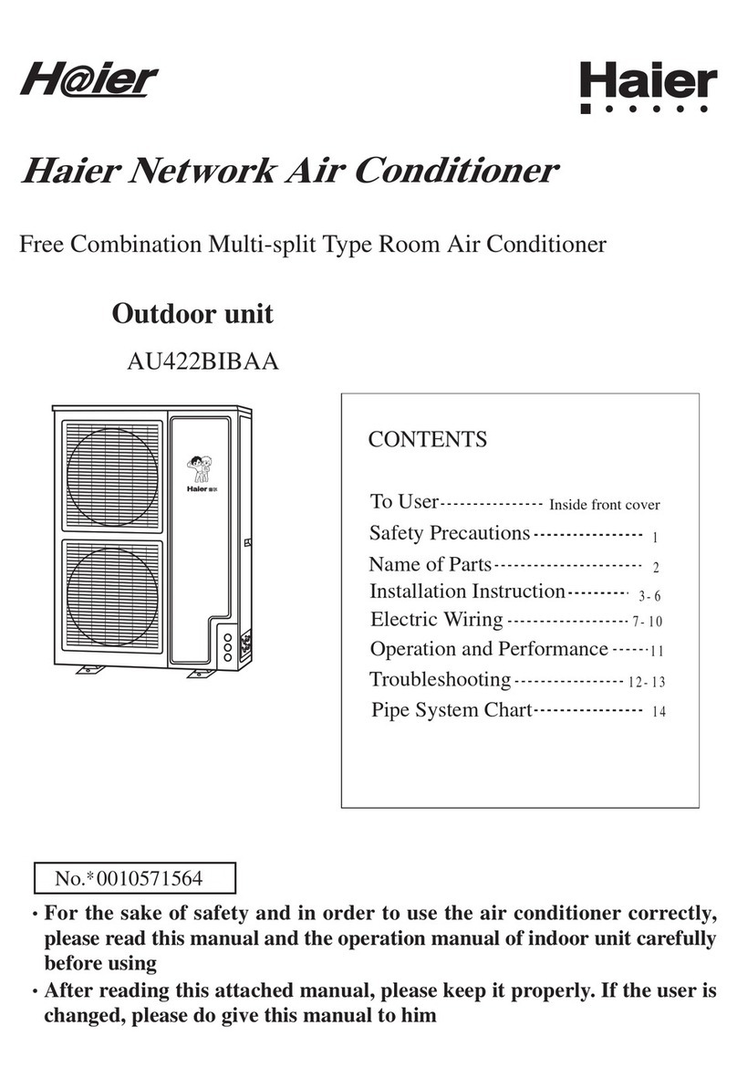
Haier HSU-18HEA03/R2(DB)-I User manual

SERVICE MANUAL
DC Inverter E-Series
Model No. HSU-18HEA03/R2(DB)-I
©2008 (Qingdao Haier Air Conditioner General corp.,Ltd)
All right reserved .Unauthorized copying and distribution is a violation of law
Haier Group
This service information is designed for experienced repair technicians only and is not designed for use by the general public.
It does not contain warnings or cautions to advise non-technical individuals of potential dangers in attempting to service a product.
Products powered by electricity should be serviced or repaired only by experienced professional technicians. Any attempt to service or
repair the product or products dealt with in this service information by anyone else could result in serious injury or death
WARNING
Wall mounted Type
Order No.AC0902S004V0

HSU-18HEA03/R2(DB)-I Table of Contents
Domestic Air Conditioner
Table of Contents
1. Introduction 1
1.1 Safety Cautions 1
2. List of Functions 5
6
4. Printed Circuit Board Connector Wiring Diagram 8
4.1 Indoor unit Connectors 8
4.2 Outdoor unit 9
5. Funcitions and Control 12
12
5.2 The control system of outdoor unit 17
5.3 Value of Thermistor 22
32
32
6.2 Instruction 32
7 Service Diagnosis 58
58
7.2 Problem Symptoms and Measures 58
7.3 Error Codes and Description indoor display 58
8 Installation 73
9. Removal Procedure 81
9.1 The removal procedure of Indoor 81
9.2 The removal procedure of Outdoor 91
10. Appendix 104
104
106
107
110
11.Decription of coding rules of unit model

HSU-18HEA03/R2(DB)-I Introduction
Domestic Air Conditioner
1
1. Introduction
1.1 Safety Cautions
Be sure to read the following safety cautions before conducting repair work.
The caution items are classified into “Warning” and “Caution”. The “Warning” items are especially
important since they can lead to death or serious injury if they are not followed closely. The “Caution”
items can also lead to serious accidents under some conditions if they are not followed. Therefore, be
sure to observe all the safety caution items described below.
About the pictograms
UThis symbol indicates an item for which caution must be exercised.
The pictogram shows the item to which attention must be paid.
This symbol indicates a prohibited action.
The prohibited item or action is shown inside or near the symbol.
zThis symbol indicates an action that must be taken, or an instruction.
The instruction is shown inside or near the symbol.
After the repair work is complete, be sure to conduct a test operation to ensure that the equipment
operates normally, and explain the cautions for operating the product to the customer.
1.1.1 Caution in Repair
Warning
Be sure to disconnect the power cable plug from the plug socket before disassembling the
equipment for a repair.
Working on the equipment that is connected to a power supply can cause an electrical
shook.
If it is necessary to supply power to the equipment to conduct the repair or inspecting the
circuits, do not touch any electrically charged sections of the equipment.
If the refrigerant gas discharges during the repair work, do not touch the discharging
refrigerant gas.The refrigerant gas can cause frostbite.
When disconnecting the suction or discharge pipe of the compressor at the welded section,
UHOHDVHWKHUHIULJHUDQWJDVFRPSOHWHO\DWDZHOOYHQWLODWHGSODFH¿UVW
If there is a gas remaining inside the compressor, the refrigerant gas or refrigerating
machine oil discharges when the pipe is disconnected, and it can cause injury.
If the refrigerant gas leaks during the repair work, ventilate the area. The refrigerant gas can
JHQHUDWHWR[LFJDVHVZKHQLWFRQWDFWVÀDPHV
The step-up capacitor supplies high-voltage electricity to the electrical components of the
outdoor unit.
Be sure to discharge the capacitor completely before conducting repair work.A charged
capacitor can cause an electrical shock.
Do not start or stop the air conditioner operation by plugging or unplugging the power cable
plug.
Plugging or unplugging the power cable plug to operate the equipment can cause an
HOHFWULFDOVKRFNRU¿UH

HSU-18HEA03/R2(DB)-I Introduction
Domestic Air Conditioner
2
Warning
Do not repair the electrical components with wet hands. Working on the equipment with wet
hands can cause an electrical shock.
Do not clean the air conditioner by splashing water. Washing the unit with water can cause
an electrical shock.
Be sure to provide the grounding when repairing the equipment in a humid or wet place, to
avoid electrical shocks.
Be sure to turn off the power switch and unplug the power cable when cleaning the
equipment. Theinternal fan rotates at a high speed, and cause injury.
Do not tilt the unit when removing it. The water inside the unit can spill and wet the furniture
DQGÀRRU
Be sure to check that the refrigerating cycle section has cooled down sufficiently before
conducting repair work. Working on the unit when the refrigerating cycle section is hot can
cause burns.
Use the welder in a well-ventilated place. Using the welder in an enclosed room can cause
R[\JHQGH¿FLHQF\
1.1.2 Cautions Regarding Products after Repair
Warning
Be sure to use parts listed in the service parts list of the applicable model and appropriate
tools to conduct repair work. Never attempt to modify the equipment. The use of
LQDSSURSULDWHSDUWVRUWRROVFDQFDXVHDQHOHFWULFDOVKRFNH[FHVVLYHKHDWJHQHUDWLRQRU¿UH
When relocating the equipment, make sure that the new installation site has sufficient
strength to withstand the weight of the equipment.
If the installation site does not have sufficient strength and if the installation work is not
conducted securely, the equipment can fall and cause injury.
Be sure to install the product correctly by using the provided standard installation frame.
Incorrect use of the installation frame and improper installation can cause the equipment to
fall, resulting in injury.
For integral
units only
Be sure to install the product securely in the installation frame mounted on a window frame.
If the unit is not securely mounted, it can fall and cause injury.
For integral
units only

HSU-18HEA03/R2(DB)-I Introduction
Domestic Air Conditioner
3
Warning
Be sure to use an exclusive power circuit for the equipment, and follow the technical
standards related to the electrical equipment, the internal wiring regulations and the
instruction manual for installation when conducting electrical work.
Insufficient power circuit capacity and improper electrical work can cause an electrical
VKRFNRU¿UH
%HVXUHWRXVHWKHVSHFL¿HGFDEOHWRFRQQHFWEHWZHHQWKHLQGRRUDQGRXWGRRUXQLWV0DNH
the connections securely and route the cable properly so that there is no force pulling the
cable at the connection terminals.
,PSURSHUFRQQHFWLRQVFDQFDXVHH[FHVVLYHKHDWJHQHUDWLRQRU¿UH
When connecting the cable between the indoor and outdoor units, make sure that the
terminal cover does not lift off or dismount because of the cable.
If the cover is not mounted properly, the terminal connection section can cause an electrical
VKRFNH[FHVVLYHKHDWJHQHUDWLRQRU¿UH
Do not damage or modify the power cable.
Damaged or modified power cable can cause an electrical shock or fire. Placing heavy
items on the power cable, and heating or pulling the power cable can damage the cable.
'RQRWPL[DLURUJDVRWKHUWKDQWKHVSHFL¿HGUHIULJHUDQW5$5LQWKHUHIULJHUDQW
system.
If air enters the refrigerating system, an excessively high pressure results, causing
equipment damage and injury.
If the refrigerant gas leaks, be sure to locate the leak and repair it before charging the
refrigerant. After charging refrigerant, make sure that there is no refrigerant leak.
If the leak cannot be located and the repair work must be stopped, be sure to perform
pump-down and close the service valve, to prevent the refrigerant gas from leaking into the
room. The refrigerant gas itself is harmless, but it can generate toxic gases when it contacts
ÀDPHVVXFKDVIDQDQGRWKHUKHDWHUVVWRYHVDQGUDQJHV
When replacing the coin battery in the remote controller, be sure to disposed of the old
battery to prevent children from swallowing it.
If a child swallows the coin battery, see a doctor immediately.
Caution
Installation of a leakage breaker is necessary in some cases depending on the conditions of
the installation site, to prevent electrical shocks.
Do not install the equipment in a place where there is a possibility of combustible gas leaks.
,IDFRPEXVWLEOHJDVOHDNVDQGUHPDLQVDURXQGWKHXQLWLWFDQFDXVHD¿UH
Be sure to install the packing and seal on the installation frame properly. If the packing and
VHDODUHQRWLQVWDOOHGSURSHUO\ZDWHUFDQHQWHUWKHURRPDQGZHWWKHIXUQLWXUHDQGÀRRU
For integral
units only

HSU-18HEA03/R2(DB)-I Introduction
Domestic Air Conditioner
4
1.1.3 Inspection after Repair
Warning
Check to make sure that the power cable plug is not dirty or loose, then insert the plug into
a power outlet all the way.
,IWKHSOXJKDVGXVWRUORRVHFRQQHFWLRQLWFDQFDXVHDQHOHFWULFDOVKRFNRU¿UH
If the power cable and lead wires have scratches or deteriorated, be sure to replace them.
'DPDJHGFDEOHDQGZLUHVFDQFDXVHDQHOHFWULFDOVKRFNH[FHVVLYHKHDWJHQHUDWLRQRU¿UH
Do not use a joined power cable or extension cable, or share the same power outlet with
other electrical appliances, since it can cause an electrical shock, excessive heat generation
RU¿UH
Caution
Check to see if the parts and wires are mounted and connected properly, and if the
connections at the soldered or crimped terminals are secure. Improper installation and
FRQQHFWLRQVFDQFDXVHH[FHVVLYHKHDWJHQHUDWLRQ¿UHRUDQHOHFWULFDOVKRFN
If the installation platform or frame has corroded, replace it. Corroded installation platform or
frame can cause the unit to fall, resulting in injury.
Check the grounding, and repair it if the equipment is not properly grounded. Improper
grounding can cause an electrical shock.
Be sure to measure the insulation resistance after the repair, and make sure that the
UHVLVWDQFHLV0RKPRUKLJKHU
Faulty insulation can cause an electrical shock.
Be sure to check the drainage of the indoor unit after the repair.
)DXOW\GUDLQDJHFDQFDXVHWKHZDWHUWRHQWHUWKHURRPDQGZHWWKHIXUQLWXUHDQGÀRRU

HSU-18HEA03/R2(DB)-I List of Functions
Domestic Air Conditioner
5
2. List of Functions
Category Functions
HSU-18HEA03/R2(DB)-I
Healthy negative ion make your room full of an abundance natural negative ions. Y
Child lock Avoid the child's wrong operation on the remote controller Y
.N
24Hour timer Use the timer function to set on,or off,or from on to off,or from off to
on Y
Auto restart automatic return to previous operation conditions after asundden
power blackout Y
Easy clean design The panel is easy to wash and the airflow vents can be detached
easily Y
Intelligent air directly Y
Catches most small particles and remove unpleasant odors
effectively. Y
Sleep mode
The setting temprature and the indoor noise can be adjusted to a
more comfortable level when you set the "sleep mode"during night
sleep
Y
4 Fan setting Slect the fan speed LO,MED,HI,AUTO Y
Auto mode Y
Power mode Quick cooling or heating Y
Soft mode lower noise operation condition Y
N
Constant temperature Make dehumidifying in the room while keeping the constant
temperature inside N
Note: Y : Holding Functions
N : No Functions

HSU-18HEA03/R2(DB)-I
Domestic Air Conditioner
6
Model
HSU-18HEA03/R2(DB)-I
Cooling Heating
Capacity
Rated(Min.~Max.)
kW 5.00(0.95~5.5) 5.22
Btu/h
17070(3240~1870)
18750
kcal/h 4300 4489
Mositure Removal L/h 2.0 —
Running Current(Read) A 7.13 6.88
Power Consumption
Read(Min.~Max.) W1580(270-1950) 1600(350~2200)
Power Factor % 98 98
COP Rated (Min.~Max.) W/W 3.16 3.26
Piping
Connctions
Liquid mm ĭ
Gas mm ĭ
Drain mm ĭ
Heat Insulation Both Liquid and Gas Pipes
Max. Interunit Piping Length m 25
Max. Interunit Height
Difference m15
Chargeless m 10
Amount of Additional
Charge of Refrigerant g/m 20
Indoor Unit
Front Panel Color White
Air Flow Rate
m3/
min(cfm)
H 13.3
M 12.1
L 10.9
SL 6.0
14.1
12.9
11.7
6.8
Fan
Type Cross Flow Fan
Motor Output
W40
Speed
Steps
Steps, Auto4
Air Direction Control
Horizontal, Downward
Air Filter
Removable/ Washable/ Mildew Proff
Running Current (Rated)
A 0.16 0.16
Power Consumption (Rated)
W25 25
Power Factor
%96 96
Temperature Control Microcomputer Control
Dimensions (H×W×D)
mm
182×938×265
Packaged Dimensions (H×W×D)
mm
275×1013×330
Weight
kg
10.9
Gross Weight
kg
12.6
Operation Sound H/M/L
dBA 44/41/38
Sound Power
H
dBA 54
44/41/38
54

HSU-18HEA03/R2(DB)-I
Domestic Air Conditioner
7
Outdoor Unit
Casing Color Ivory White
Compressor
Type
Sroll Compressor
Model 5CS130×CC03
Motor Output W 1650
Refrigerant Oil
Model SRB68A
Charge L 0.48
Refrigerant
Model R410A
Charge kg 1.00
Air Flow Rate m3/min 36.6
cfm
Fan Type Propeller
Motor Output
W35
Running Current (Rated)
A7.13 6.88
Power Consumption (Rated)
W 1580 1600
Power Factor
%98 98
Starting Current
A
10
Dimensions (H×W×D)
mm
820×682×310
Packaged Dimensions (H×W×D)
mm
949×745×406
Weight
kg
47
Gross Weight
kg
50
Operation
Sound H/L
dBA
Sound
Power
H
dBA
Note: The data are based the conditions shown in the table below.
Cooling Heating Piping Length
Indoor: 27°CDB/19°CDB
Outdoor: 27°CDB/19°CDB
Indoor: 20°CDB
Outdoor: 7°CDB/6°CDB
7.5m
Conversion Formulae
kcal/h=kW×860
Btu/h=kW×3414
cfm=m3/min×35.3
HSU-18HEA03/R2(DB)-I
1294
52
62

HSU-18HEA03/R2(DB)-I Connector Wring Diagram
Domestic Air Conditioner
8
4. Printed Circuit Board Connector Wiring Diagram
4.1 Indoor unit Connectors
Connectors
PCB(1) (Control PCB)
1) CN601 Connector for fan motor
2) CN9 Connector for STEP motor
3) CN8 Connector for heat exchanger thermistor and Room temperature thermistor
4) CN3 Connector for communicate wire and N wire
5) CON2,CON1Connector for ions generator
6) CN6 Connector for display board
7) CON3 Connector for L wire
8) CON5 Connector for ground
Note: Other designations
PCB(1) (INdoor Control PCB)
1) FUSE1 Fuse 3.15A/250VAC

HSU-18HEA03/R2(DB)-I Connector Wring Diagram
Domestic Air Conditioner
9
4.2
Connectors
PCB(1) (Control PCB)
1) CN1,CN2 Connector for power N and L
2) CN3 Connector for ground
3) CN6,CN7 Connector for terminal block
4) CN9,CN10 Connector for CN2,CN1 on the module board
5) CN11 Connector for four way valve coil
6) CN12 Connector for fan motor
7) CN15 Connector for electric expansion valves
8) CN17,CN18,CN19, CN21 Connector for thermistors
9) CN23 Connector for DC POWER 15Vand 5V to the module board
10) CN24 Connector for communicate between the control board and the module board
11) CN28,CN25 Connector to P and N of the module board
12) CN36 Connector for communicate between indoor and outdoor unit
PCB(2) (module PCB)
CN10 Connector for the DC power 5V and 15V form the control PCB
CN11 Connector for communicate between the control board and the module board
P( CN8), N(CN9) Connector for CN2 DQG&1 on the control board
LI (CN3),LO(CN4) Connector for reactor
AC_L(CN1),AC_N(CN2) Connector for CN ,CNon the control board
CN5(U), CN6(V), CN7(W) connector for the compressor
Note: Other Designations
PCB(1) (Control PCB)
1) FUSE 1, Fuse (25A,250VAC)
/('NHHSOLJKWUHSUHVHQWDWLYHQRUPDOLINHHSÀDVKLQWHUYDOUHSUHVHQWDWLYHWURXEOHAlarm
3) RV1,RV2,RV3 Varistor
Outdoor Unit

HSU-18HEA03/R2(DB)-I Connector Wring Diagram
Domestic Air Conditioner
10
CN36
CN17
CN28
CN23
CN18
CN9
CN3
CN10
CN11
CN15
CN24 CN25
CN19
CN21
CN1
CN2
CN12
CN6 CN7

HSU-18HEA03/R2(DB)-I Connector Wring Diagram
Domestic Air Conditioner
11
CN5
CN6
CN7
CN8
CN9
CN10
CN3 CN1 CN2 CN4
CN11

HSU-18HEA03/R2(DB)-I Funcitions and Control
Domestic Air Conditioner
12
5. Funcitions and Control
0DLQIXQFWLRQVDQGFRQWUROVSHFL¿FDWLRQRILQGRRUXQLW
5.1.2 Cooling operation mode
Temperature control range: 16°C---30°C
Temperature difference: ±1°C
* Control features: When Tr(input airflow)>Ts(set temperature)°C, the compressor will be opened,the
indoor fan will operate at the set speed and the mode signal will be sent to the outdoor system. When
Tr(input DLUÀRZ< Ts(set temperature)°C, the compressor will be opened,the indoor fan will operate at
the set speed and the mode signal will be sent to the outdoor system. The system will keep the original
status if Tr= Ts.
$LUÀRZVSHHGFRQWUROWHPSHUDWXUHGLfference 1°C)
Automatic: When Tr>=Ts+3°C, high speed.
When Ts+1°C=<Tr<Ts+3°C, medium speed
When Tr<Ts+1°C, low speed
When the sensor is off, low speed
When the DLUÀRZ speed has no delay from the high to low switching, the speed should be delayed for 3
minutes (remain at high speed for 3 minutes.) before the next switch.
'HKXPLGL¿FDWLRQPRGH
* temperature control range: 16---30°C
* temperature difference: ±1°C
Control feature: send the dehumidify signal to the outdoor system.
When Tr>Ts+2°C , the compressor will be turned on, the indoor fan will operate at the set speed.
When Tr is between the Ts and Ts+2°C , the outdoor system will operate at the high dehumidify frequency
5.1.1 automatic run mode
When the running mode is turned to automation after starting the system, the system will first
determine the running mode according to the current room temperature and then will run according to
the determined mode. Tr in the following selection conditions means room temperature, Ts means
setting temperature, Tp means temperature of indoor coil pipe
Tr 23 Choose Cooling Mode
Tr 23 Choose Heating Mode
After turning to the automation mode, the running mode can be switched between
cooling mode, fan mode and heating mode according to the change of the indoor
ambient temperature. But the automatic conversion between cooling mode and
heating mode must be conducted after 15 minutes.

HSU-18HEA03/R2(DB)-I Funcitions and Control
Domestic Air Conditioner
13
for 10 minutes and then at the low dehumidify mode for six minutes. The indoor fan will operate at low
speed.
When Tr< Ts, the outsystem will be stopped, the indoor fan will be stopped for 3 minutes and then turned
to the low speed option.
$OOWKHIUHTXHQF\FRQYHUVHVKDYHD&GLIIHUHQFH
* Wind speed control: Automatic:
:KHQ7U! 7V&KLJKVSHHG
:KHQ7V&7U7V&PHGLXPVSHHG
:KHQ7V&7U7V&ORZVSHHG
:KHQ7U7V&OLJKWVSHHG
If the outdoor fan stopped, the indoor fan will be paused for 3 minutes.
If the outdoor fan stopped for more than 3 minutes and the outdoor system still operates, the system will
be changed into light speed mode.
:KHQWKHDLUÀRZVSHHGKDVQRGHOD\IURPWKHKLJKWRORZVZLWFKLQJWKHVSHHGVKRXOGEHGHOD\HGIRU
minutes (remain at high speed for 3 minutes.) before the next switch.
0DQXDO:KHQWKHVHQVRULVRIIRU7U7V&WKHPDQXDORSHUDWLRQFDQQRWEHPDGHREOLJDWRU\
automatic operation.)
5.1.4 Heating operation mode
WHPSHUDWXUHFRQWUROUDQJH&
WHPSHUDWXUHGLIIHUHQFH&
* control feature: the temperature compensation is automatically added and the system will send the
heating signals to the outdoor system.
If Tr Ts, the outdoor compressor is turned on, the indoor fan will be at the cold air proof mode.
If Tr>Ts+, the outdoor system is turned off, the indoor fan will be at the heat residue sending mode.
If Tr<Ts+, the outdoor system will be turned on again, the indoor fan will be at the cold air proof mode.
*Indoor fan control
manual control: You can choose high, medium, low and automatic speed control.
Automatic: When Tr<Ts, high speed.
:KHQ7V 7U 7V&PHGLXPVSHHG
:KHQ7U!7V&ORZVSHHG
:KHQWKHDLUÀRZVSHHGKDVQRGHOD\IURPWKHKLJKWRORZVZLWFKLQJWKHVSHHGVKRXOGEHGHOD\HGIRU
minutes (remain at high speed for 3 minutes.) before the next switch.
*Airgate location control: the location for the airgate can be set according to your needs.
Coldair proof operation
1. The indoor operation within 4 minutes after the start up is as the following diagram, the air speed can
EHUDLVHGRQO\DIWHUWKHVSHHGKDVUHDFKHGDFHUWDLQOHYHO
PLQXWHVDIWHUWKHVWDUWXSRIWKHLQGRRUIDQWKHOLJKWDLUÀRZDQGWKHORZDLUÀRZZLOOEHWXUQHGWRWKH
VHWVSHHGDLUÀRZ
3. In the cold air proof operation, the fan won’t stop after the start up.
4. During the cold air proof operation, the indoor system will continuously send ‘indoor high speed’signals
to the outdoor system.
5.1.5 Strength operation
DWKHV\VWHPHQWHUVWKHPRGHDIWHUUHFHLYLQJWKHµVWUHQJWKVLJQDO
Send strength operation signal to the outdoor system.

HSU-18HEA03/R2(DB)-I Funcitions and Control
Domestic Air Conditioner
14
Strength operation for 15 minutes.
7KHVWUHQJWKRSHUDWLRQVWRSVRU¿QLVKHVDIWHUWKHPLQXWHV
7KHPRGHFKDQJH¿QLVKHVWKHVWUHQJWKRSHUDWLRQ
(QWHULQJµPXWH¶\RXFDQKDYHQRUPDORSHUDWLRQRUVLJQDOFRQWUROVXFKDVWLPLQJWR¿QLVKWKHVWUHQJWK
operation.
When the system is at the automatic option with the strength/ mute function, if the system enters the
cooling mode, the cooling strength/ mute function will be offered; if the system enters the heating mode,
WKHQWKHKHDWLQJVWUHQJWKPXWHIXQFWLRQZLOOEHRIIHUHGLIWKHV\VWHPHQWHUVWKHDLUÀRZPRGHWKHUHZLOO
be no strength/ mute function.
5.1.6 Mute operation
7KHV\VWHPHQWHUVWKHPRGHDIWHUUHFHLYLQJWKHµPXWHVLJQDO
D0XWHKHDWLQJWKHDLUÀRZVSHHGLVVOLJKWWKHV\VWHPVHQGVWKHPXWHVLJQDOWRWKHRXWGRRUV\VWHP
E0XWHFRROLQJWKHDLUÀRZVSHHGLVVOLJKWWKHV\VWHPVHQGVWKHPXWHVLJQDOWRWKHRXWGRRUV\VWHP
:KHQWKHFRPSUHVVRURSHUDWHVWKHDLUÀRZVSHHGLVPXWHVSHHG((3520LVDGDSWDEOH
0XWHRSHUDWLRQFDQQRWZRUNXQGHUWKHGHPRLVWXULQJDQGDLUÀRZVHQGLQJRSHUDWLRQ
5.1.7 Air refreshing
$IWHUUHFHLYLQJWKHVLJQDOIURPWKHUHPRWHFRQWURO+9VHULHVWKHEDFNJURXQGOLJKWRIWKHµKHDOWK¶ORJR
LVJUHHQ+6VHULHVWKHµKHDOWK¶LQGLFDWRUZLOOEHOLJKWHG,IWKHIDQRSHUDWHVWKHQHJDWLYHLRQJHQHUDWRU
RSHUDWHVWRUHDOL]HWKHQHJDWLYHVHQGLQJIXQFWLRQ
,IWKHLQGRRUIDQVWRSVWKHQHJDWLYHLRQJHQHUDWRULVWXUQHGRII
:KHQWKHQHJDWLYHLRQJHQHUDWRULVWXUQHGRIILIWKHDLUUHIUHVKLQJV\VWHPLVWXUQHGRQWKHQHJDWLYHLRQ
generator will be turned on when the fan operates.
5.1.8 Timing
You can set 24 hours’ on/off timing accordingly. After the setting, the timing indicator will be lightened.
$OVRWKHOLJKWZLOOEHWXUQLQJRIIDIWHUWKHWLPLQJLV¿QLVKHG7KHIROORZLQJVDUHVHYHUDOWLPLQJPHWKRGV
System /on timing: The timing indicator will be lightened and the indoor system is under the waiting
PRGH7KHOLJKWZLOOEHWXUQHGRIIZKHQWKHWLPLQJLV¿QLVKHGDQGWKHUHVWRIWKHV\VWHPZLOORSHUDWHXQGHU
a normal condition. The timing starts since the last reception of the timing singal.
<RXFDQKDYHWKHGRUPDF\VHWWLQJXQGHUWKHWLPLQJPRGHWKHRUGHURI\RXUVHWWLQJVZLOOEHRSHUDWHG
according to the timing settings.
System /off timing: When the system is turned on, the timing indicator is lightened, the rest of the
system will operated under a normal condition. When set time comes, the indicator light will be turned off
DQGWKHV\VWHPZLOOEHWXUQHGRII,I\RXKDYHVHWWKHGRUPDQWIXQFWLRQVWKHRUGHURI\RXUVHWWLQJVZLOOEH
operated according to the timing settings.
System /on and off timing: The settings will be completed according to the orders.
5.1.9 Dormant operation
7KHGRUPDQWWLPLQJLVDQHLJKWKRXUVXQDGDSWDEOHRQH7KHWLPLQJVLJQVDUHVKRZQRQWKH9VHULHV
board. (RC series show the dormant signal, the timing light is lighted on the 6 lights board).
5.1.9.1 Under the cooling/ demoisture operation, after the setting of the dormant operation, the set
temperature will be raised for 1 centigrade after 1 hour’s operation and will be raised for 1 centigrade 1
hour later. The system will keep this status for 6 hours and then close.

HSU-18HEA03/R2(DB)-I Funcitions and Control
Domestic Air Conditioner
15
5.1.9.2 Under the heating mode, after the setting of the dormant operation, the et temperature will fall 2
centigrades after 1 hour’s operation and will fall 2 centigrades 1 hours later. 3 hours after the preceding
operations, the set temperature will be raised for 1 centigrade and the system will keep this status for 3
hours and then close down.
5.1.9.3 During the dormant time, except the change of the system mode or a new press on the dormant
VHWWLQJNH\VWKHWLPLQJRIWKHKRXUVGRUPDQF\ZLOOWDNHWKH¿UVWWLPLQJDVWKHVWDUWWLPHDQ\SUHVVHVRQ
other keys will not affect the original timing.
5.1.9.4 Indoor fan control under the dormant operation.
If the indoor fan is at the high speed before the dormant operation setting, the speed will be turned to
medium after the setting. If the fan is at the medium speed before the dormant setting, the speed will be
turned to low after the setting. If the fan is at the low speed before the dormant setting, the speed will not
change.
5.1.10 Urgent on/off input
3UHVVWKHXUJHQF\EXWWRQWKHEX]]HUZLOOULQJ7KHV\VWHPZLOOHQWHUWKHDXWRPDWLFPRGHLI\RXGRQ¶WSUHVV
the button for more than 5 seconds.
Under the system off mode, if you press the urgency key for 5 to 10 seconds, the system will start the
test operation.
Under the system off mode, If you press the urgency key for 10 to 15 seconds, the display screen will
show the resume of the last malfunction.
If the system is under operation, the press on the urgency key will stop it.
Under the system off mode, the display screen will show automatic running sign.
8QGHUWKHV\VWHPRIIPRGHWKHV\VWHPZLOOQRWUHFHLYHWKHUHPRWHFRQWUROVLJQDOLIWKHSUHVVRQWKH
urgency key doesn’t last for 15 seconds or if the key is loosened.
Urgency operation: If you press the urgency key for less than 5 seconds, the buzzer will ring when you
press the on/off key. The system will enter the urgency operation when the urgency key is loosened. The
urgency operation is fully automatic.
Test operation.
The inlet temperature sensor doesn’t work, the indoor fan and the indoor air direction board motor works
V\QFKURQLFDOO\+LJKVSHHGDLUÀRZFRROLQJRXWGRRUV\VWHPRQHWFZLOOVHQGWKHDPELHQWWHPSHUDWXUH
centigrade and coil temperature 16 centigrade information to the outdoor system.
Test operation
7KHGHIURVWSURWHFWLRQRIWKHHYDSRUDWRUGRHVQ¶WZRUN
The temperature control doesn’t work.
7KHWHVWRSHUDWLRQZLOOEH¿QLVKHGLQPLQXWHV
7KHWHVWRSHUDWLRQFDQEHVWRSSHGE\WKHUHODWLYHFRPPDQGVIURPWKHUHPRWHFRQWURO
5.1.11 Low load protection control
,QRUGHUWRSUHYHQWWKHIURVWLQJRIWKHLQGRRUKHDWLQWHUDFWLRQGHYLFHWKHRXWGRRUV\VWHPZLOOEHVWRSSHG
if the indoor heat interaction temperature is below zero centigrade for 5 minutes, but the fan will continue
WRRSHUDWH7KHRXWGRRUV\VWHPZLOOEHVWDUWHGDJDLQZKHQWKHKHDWLQWHUDFWLRQWHPSHUDWXUHLVDERYH
7 centigrade and the system has been stopped for 3 minutes. The malfunction will be stored in the
PDOIXQFWLRQUHVXPHDQGZLOOQRWEHUHYHDOHG
5.1.12 High load protection control
7KHRXWGRRUV\VWHPZLOOEHVWRSSHGLIWKHFRLOWHPSHUDWXUHLVDERYHIRUPLQXWHV7KHLQGRRUIDQZLOO

HSU-18HEA03/R2(DB)-I Funcitions and Control
Domestic Air Conditioner
16
be controlled by the thermostat. The outdoor system can be restarted when the coil temperature is below
42 and the system has been stopped for 3 minutes. The malfunction will be stored in the malfunction
UHVXPHDQGZLOOQRWEHUHYHDOHG
5.1.13 Malfunction list resume
Nothing is presented if there is no code list.
7KHPDOIXQFWLRQGLVSOD\ZLOODXWRPDWLFDOO\¿QLVKLQVHFRQGV
7KHUHPRWHFRQWURORQO\UHFHLYHVWKHVLJDOVIRUVWRS$FFRUGLQJWRWKHVLJQDOVWKHPDOIXQFWLRQUHVXPH
SUHVHQWDWLRQ¿QLVKHV
The resume restores after the power supply restores.
DEQRUPDOLW\FRQ¿UPDWLRQDSSURDFKHV
indoor temperature sensor abnormality:
under the operation, the normal temperature ranges from 120 degree to -30 degree. When the
WHPSHUDWXUHJRHVEH\RQGWKLVUDQJHWKHDEQRUPDOLW\FDQEHFRQ¿UPHG,IWKHWHPSHUDWXUHJRHVEDFN
into the range, the system will automatically resume.
indoor heat interaction sensor abnormality:
under the operation, the normal temperature ranges from 120 degree to -30 degree. When the
WHPSHUDWXUHJRHVEH\RQGWKLVUDQJHWKHDEQRUPDOLW\FDQEHFRQ¿UPHG,IWKHWHPSHUDWXUHJRHVEDFN
into the range, the system will automatically resume.
indoor malfunction:
2XWGRRUPDOIXQFWLRQ:KHQWKHLQGRRUV\VWHPUHFHLYHVWKHRXWGRRUPDOIXQFWLRQFRGHVLWZLOOVWRUHWKH
code into E2 for the malfunction list resume. The indoor system will continue to operate according to the
RULJLQDOVWDWXVWKHPDOIXQFWLRQFRGHZLOOQRWEHUHYHDOHGRUSURFHVVHG
transmission abnormality:
,IWKHLQGRRUV\VWHPFDQ¶WUHFHLYHWKHRXWGRRUV\VWHPIRUPLQXWHVWKHFRPPXQLFDWLRQDEQRUPDOLW\FDQ
EHFRQ¿UPHGDQGUHSRUWHGDQGWKHRXWGRRUV\VWHPZLOOEHVWRSSHG
3RZHUFXWFRPSHQVDWLRQ
(QWHULQJFRQGLWLRQ3UHVVGRUPDQWEXWWRQWLPHVZLWKLQVHFRQGWKHEX]]HUZLOOULQJWLPHVDQGWKH
SUHVHQWV\VWHPVWDWXVZLOOEHVWRUHGLQWRWKH((3520RIWKHLQGRRUV\VWHP
* After entering the power cut compensation mode, the processing of the indoor system should be as the
followings:
Remote control urgency singal: operate according to the remote control and the urgent conditions, the
SUHVHQWVWDWXVZLOOEHVWRUHGLQWRWKH((3520RIWKHLQGRRUV\VWHP
4XLWWLQJFRQGLWLRQV3UHVVGRUPDQWEXWWRQWLPHVZLWKLQVHFRQGVDQGWKHEX]]HUZLOOULQJWZLFH

HSU-18HEA03/R2(DB)-I Funcitions and Control
Domestic Air Conditioner
17
5.2 The control system of outdoor unit
7KHRSHUDWLRQIUHTXHQF\RIRXWGRRUXQLWDQGLWVFRQWURO
5.2.1.1 The operation frequency control of compressor
7KHRSHUDWLRQIUHTXHQF\VFRSHRIFRPSUHVVRU
Mode 0LQLPXQRSHUDWLRQIUHTXHQF\ 0D[LPXQRSHUDWLRQIUHTXHQF\
Heating 20Hz 100Hz
Refrigeration 20Hz 90Hz
5.2.1.2 The starting of compressor
:KHQWKHFRPSUHVVRULVVWDUWHGIRUWKH¿UVWWLPHLWPXVWEHNHSWXQGHUWKHFRQGLWLRQVRI+]+]IRU
RQHPLQXWHWKHRYHUKHDWLQJSURWHFWLRQRIWKHRXWGRRUXQLWDLUEORZLQJWHPSHUDWXUHLPPHGLDWHO\GHFUHDVH
WKHIUHTXHQF\ZKHQWKHFRPSUHVVRULVRYHUÀRZLQJDQGUHOHDVLQJWKHSUHVVXUHWKHQLWFDQEHRSHUDWHG
WRZDUGVWKHWDUJHWIUHTXHQF\:KHQWKHPDFKLQHUXQVQRUPDOO\WKHUH¶VQRVXFKSURFHVV$IWHUVWDUWLQJ
WKHFRPSUHVVRUIRURSHUDWLRQWKHFRPSUHVVRUVKRXOGUXQDFFRUGLQJWRWKHFDOFXODWHGIUHTXHQF\DQG
HYHU\GHWHUPLQHGIUHTXHQF\IRUSURWHFWLRQVKRXOGEHSULRUWRWKHFDOFXODWHGIUHTXHQF\
5.2.1.3 The speeds of increasing or decreasing the frequency of the compressor
7KHVSHHGRILQFUHDVLQJRUGHFUHDVLQJWKHIUHTXHQF\UDSLGO\+=VHFRQG
7KHVSHHGRILQFUHDVLQJRUGHFUHDVLQJWKHIUHTXHQF\VORZO\+=VHFRQGV
5.2.1.4 The calculation of the compressor’s frequency
7KHPLQLPXPPD[LPXPIUHTXHQF\OLPLWDWLRQ
$:KLOHUHIULJHUDWLQJ)²0$;²ULVWKHPD[LPXPRSHUDWLRQIUHTXHQF\RIWKHFRPSUHVVRU)²0,1²ULV
WKHPLQLPXPRSHUDWLRQIUHTXHQF\RIWKHFRPSUHVVRU
%:KLOHKHDWLQJ)²0$;²GLVWKHPD[LPXPRSHUDWLRQIUHTXHQF\RIWKHFRPSUHVVRU)²0,1²GLVWKH
PLQLPXPRSHUDWLRQIUHTXHQF\RIWKHFRPSUHVVRU
7KHIUHTXHQF\OLPLWDWLRQZKLFKLVDIIHFWHGE\WKHHQYLURQPHQWWHPSHUDWXUH
Heating mode:
Serial No. Temperature scope )UHTXHQF\OLPLWDWLRQ
1 Wh_c<-12 0D[BK]+=
2 Wh_c<-8 0D[BK]+=
3 Wh_c<-2 0D[BK]+=
4 Wh_c<5 0D[BK]+=
5 Wh_c<10 0D[BK]+=
6 Wh_c<17 0D[BK]+=
7 Wh_c<20 0D[BK]+=
8 Wh_c>=20 0D[BK]+=
5HPDUNVWKHDERYHDUHWKHPD[LPXPIUHTXHQF\OLPLWDWLRQVRIWKHFRPSOHWHDSSOLDQFHZKLFKDUHDIIHFWHG
E\WKHHQYLURQPHQWDQGWKH\KDYHQRWKLQJWRGRZLWKWKHDELOLW\RIWKHLQGRRUXQLW
FRROLQJGHKXPLGL¿FDWLRQPRGH
Serial No. Temperature scope )UHTXHQF\OLPLWDWLRQ
1 Wh_c<28 0D[BK]+=
2 Wh_c<32 0D[BK]+=
3 Wh_c<40 0D[BK]+=
4 Wh_c<48 0D[BK]+=
5 Wh_c>48 0D[BK]+=
5.2.2 The outdoor fan control (exchange fan)
5.2.2.1 The outdoor fan control when refrigerating or dehumidifying
$IWHUWKHFRPSUHVVRULVVWDUWHGIRUVHFRQGVWKHRXWGRRUIDQLVVWDUWHGDWWKHPHGLXPVSHHGDW¿UVW

HSU-18HEA03/R2(DB)-I Funcitions and Control
Domestic Air Conditioner
18
after 30 seconds,it begins to control the airflow speed according to the temperature conditions of the
RXWGRRUHQYLURQPHQW
The temperature of the outdoor air (Ta) The temperature of the outdoor coil (Te) $LUÀRZVSHHG
7D& íí High
&7D& íí Keeping the speed
&7D& íí Medium
&7D& íí Keeping the speed
&7D& íí Low
7D& &7H Low
&!7H Stop
5.2.2.2 The outdoor fan control when heating
The temperature of the outdoor air (Ta) $LUÀRZVSHHG
7D& Low
&7D& Keeping the speed
&7D& Medium
&7D& Keeping the speed
7D& High
5.2.3 Four way control
)RUWKHGHWDLOVRIGHIURVWLQJIRXUZD\YDOYHFRQWUROVHHWKHGHIURVWLQJSURFHVV
Four way working in other ways:
8QGHUWKHPRGHRIKHDWLQJRSHQWKHIRXUZD\YDOYHZKHQWKHFRPSUHVVRULVQRWVWDUWHGRUFKDQJHGWR
QRQKHDWLQJPRGHPDNHVXUHWKHFRPSUHVVRULVVWRSHGIRUPLQXWHVDQGWKHQFORVHWKHIRXUZD\YDOYH
5.2.4 The outdoor defrosting control
A. The conditions for entering into defrosting mode
:KHQVWDUWLQJUXQQLQJKHDWLQJWKHFRPSUHVVRUFRQWLQXRXVO\UXQVIRURYHU3PLQXWHVDIWHUUXQQLQJ
for 45 minutes in all, through detecting the defrosting sensor TCS(detect the defrosting situation of the
KHDWH[FKDQJHURIWKHRXWGRRUXQLWDQGWKHRXWGRRUHQYLURQPHQW WHPSHUDWXUHVHQVRU7$DQGPHHWLQJ
the following conditions continuously for 2 minutes, the machine enters into the defrosting operation:
7&6&î7$Į
7KHWHPSHUDWXUHOLPLWDWLRQIRUHQWHULQJLQWRGHIURVWLQJPRGH&&î7$íĮ&
B. Defrosting time interval
:KHQWKHUHVXOWRI&î7$íĮLVLQWKHVFRSHRI&&î7$íĮWKHLQWHUYDOEHWZHHQWZRGHIURVWLQJVLV
PLQXWHVWKHWLPHLQWHUYDOZKLFKLVLQGLJLWVLQ((3520FDQEHDGMXVWHG:KHQWKHUHVXOWRI&î7$íĮLV
LQWKHVFRSHRI&î7$íĮ&WKHWLPHLQWHUYDOEHWZHHQWZRGHIURVWLQJVLV4PLQXWHV
C. Defrosting operation
:KHQVWDUWLQJGHIURVWLQJWKHFRPSUHVVRUVWRSVIRUPLQXWHDW¿UVWDQGWKHRXWGRRUIDQLVUXQQLQJDIWHU
VHFRQGVWKHIRXUZD\YDOYHLVRII
When the compressor is started, the outdoor fan is stoped, the compressor stops for 30 seconds at the
FRQGLWLRQVRI+=DQGWKHQUXQVWRZDUGVWKHWDUJHWIUHTXHQF\²+=
During defrosting period, the protections, such as current of the compressor, compressor’s blowing and
so on, are in effect. During defrosting period, the compressor which is stoped because of protection or
malfunction will reinstate after stoping for 3 minutes, and don’t clear the cumulated run time. When it is
VDWLV¿HGZLWKWKHFRQWLQXRXVO\UXQQLQJWLPHLWZLOOHQWHULQWRWKHGHIURVWLQJPRGH
After entering into defrosting mode, make sure the compressor runs for at least for 2 minutes, and then it
can withdraw from defrosting.
Table of contents
Other Haier Air Conditioner manuals

Haier
Haier HW-07LM03 User manual

Haier
Haier HC60A1VAR User manual

Haier
Haier HWF05XCJ User guide

Haier
Haier AD88NAHAAA Guide

Haier
Haier ESAD4089 Instruction Manual

Haier
Haier HWR10XC6 - 2 User manual

Haier
Haier ESA3247 User manual

Haier
Haier HPP10XCT User manual

Haier
Haier AB162MCERA User manual

Haier
Haier AB09CS1ERA Installation and operating instructions

Haier
Haier HWR05XC5 User manual

Haier
Haier AS072AIAAA User manual

Haier
Haier HWR05XCJ User manual

Haier
Haier ESA3109 Instruction Manual

Haier
Haier WP-09LD03 User manual

Haier
Haier ESA415J User manual

Haier
Haier HSU-07LEK03 User manual

Haier
Haier H2SM-14HC03/R2 User manual

Haier
Haier HSU-14RU13 User manual

Haier
Haier HSU-09LEK03/ (DB) User manual