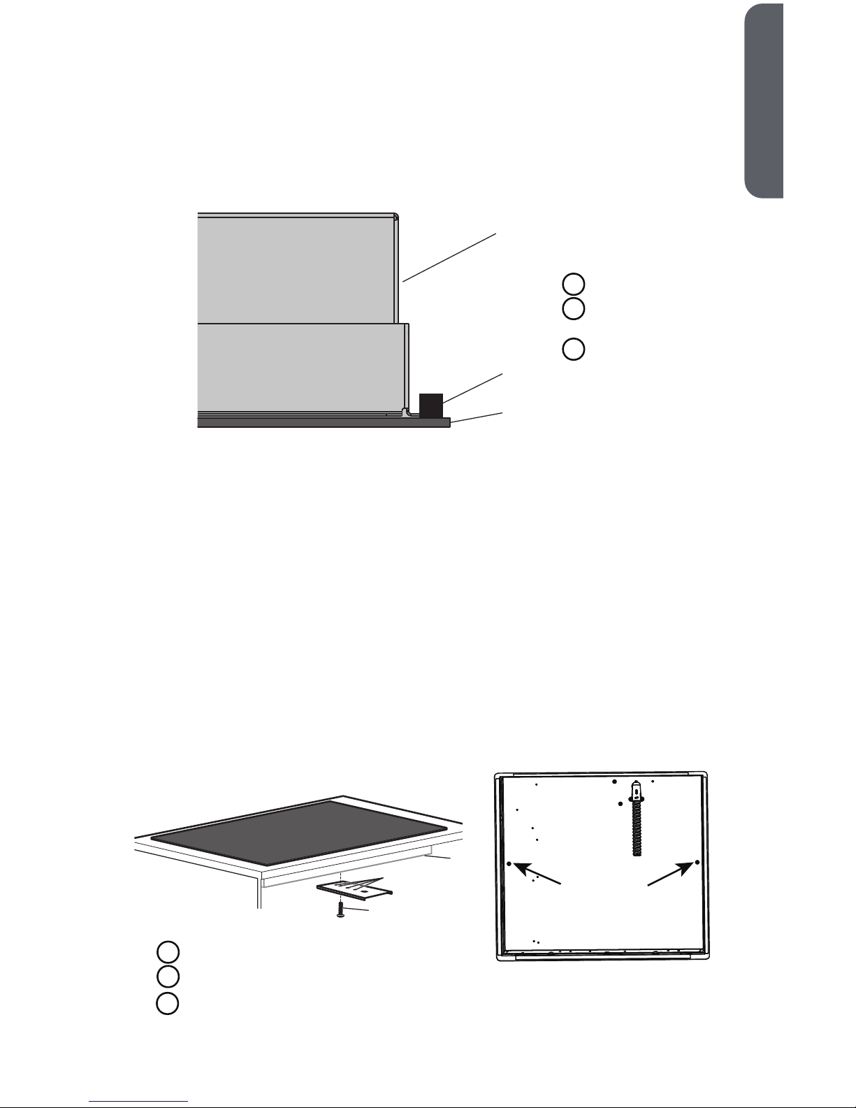
Haier HCC2220BEB User manual

Installation Instructions
Instructions d’installation
Instrucciones de instalación
HCC2220BEB
24" Electric Radiant Cooktop
Table de cuisson électrique radiante de 24"
Supercie de cocción eléctrica radiante de
24"
IMPORTANT: Save for local electrical inspector’s use.
IMPORTANT: Conserver pour consultation par l’inspecteur local des installations électriques.
IMPORTANTE: Guárdelo para uso del inspector eléctrico local.
Part # 0060522885 Rev A


TABLE OF CONTENTS
COOKTOP SAFETY .............................................................................. 2
INSTALLATION REQUIREMENTS ............................................................. 2
Tools and Parts ............................................................................. 2
Location Requirements ................................................................... 3
Electrical Requirements .................................................................. 5
INSTALLATION INSTRUCTIONS ............................................................. 6
Step 1 - Unpack Cooktop ................................................................. 6
Step 2 - Prepare for Installation ......................................................... 6
Step 3 - Install Cooktop ................................................................... 7
Step 4 - Make Direct Wire Electrical Connection .................................... 8
Step 5 - Complete Installation ........................................................ 11
1
ENGLISH

Read all safety instructions before using the product. Failure to follow these
instructions may result in fire, electrical shock, serious injury or death.

PARTS NEEDED
•UL Listed Strain Relief
•UL Listed Wire Connectors
Check local codes. Check existing electrical supply. See the appropriate “Electrical
Requirements” section. It is recommended that all electrical connections be made
by a licensed, electrical installer.
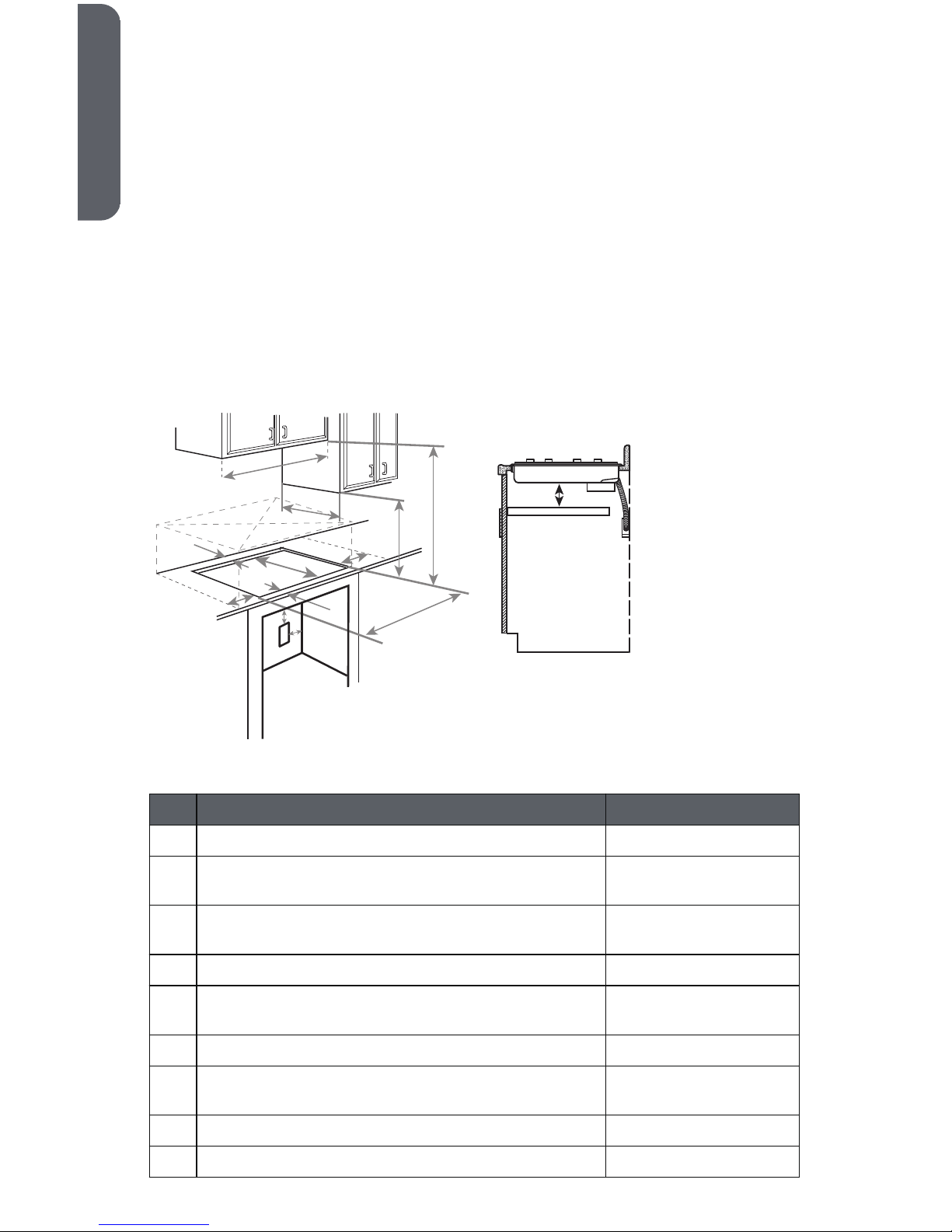
LOCATION REQUIREMENTS
IMPORTANT: Observe all governing codes and ordinances. When installing
cooktop, use minimum dimensions given.
•To eliminate the risk of burns or by reaching over heated surface units,
cabinet storage space located above the surface units should be avoided. If
cabinet storage is to be provided, the risk can be reduced by installing a range
hood or microwave hood combination that projects horizontally a minimum of 5"
(12.7 cm) beyond the bottom of the cabinets.
•The cooktop must be a cooktop that is approved to be installed either
alone or over an undercounter built-in oven.
•Ovens approved for this type of installation will have an approval label located on
the top of the oven. If you do not this label, contact your dealer to
that your oven is approved. Refer to oven manufacturer’s Installation Instructions
for approval for built-in, undercounter use and required cutout dimensions.
•The cooktop must be installed in a level countertop.
•The cooktop should be installed away from strong draft areas, such as windows,
doors, fans or strong heating vents. The cooktop should be located for
convenient use in the kitchen.
•Use the countertop opening dimensions that are given with these Installation
Instructions. Given dimensions are minimum clearances and provide 0" (0 cm)
clearance.
•Grounded electrical supply is required. See “Electrical Requirements” section.
IMPORTANT: To avoid damage, check with your builder or cabinet supplier to make
sure that the materials used will not discolor, delaminate or sustain other damage.
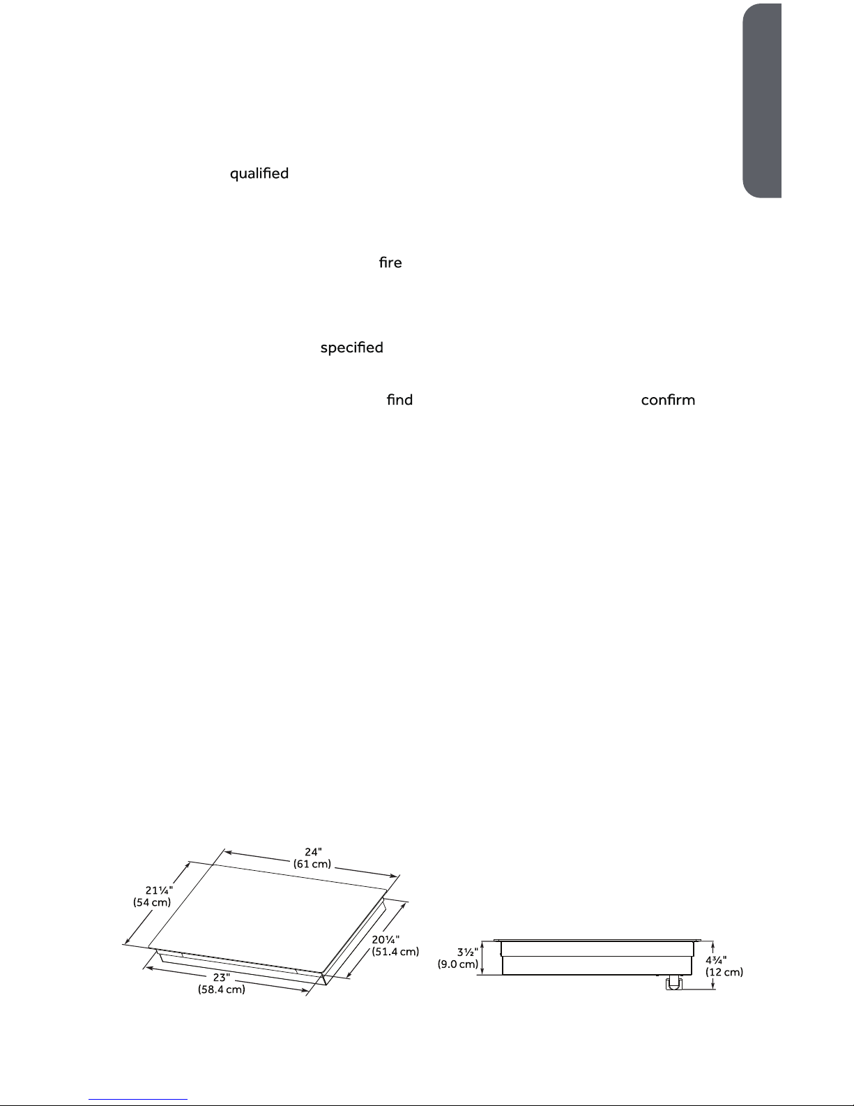
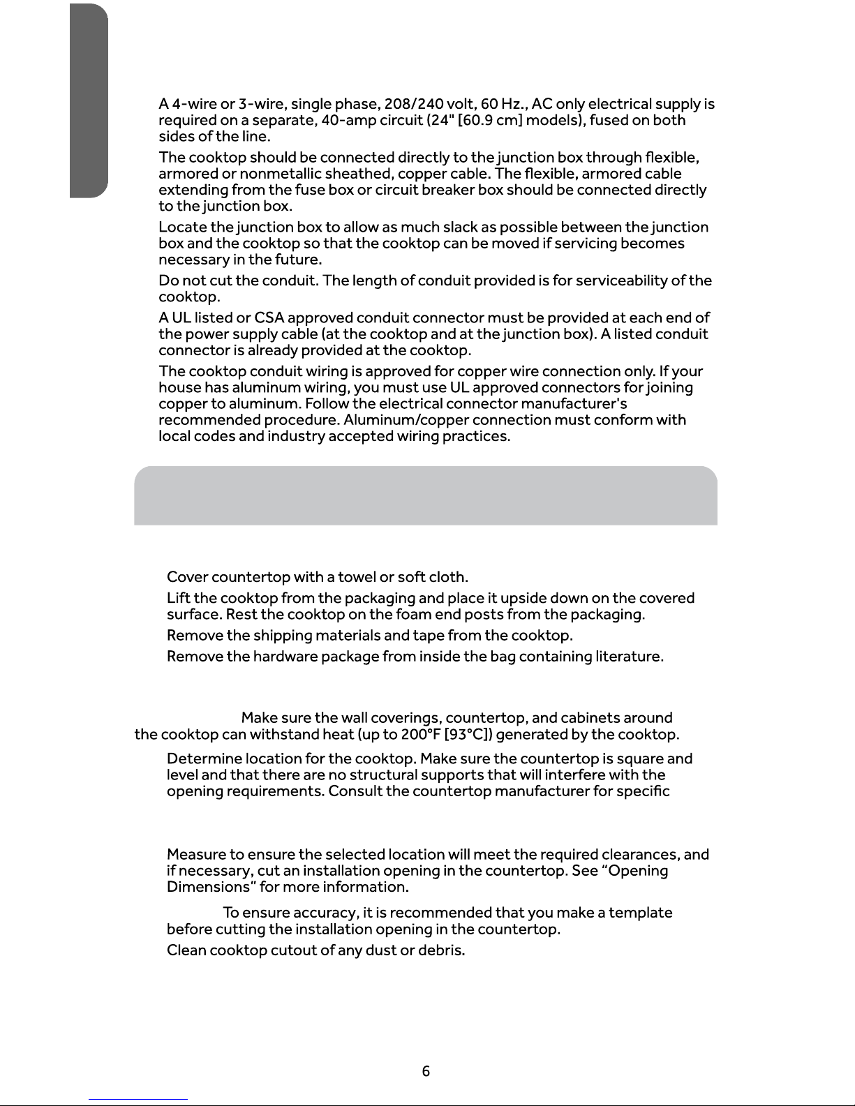
PRODUCT DIMENSIONS
3
ENGLISH
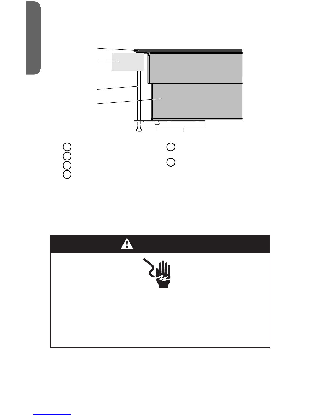
• For Personal Safety, remove house fuse or open circuit breaker before beginning
installation. Failure to do so could result in serious injury or death.
• Be sure your cooktop is installed properly by a qualified installer or service technician.
• Make sure the cabinets and wall coverings around the cooktop can withstand the
temperatures (up to 200°F) generated y the cooktop.
Always disconnect the electrical service to the cooktop before repairing or servicing the
cooktop. This can be doe by disconnecting the fuse or circuit breaker. Failure to do this
could result in a dangerous or fatal shock. Know where your main disconnect switch is
located. If you do not know, have your electrician show you.

OPENING DIMENSIONS
This cooktop has been designed to accommodate a wide range of cutout sizes to
allow possible replacement with other brands. For a new installation, we recommend
that you consider the minimum dimension of cutout size.
NOTE:
•If installing a range hood or microwave hood combination above the
cooktop, follow the range hood or combination microwave hood installation
instructions for the required clearance above the cooktop surface.
•When installing the cooktop over a base cabinet, use a base cabinet with
sidewalls wider than the cutout requirements to avoid needing to notch
down the base cabinet sidewalls to clear the cooktop base.
•If the base cabinet has a drawer, a 5¹⁄₂" (14.0 cm) depth clearance from the
top of the countertop to the top of the drawer (or other obstruction) in the
base cabinet is required.
Description Dimension
(A) Width of the cooktop 24" (60.9 cm)
(B) Combustible area above countertop 19¹⁄₄" (49.0 cm) 19¹⁄₂"
(49.7 cm)
(C) Minimum clearance between top of cooktop and
bottom of uncovered wood or metal cabinet.
30" (76.2 cm)a
(D) Recommended overhead cabinet depth 18" (45.7 cm) min
(E) Minimum clearance between front edge of
countertop and front edge of cooktop
2" (5.1 cm)
(F) Depth of cooktop opening 20⁵⁄₁₆" (51.7 cm)
(G) Min. height from countertop to nearest cabinet on
either side of the cooktop
15" (38 cm)
(H) Junction box: minimum from top of countertop 7" (17.8 cm)
(I) Junction box: maximum from right side of cabinet 9" (23.0 cm)
4
ENGLISH
”
5"

2" (5.08 cm)

ELECTRICAL CONNECTION REQUIREMENTS
•
•
•
•
•
•
INSTALLATION INSTRUCTIONS
STEP 1 - UNPACK COOKTOP
1.
2.
3.
4.
STEP 2 - PREPARE FOR INSTALLATION
IMPORTANT:
1.
instructions.
NOTE:
2.
NOTE:
3.
ENGLISH
Countertop should be 3/4" (2.0cm) to 3" (7.6cm) thick

STEP 3 - INSTALL COOKTOP
1. With the adhesive side down, apply the foam tape (provided) around the
underside of the entire cooktop. Place the foam tape so that it is approximately
¹⁄₁₆" (0.16 cm) in from the edge of the cooktop.
NOTE: The foam tape cushions the underside of the cooktop glass to help
the cooktop rest level on uneven countertops.
a
b
c
ACooktop Base
BFoam Tape
(provided)
CCooktop
2. Turn the cooktop right side up and insert the cooktop base into the cutout
opening.
NOTE:
•Make sure the cooktop is centered within the opening and that the
front edge of the cooktop is parallel with the front edge of the
countertop.
•If you need to reposition the cooktop, lift the entire cooktop from the
opening to avoid scratching the countertop.
3. Working from underneath the cooktop base, remove the clamping bracket
attachment screws (one on each side) from the bottom of the cooktop base.
4. Determine which mounting holes in the clamping brackets will allow the bracket
to extend out far enough from the cooktop base to accommodate the
installation of clamping screws.
5. Using the bracket attachment screws removed earlier, insert a screw through
the selected bracket mounting hole, and fasten the clamping bracket to the
cooktop base. Repeat for the other side of the cooktop, and then completely
tighten both attachment screws.
a
c
b
ACooktop Base
BBracket Mounting Hole
CBracket Attachment Screw
7
ENGLISH

6. Insert the long clamping screw (provided) into the outermost hole of the
clamping bracket. Repeat for the other side of the cooktop.
b
a
c
d
e f
AGlass Cooktop
BCountertop
CClamping Screw
DCooktop Base
EClamping Bracket Attachment
Screw
FClamping Bracket (extends from
the cooktop base to underneath
the countertop)
7. Using a screwdriver, tighten the clamping screws against the countertop. Do
not overtighten the screws.
STEP 4 - MAKE DIRECT WIRE ELECTRICAL
CONNECTION
To properly install your cooktop, complete electrical connections according to local
codes and ordinances.
WARNING
Electrical Shock Hazard
Disconnect power before servicing.
Use 8 gauge copper wire.
Electrically ground cooktop.
Failure to do so can result in death, fire or electrical shock.
Be sure your appliance is properly installed and grounded by a qualied
technician. Ask your dealer to recommend a qualied technician or an authorized
repair service.
This appliance is manufactured with a green GROUND wire connected to the
cooktop chassis. After making sure that the power has been turned o, connect the
exible conduit from the cooktop to the junction box using a UL listed conduit
connector.
8
ENGLISH

The Grounded Neutral and Ungrounded Neutral Graphics on the following pages and
the instructions provided, present the most common way of connecting the
cooktop. Your local codes and ordinances, of course, take precedence over these
instructions.
3-WIRE CONNECTION (GROUNDED NEUTRAL) - U.S.A. ONLY
WARNING
Electrical Shock Hazard
Grounding through the neutral conductor is prohibited for new
branch-circuit installations (1996 NEC); mobile homes; and recreational
vehicles, or in an area where local codes prohibit grounding through the
neutral conductor. For installations where grounding through the
neutral conductor is prohibited, see the Ungrounded Neutral graphic.
Use grounding terminal or lead to ground unit.
Connect neutral terminal or lead to branch circuit neutral in usual
manner.
Failure to do so could result in death, fire or electric shock.
3-Wire Cable from Home Power Supply
IMPORTANT: Use the 3-wire cable from home power supply where local
codes permit a 3-wire connection.
1. Disconnect power.
9
ENGLISH

Grounded Neutral
a
b
c
d
g
h
f
e
i
AJunction Box (not provided)
BBlack Wires
CNeutral (White) Wire
DGround (Green or Bare) Wire
ECable from Cooktop
FUL Listed Conduit Connector
GRed Wires
HUL Listed Wire Connector
IHouse Electrical Supply
2. Attach the UL listed conduit connector (F) to the junction box (not provided).
3. Thread the cable from the cooktop (E) through the conduit connector to access
the wires, and then tighten the conduit connector screw.
4. Connect the 2 black wires (B) together using a UL listed wire connector.
5. Connect the neutral (white) wire (C) from the house electrical supply to the
ground (green or bare) wire (D) from the cooktop cable using a UL listed wire
connector.
6. Connect the 2 red wires (G) together using a UL listed wire connector (H).
7. Gently tuck the wire connections into the junction box, and install the junction
box cover.
4-WIRE CONNECTION (UNGROUNDED NEUTRAL) - U.S.A. ONLY
4-Wire Cable from Home Power Supply
IMPORTANT: Use the 4-wire cable from home power supply in the U.S. where
local codes do not allow grounding through neutral, new branch circuit
installations (1996 NEC), mobile homes and recreational vehicles, new
construction and in Canada.
1. Disconnect power.
10
ENGLISH

Ungrounded Neutral
i
b
c
d
g
f
e
h
a
AJunction Box (not provided)
BBlack Wires
CRed Wires
DCable from Cooktop
EUL Listed or CSA Approved
Conduit Connector
FGround (Green or Bare) Wire
GUL Listed Wire Connector
HNeutral (White) Wire
IHouse Electrical Supply
2. Attach the UL listed conduit connector (E), to the junction box (not provided).
3. Thread the cable from the cooktop (D) through the conduit connector to
access the wires, and then tighten the conduit connector screw.
4. Connect the 2 black wires (B) together using a UL listed wire connector.
5. Connect the 2 red wires (C) together using a UL listed wire connector.
6. Connect the 2 ground (green or bare) wires (F) together using a UL listed wire
connector (G).
7. Attach a UL listed wire connector to the neutral (white) wire (H) from the house
electrical supply.
8. Gently tuck the wire connections into the junction box, and install the junction
box cover.
STEP 5 - COMPLETE INSTALLATION
1. Clean cooktop before use with a solution of mild detergent and warm water.
Dry thoroughly with a soft cloth. For more information, see “Cooktop Care” in
the User Manual.
2. Reconnect power at the circuit breaker or fuse box.
3. Turn on each element to check that it is heating correctly.
4. Check that the indicator lights on the control panel, and the interior oven lights
illuminate correctly.
If the cooktop does not operate correctly, check the following:
•Household fuse is intact and tight; or circuit breaker has not tripped.
•Cooktop is plugged into a grounded outlet.
•Electrical supply is connected.
Contact a qualied electrician to verify the electrical supply.
11
ENGLISH

TABLE DES MATIÈRES
SÉCURITÉ DE LA TABLE DE CUISSON ..................................................... 13
EXIGENCES D'INSTALLATION ............................................................... 13
Outils et pièces ........................................................................... 13
Exigences d’emplacement ............................................................. 14
Spécications électriques .............................................................. 17
INSTRUCTIONS D'INSTALLATION .......................................................... 18
Étape 1 - Déballage de la table de cuisson .......................................... 18
Étape 2 - Préparation pour installation .............................................. 18
Étape 3 - Installation de la table de cuisson ......................................... 19
Étape 4 - Raccordement électrique direct .......................................... 20
Étape 5 - Fin de l’installation ........................................................... 24
12
FRANÇAIS

Lisez toutes les consignes de sécurité avant d'utiliser le produit. Le non-respect
de ces recommandations comporte un risque de d'électrocution et de blessures
graves, voire mortelles.

PIÈCES FOURNIES
••
•
PIÈCES NÉCESSAIRES
•
•
EXIGENCES D’EMPLACEMENT
IMPORTANT :
•
•
travail.
•
•
•
•
•
IMPORTANT :
FRANÇAIS
• Pour votre propre sécurité, pensez à déconnecter le fusible ou le disjoncteur
avant d’entreprendre l’installation. Ne pas respectez ces consignes peut mener à
de graves blessures, voire la mort.
• Assurez-vous que votre table de cuisson soit installée conformément par un
installateur qualifié ou par un technicien compétent.
• Assurez-vous que les placards et les revêtements muraux présents à proximité
de la table de cuisson peuvent supporter des hautes températures (jusqu’à 93°
C) générées par la table de cuisson.
• Veillez à toujours couper l’électricité alimentant la table de cuisson avant
d’entreprendre toute réparation ou tout entretien. Cela peut se faire en décon-
nectant le fusible ou le disjoncteur Ne pas respectez ces consignes peut mener à
de graves blessures, voire la mort. Assurez-vous de connaître l’emplacement de
votre coupe-circuit principal. Si vous n’avez pas connaissance de ce dernier,
demandez à votre électricien de vous montrer.

DIMENSIONS DU PRODUIT
DIMENSIONS DE L’OUVERTURE
REMARQUE :
•
•
•
FRANÇAIS

Description Dimension
(A) Largeur de la table de cuisson 24" (60,9 cm)
(B) Zone de matière combustible au-dessus du plan
de travail
19¹⁄₄" (49,0 cm) 19¹⁄₂"
(49,7 cm)
(C) Dégagement minimum entre le dessus de la table
de cuisson et le fond du placard de bois ou de
métal non protégé
30" (76,2 cm)a
(D) Profondeur recommandée du placard du haut 18" (45,7 cm) min
(E) Dégagement minimum entre le bord avant du plan
de travail et le bord avant de la table de cuisson
2" (5,1 cm)
(F) Profondeur de la découpe de la table de cuisson 20⁵⁄₁₆" (51,7 cm)
(G) Hauteur minimum entre le plan de travail et le
placard le plus proche, à partir de n'importe quel
côté de la table de cuisson
15" (38 cm)
(H) Boîte de jonction : minimum à partir du dessus du
plan de travail
7" (17,8 cm)
(I) Boîte de jonction : maximum à partir de la droite
du placard
9" (23,0 cm)
(J) Largeur de la découpe de la table de cuisson 23" (58,7 cm)
(K) Dégagement minimum du bord de l'ouverture à la
paroi latérale la plus proche
2" (5,08 cm)
2" (5,08 cm)(L) Distance minimale entre le mur arrière et table de
cuisson
aDégagement minimum de 24 po (61 cm) lorsque le fond d’un placard de bois ou de métal est protégé
par une planche ignifugée d’au moins ¼ po (0,6 cm) recouverte d’une tôle d'acier d’épaisseur égale ou
supérieure au calibre 28 MSG, d'acier inoxydable de 0,015 po (0,04 cm), d'aluminium de 0,024 po
(0,06 cm), ou de cuivre de 0,020 po (0,05 cm).
16
FRANÇAIS
DÉGAGEMENT
VERTICAL
5"
Allow 5” minimum
vertical clearance
from the cooktop-
bottom minimum
depthfrom to any
combustible
surfaces, such as a
cabinet drawer.

SPÉCIFICATIONS ÉLECTRIQUES
Risque de choc électrique
Déconnecter la source de courant électrique avant l’intervention.
Utiliser des conducteurs en cuivre de calibre 8 ou en aluminium de
calibre 6.
Relier la table de cuisson à la terre.
Le non-respect de cette instruction peut causer un décès, un incendie
ou un choc électrique.
AVERTISSEMENT
Si les codes locaux le permettent et un l de terre séparé est utilisé, il est
recommandé qu’un électricien qualié vérie que le chemin de terre est adéquat et
que le calibre du l de terre est conforme aux codes locaux.
En cas de doute, vérier la qualité de la liaison à la terre de la table de cuisson avec
un électricien qualié.
Ne pas utiliser de rallonge.
Aux États-Unis :
S’assurer que la connexion électrique et le calibre des ls sont appropriés et en
conformité avec le National Electrical Code, ANSI / NFPA n° 70 - dernière édition et
avec tous les codes et règlements locaux.
On peut obtenir un exemplaire de la norme ci-dessus auprès de :
National Fire Protection Association
One Batterymarch Park
Quincy, MA 02269
Au Canada :
Vérier que le raccordement à la source d’électricité et le calibre des conducteurs
sont conformes aux prescriptions de la plus récente édition de la norme CSA C22.1,
partie 1 - Code canadien de l’électricité, et de tout code ou règlement local en
vigueur.
On peut obtenir un exemplaire de la norme ci-dessus auprès de :
Canadian Standards Association
178 Rexdale Blvd.
Toronto, ON M9W 1R3 CANADA
CONNEXION ÉLECTRIQUE
•L'appareil doit être alimenté uniquement par un circuit monophasé de 208/240 V
CA, 60 Hz à 4 ls ou 3 ls, sur un circuit séparé de 40 ampères (modèles de 24 po
[60,9 cm]), protégé par fusible aux deux extrémités de la ligne.
17
FRANÇAIS

•
•
•
•
•
INSTRUCTIONS D'INSTALLATION
ÉTAPE 1 - DÉBALLAGE DE LA TABLE DE CUISSON
1.
2.
3.
4.
ÉTAPE 2 - PRÉPARATION POUR INSTALLATION
IMPORTANT :
1.
REMARQUE :
2.
renseignements.
REMARQUE :
3.
FRANÇAIS
Le comptoir devrait être d’une épaisseur comprise
entre 3/4" (2.0cm) et 3" (7.6cm).
Other manuals for HCC2220BEB
2
Table of contents
Languages:
Other Haier Cooktop manuals

Haier
Haier HCE905TB3 User manual

Haier
Haier HCI604TG3 User manual

Haier
Haier HCE604TB Mounting instructions

Haier
Haier HCC2220BEB User manual

Haier
Haier HCE604P Mounting instructions

Haier
Haier HAIH8IFMCE User manual

Haier
Haier HCG604WFCG3 User manual

Haier
Haier HCC2230AGS User manual

Haier
Haier HCC2230AGS User manual

Haier
Haier HCI604TPB3 User manual

Haier
Haier HCE604TB3 User manual

Haier
Haier HCE604TB3 User manual

Haier
Haier HGRA201AAWW User manual

Haier
Haier HCG905WFCG3 User manual

Haier
Haier HCC2220BEB User manual

Haier
Haier HCC2320AES User manual

Haier
Haier HCC2430AGS User manual

Haier
Haier HCC2320AES User manual

Haier
Haier HCG604W Mounting instructions