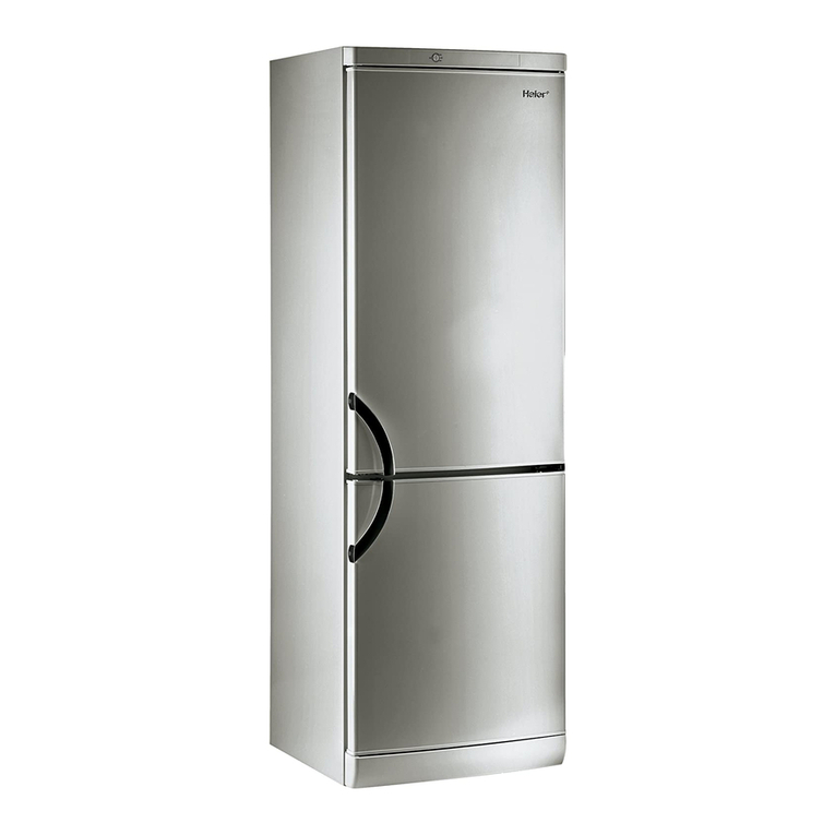
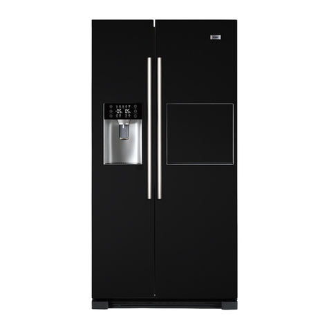
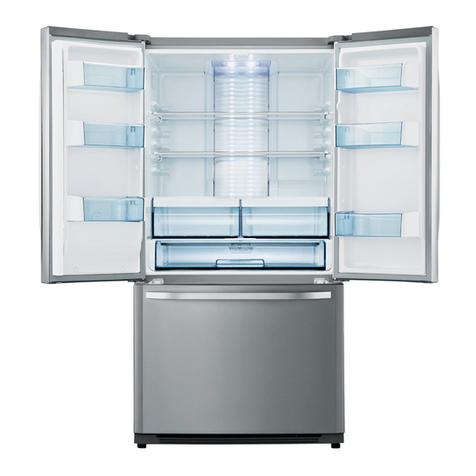
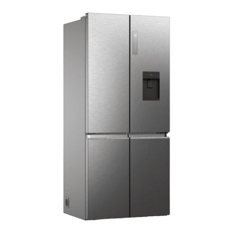
Haier HRF-663ISB2 Series User manual

Order No.Ref1001S015V0
200Ƽ9(HAIER ELECTRICAL APPLIANCES COR. LTD)
Allrightreserved.UnauthorizedcopyinganddistributionisaviolationoflawDŽ
Refrigerator
SERVICE MANUAL
MODEL: HRF-663ISB2
Haier Group
This service information is designed for experienced repair technicians only and is not designed for use by the general public. It
dose not contain warnings and cautions to advice non-technical individuals of potential dangers in attempting to service a product.
Product powered by electricity should by serviced or repaired only by experienced professional technicians. Any attempt to service
or repair the product or products dealt with in this service information by anyone else could result in serious injury or death.
WARNING

SERVICE MANUAL
Model: HRF-663ISB2
2
Issue 2010-01
Rev. Ref1001S015V0
Contents
Table of Contents ·········································································································· 2
1. General Information·································································································· 4
1-1. General guideline ······························································································· 4
1-2. Important notice·································································································· 4
1-3. How to read this Service Manual········································································ 5
2. Product Feature ········································································································ 6
2-1. Specifications ····································································································· 6
2-2. External views ···································································································· 8
3. Installation, adjustments and maintenance····················································· 9
3-1. Door ··················································································································· 9
3-2. Handle················································································································ 9
3-3. Down decorative moulding················································································· 10
3-4. Adjustable foot···································································································· 10
4. Disassembly·············································································································· 11
4-1. Switch················································································································· 11
4-2. Air passage cover assembly in Fridge room ······················································ 11
4-3. Air passage cover assembly in Freezer room ···················································· 12
4-4. Control panel box and display panel ·································································· 13
4-5. Display panel······································································································ 13
4-6. Ice crushed motor······························································································· 13
5. Control principle and display system ····································································· 14
5-1. Control and display panel··················································································· 14
5-2. Function adjustment and work principle ····························································· 14
6. System flow principle······························································································· 22
6-1. Refrigeration flow scenograph ·········································································· 22
6-2. Water flow scenograph ····················································································· 23
7. Circuit diagram·········································································································· 24
7-1. Brief principle diagram ······················································································ 24
SERVICE MANUAL
Model: HRF-663ISB2
3
Issue 2010-01
Rev. Ref1001S015V0
7-2. Main control PCB diagram················································································ 25
8. Trouble shooting······································································································· 26
8-1. Normal phenomena ·························································································· 26
8-2. Common Troubles in Refrigerators and Their Remedies······································ 27
8-3. Analysis of Troubles and Troubleshooting··························································· 29
8-3-1.
Poor Refrigerating Effect ········································································ 29
8-3-2. No Refrigerating ···················································································· 32
8-3-3.
Sudden stops························································································· 34
8-3-4. Compressor could not be start································································ 36
8-3-5. Problem with ice making······································································· 37
8-3-6.
Electric leakage of refrigerator································································ 38
8-3-7. Stronger vibration and loader noise ························································ 39

SERVICE MANUAL
Model: HRF-663ISB2
4
Issue 2010-01
Rev. Ref1001S015V0
Chapter 1 General Information
1-1. General Guidelines
When servicing, observe the original lead dress. If a short circuit is found, replace all parts which
have been overheated or damaged by the short circuit. After servicing, see to it that all the protective
devices such as insulation barriers, insulation papers shields are properly installed. After servicing,
make the following leakage current checks to prevent the customer from being exposed to shock
hazards.
1) Leakage Current Cold Check
2) Leakage Current Hot Check
3) Prevention of Electro Static Discharge (ESD) to Electrostatic Sensitive
1-2. Insurance notice
1. Check if there is any leak of current.
2. Cut out the power supply before the repair to avoid an electrical shock hazard.
3. In the case of a live-line test, insulating gloves should be worn to avoid potential electrical shock.
4. Confirm the rated current, voltage and capacity before testing with any kinds of instruments.
5. Watch if the upper door is open when you check something at a lower position.
6. Take out every part in the cabinet before moving the machine, especially things like panels (e.g. glass
shelf).
7. Please wear intact cotton gloves when repair any parts of the evaporator, so that scratches by the
sharp fins can be avoided.
8. If there is a breakdown with the refrigeration system, please surrender the machine to the service
center, else the leaked refrigerant may pollute the atmosphere.
9. The refrigerator use AC of 220V with a frequency of 50Hz.
10. A big fluctuation of voltage (exceed the range 187242V) may cause a start failure of the refrigerator,
a burn-out of the control panel and compressor, or an abnormal sound from the compressor in
operation. In this condition an automatic voltage regulator over 200W should be added.
11. Take care not to damage the supply line. Don’t yank at the line; pull the plug out gently from the
receptacle. Don’t press the line under the cabinet or step on it. Take care not to roll on or damage the

SERVICE MANUAL
Model: HRF-663ISB2
5
Issue 2010-01
Rev. Ref1001S015V0
supply line when moves the machine from the wall.
12. In the case of leakage of inflammable gases like carbon monoxide, open the door and windows. Don’t
pull out or insert the plugs of the appliance.
13. Don’t touch the refrigeration surface of the freezing compartment when the refrigerator is in operation,
especially when your hand is wet, else you may be glued to the surface.
14. Pull out the plug of power supply during clearance or power outage. Wait at least five minutes to
resume the power supply in order to prevent damage to the compressor caused by continuous restart.
Photo used in this manual
The illustration and photos used in this Manual may not base on the final design of products, which
may differ from your products in some way.
1-3. How to read this Service Manual
1-3-1. Using Icons
The meaning of each icon is described in the table below:
Note:
A “note” provides information that is not indispensable.
Caution:
A “caution” is used when there is danger, through incorrect manipulation, may damage equipment,
loose data, get an unexpected result or has to restart (part of) a procedure.
Warning:
A “warning” is used when there is danger of personal injury.
Reference:
A “reference” guides to other places in this binder or in this manual, where we will find additional
information on a specific topic.

SERVICE MANUAL
Model: HRF-663ISB2
6
Issue 2010-01
Rev. Ref1001S015V0
Chapter 2 Product Feature
2-1. SPECIFICATIONS
REFRIGERATOR
1Model units HRF-663ISB2
Commercial brand
Haier
Product description SBS
Type of Appliance (FS= freestanding BI= built-in) FS
Climate class (N= + 18-32 °C T=+ 18-43 °C) SN.N.ST
2Key features
Gross capacity l519
Total net capacity l499
Defrosting (H=manual A=automatic) Fridge/Freezer A
Defrost water outlet Yes
Air circulating ventilator Yes
Kindofcoolant (R134a/R600a) R600a
Foaming components CP-IP
3Technical data
Voltage / frequency V/Hz 220-240 V~/ 50
Input power / mains fuse minimum W /A 200/2.2
Length of cable / incl. plug cm 200
Temperature range (from>to) Fridge / Freeze °C 10~-26
4Aesthetics
Colours (see L):Silver
Top cover Silver
Cabinet Silver PCM
Door Silver VCM
Fascia panel / Handle Silver
Door:
F= Flat / R= Rounded / S= Streamline F
Hinged (r =right l =left) / reversible) r & l
Lock (yes/not) No

SERVICE MANUAL
Model: HRF-663ISB2
7
Issue 2010-01
Rev. Ref1001S015V0
Shelves:
Number
8
Type (gr=grill/g=glass/p=plastic)
glass:8
Colour of shelves
white
Adjustable
YES
Drawers:
Number n°. 4
Crisper:
Salad crisper(s) transparent / white transparent
5Equipment & Accessories
Control Panel:
Controlpanel interior / exterior Exterior
Controllamps green / yellow / red blue
Over temperature ALARM LED / acoustic acoustic
Adjustable thermostat Yes
Fast freeze switch Yes
Interior light W 2
Adjustablefeet front / rear n° front
Castors front/rear front / rear
6Product dimensions
Unitdimensions H / W / D cm 176.8*89*77
Depth with open door cm 110
Net weight kg 120
7Packing dimensions & load ability
Packingdimensions H / W / D cm 189.4*96*77
Gross weight kg 128
8Recycling symbols
Carton weight in g kg 8
9Service
Users instruction (languages) English

SERVICE MANUAL
Model: HRF-663ISB2
8
Issue 2010-01
Rev. Ref1001S015V0
2-2. External views
There is no home bar baffle for this model.

SERVICE MANUAL
Model: HRF-663ISB2
9
Issue 2010-01
Rev. Ref1001S015V0
Chapter 3 Installation, adjustments and maintenance
3-1. Door
1. Loosen the screw by screwdriver, and then remove the hinge cover from upper way.
2. Loosen the screw fixing the upper hinge to the body and lift the door.
3. Pull out the door gasket from the door assembly.
3-2. Handle
1. Door gasket can be pulled out from door foam assembly.
2. Fix the bolt into the hole on the door, and then use the handle aiming to the bolt, push the handle down
until it touch the door firmly.
Part 1
Part 2
Part 3

SERVICE MANUAL
Model: HRF-663ISB2
10
Issue 2010-01
Rev. Ref1001S015V0
3-3. Below decorative moulding
Open the refrigerator and freezer doors, remove the moulding from the refrigerator compartment, and
then affix it as shown in the illustration.
3-4. Adjustable foot
If the freezer compartment door is lower than that of the refrigerator compartment, insert the wrench
in the groove of the left screw and turn it in the direction of the arrow until both doors are the same
height.
If the freezer compartment door is lower than that of the refrigerator compartment, insert the wrench
in the groove of the left screw and turn it in the direction of the arrow until both doors are the same
height.

SERVICE MANUAL
Model: HRF-663ISB2
11
Issue 2010-01
Rev. Ref1001S015V0
Chapter 4 Disassembly
4-1. Switch
1. To remove the switch pulls out it with a “_”type screwdriver as
shown in.
2. Disconnect the lead wire from switch.
4-2 Air passage cover assembly in Fridge room.
1. Unplug the power cord from the outlet;
2. Remove the fridge shelf;
3. Remove the lamp cover (see pic 1);
4. The bulb can be replaced;
5. Loosening 2 screws fixed to ceiling of inner liner;
6. Pull out the electric damper; wind passage and the wind passage cover (see pic 2);
7. After replaced the disabled parts, assemble in reverse order of disassembly.
Pic1 Pic2

SERVICE MANUAL
Model: HRF-663ISB2
12
Issue 2010-01
Rev. Ref1001S015V0
4-3. Air passage covers assembly in Freezer room
1. Unplug the power cord from the outlet;
2. Remove the freezer shelf;
3. Remove the lamp cover (see pic 1); the bulb can be replaced;
4. Loosening 2 screws fixed the cover and pull out the top freezer air tower (see pic 2);
6. Pull out the bottom freezer air tower and unplug the sensor cable (see pic3);
7. Pull out the freezer fan motor rack, unplug the fan motor cable and separate the fan motor , fan
motor cover and the rack (see pic4 and 5);
8. Pull out the freezer air shutter (see pic6);
9. Unplug the defrost sensor cable (see pic7);
10. Assemble in reverse order of disassembly.
Pic1 Pic2 Pic3 Pic4
Pic5
Pic6 Pic7

SERVICE MANUAL
Model: HRF-663ISB2
13
Issue 2010-01
Rev. Ref1001S015V0
4-4. Control panel box and control panel
1. Unplug the power cord from the outlet;
2. Loosening 4 screws fixed the control panel box cover;
3. Open the cover;
4. Replace the filter panel and control panel.
4-5. Display panel
1. Unplug the power cord from the outlet;
2. Loosening 2 screws fixed the bottom of control panel
assembly;
3. Unplug the display panel;
4. Loosening 4 screws fixed the control panel.
4-6. Ice crushed motor
1. Unplug the power cord from the outlet;
2. Pull out the ice-crushed box and loosening the screws from the ice-crushed box slide way;
3. Pull out the ice-crushed box slide way;
4. Take out the ice box and then take out the ice box motor;
5. Loosening 4 screws from the ice maker support and put it out;
6. Loosening 2 screws from the ice-crushed motor box and put it out;
7. Disconnected the ice-crushed motor box cable.

SERVICE MANUAL
Model: HRF-663ISB2
14
Issue 2010-01
Rev. Ref1001S015V0
Chapter 5 Control principle and display system
5-1. Control panel
1. Keys and Display panel
The screen becomes dark automatically 30 minutes after key operation. Press any key or open any
door to restore the display.
A. Intelligent mode key E. Intelligent mode indicator
B. Super frost key F. Super frost indicator
C. Freezer temperature adjustment key G. Freezer temperature display
D. Refrigerator temperature adjustment key H. Refrigerator temperature display
5-2. Function adjustment and working principle
1. Initial State
1.1 For initial power-on, the temperature setting for refrigerator compartment and freezer compartment is
preset at fuzzy mode; fast freeze is not selected.
1.2 For initial power-on, if the temperature of refrigerator compartment falls within the range of
temperature corresponding to starts and stops of compressor, the compressor won’t start until the
temperature rises to the starting point; if the temperature of freezer compartment is higher than the
shutdown point, the compressor is started.
1.3 After the first power-on, the previous state will be displayed when the unit is powered on again.
2. Temperature setting of freezer compartment / refrigerator compartment
FUZZY Quick. FRZ FRZ. Temp REF. Temp

SERVICE MANUAL
Model: HRF-663ISB2
15
Issue 2010-01
Rev. Ref1001S015V0
Temperature Parameters
Refrigerator
setting
Refrigerator sensor 2 Freezer
setting
Freezer sensor
ON OFF ON OFF
+7
ć
+7.5ć+4.5ć-15ć-15.5ć-18.5ć
+6
ć
+6.5ć+3.5ć-17ć-17.5ć-20.5ć
+5
ć
+5.5ć+2.5ć-18ć-18.5ć-21.5ć
+4
ć
+3.5ć+0.5ć-20ć-20.5ć-23.5ć
+3
ć
+1.5ć-1.5ć-22ć-22.5ć-25.5ć
2.1 How to select a temperature setting
(1)The appliance is preset at fuzzy mode, which can be inactivated by a press of Fuzzy Mode button.
(2)The temperature setting of freezer compartment / refrigerator compartment are set by the freezing and
refrigeration keys on the display panel respectively..(Fuzzy mode must be inactivated.)
(3) The freezing/ refrigeration keys correspond with display icons.
(4) Press and hold down the refrigeration key for 3 seconds, the refrigeration operation in refrigerator
compartment is deactivated and its temperature setting display is off; press and hold down it again for 3
seconds, the refrigeration function is resumed and its temperature setting display is on. When the
refrigeration function is suspended, the refrigeration load is canceled in correspondence to 2.
2.2 Displays
(1) Press freeze or cold storage key once to obtain the next higher setting until the highest setting is
reached. Press again to return to the lowest setting.
(2) Room Temperature Sensor (RT SNR) The startup and shutdown parameters can be adjusted with the
temperature change of RT SNR.
RT20°C 20°C<RT35°C 35°C<RT
Freeze -2°C -1°C -2°C
Cold storage +1°C -1 -2°C
Freeze 1ĺ2ĺ3ĺ4ĺ5ĺ1 / The sequence of temperature displays is:
-15°Cĺ-17°Cĺ-18°Cĺ-20°Cĺ-22°Cĺ-15°C
Cold storage 1ĺ2ĺ3ĺ4ĺ5ĺ1 /The sequence of temperature displays is:
7°Cĺ6°Cĺ5°Cĺ4°Cĺ3°Cĺ7°C
Type Display

SERVICE MANUAL
Model: HRF-663ISB2
16
Issue 2010-01
Rev. Ref1001S015V0
2.3 Controls
2.3.1 Temperature Control
(1) Temperature control of freezer compartment /refrigerator compartment
(2) Name and position of each sensor
Name Code Location
Freezer sensor F SNR Side wall of freezer
Refrigerator sensor 1 R1 SNR Refrigerator damper assembly
Refrigerator sensor 2 R2 SNR Side wall of refrigerator
Ambient temperature sensor RT SNR Below hinge box of freezer
Ice maker sensor ICE SNR Below ice maker
Defrost sensor D SNR Above freezer evaporator
k
(F)
(D)
(ICE)
(5)
(5)
(57)
Freezer
compartment NOTCH+1.5°C NOTCH-1.5°C F SNR
Refrigerator
compartment NOTCH+1.5°C NOTCH-1.5°C R1 SNR
Item Compressor ON or air
damper ON
Compressor OFF or air
damper OFF Sensor

SERVICE MANUAL
Model: HRF-663ISB2
17
Issue 2010-01
Rev. Ref1001S015V0
2.3.2 Compressor Control
(1) ON/OFF conditions of compressor
(2) The compressor will be shut down during operating if one of the following appears:
a) During defrosting or within 7 minutes after the finishing of defrosting.
b) Within 7 minutes after compressor shutdown.
c) Within 7 minutes after the previous state is restored manually from forced state.
2.3.3 Freezer fan control DC fan is adopted for the control of freezer fan.
DC fan is adopted for the control of freezer fan.
(1) ON/OFF conditions of freezer fan
2.3.4 Control of cooling fan
(1)A DC fan is adopted.
(2)The fan is operating synchronously with compressor
(3)Under DC control, the fan works at a constant speed of 1100RPM (11V).
2.3.5 Lighting control of refrigerator
(1)The light is on if the door is opened; the light extinguishes if the door is closed.
(2)The light extinguishes automatically if the door is opened for more than 7 minutes.
2.3.6 Air damper control of refrigerator
(1) R1 SNR controls the startup and shutdown of air damper in refrigerator compartment.
(2) The air damper is closed (in order to prevent the compartment from freezing) within 15 minutes from
the beginning to the finishing of defrosting.
(3) The air damper is closed and opened once upon initial power-on. It is controlled opened and closed
as per condition (1).
ON OFF
1. Powered on for the first time or after defrosting (F
SNR is higher than shutdown point)
2. F SNR reaches startup point
3. In fast freeze state
4. Refrigerator load in correspondence with condition 2
5. TEST MODE1 (PULL DOWN) DŽ
1. After defrosting, F SNR is not higher than
shutdown point;
2. F SNR reaches shutdown point
3. In defrosting state;
4. Refrigerator load not in correspondence
with condition 2
5. TEST MODE2 (forced defrosting)

SERVICE MANUAL
Model: HRF-663ISB2
18
Issue 2010-01
Rev. Ref1001S015V0
(4) Force the air damper to be opened and closed once if it cannot be opened within 1 hour. After that,
decide whether open or close it according to R1 SNR.
(5)Heating elements of air damper and ice outlet are heated synchronously. continuous heating
(6) If the temperature still rises (or drops) within 10 minutes after opening or closing of air damper, open
or close it again.
(7) Heating element of dispenser (as well as heating element of inlet pipe) is off for 10 minutes and is
on for 30 minutes as a cycle.
2.4 Functional controls
2.4.1 Fast freeze
(1)Press fast freeze key to activate this function.
(2)Corresponding icon is displayed in fast freeze state; the icon extinguishes when fast freeze is
ended.
(3) During fast freeze, the selected settings of freezer or refrigerator compartment remain unchanged.
(4)During fast freeze, the setting in refrigerator compartment is adjustable, while the setting in freezer
compartment is not.
(5)The compress operates 3 hours continuously and then stops in fast freeze.
(6)Defrosting has a higher priority than fast freeze. The defrosting time is included in fast freeze time.
The fast freeze display is on all the time during defrosting. End of fast freeze and end of automatic
defrosting are controlled by respective conditions. When either of the two states is ended, the other state
will not be affected.
2.4.2; Refrigerator load in correspondence with condition 2
(1) Ambient temperature is above 18°C.
(2) If the temperature of R1 is higher than 12°C or the temperature of R1 is higher than 13°C, the
compressor starts up and the air damper of refrigerator compartment is opened. The freezer fan operates
at a speed of 1500RPM.
(3) If R1 reaches shutdown point or the temperature of R2 drops below 2°C, that the refrigerator load
corresponding with condition 2 is ended.
(4) After the end of refrigerator load corresponding with condition 2, the rotation speed of fan is
1300RPM within 10 hours whatever the actual temperature is in freezer or refrigerator compartment.

SERVICE MANUAL
Model: HRF-663ISB2
19
Issue 2010-01
Rev. Ref1001S015V0
2.5 Defrosting
2.5.1 Normal defrosting (automatic defrosting)
(1)The compressor operates 7 hours accumulatively before defrosting is activated; when defrosting
SNR reaches above 7°C, defrosting is ended.
(2)The compressor stops and air damper is closed during defrosting.
(3)The compressor operates 4 hours accumulatively upon initial power-on before the first defrosting is
activated.
(4) Automatic defrosting begins after the compressor operates accumulatively 7 hours except for (3).
(5)Defrosting will not begins if there is something wrong with defrosting SNR (short circuit or broken
circuit).
(6) If the defrosting SNR cannot reach 7°C 120 minutes after defrosting, the defrosting heating
element is disconnected and an alarm is given, which glitters in the Position 4. If the SNR can reach 7°C
within 120 minutes, the alarm is canceled.
(7) The compressor and freezer fan are operated before defrosting until the freeze SNR reaches the
shutdown point -2°C to begin defrosting, which minimize the temperature rise in freezer and refrigerator
compartments during defrosting (pre-refrigeration before defrosting).
(8) After defrosting, if the compressor operates 4 hours continuously, the defrosting will begin again.
(9)Fast freeze display is powered on in fast freeze state during defrosting while automatic defrosting goes
on. At the end of automatic defrosting, fast freeze will begin again. The remaining time of defrosting is
included in fast freeze time.
(10) After defrosting, the compressor and fan stops 7 minutes, if F SNR is higher than shutdown point,
the compress starts up 5 minutes, after that, the fan operates. The air damper will be opened or closed
according to temperature after the fan has operated for 3 minutes.
2.5.2 Forced defrosting
(1)Press TEST key twice on main control panel to start forced defrosting.
(2)With the door closed, the heating element is forced open, the defrosting will stops after 4 minutes or
defrosting SNR reaches 7°C. The temperature settings of freezer and refrigerator compartment return to
the state before forced defrosting. If F SNR is higher than the shutdown point 7 minutes after the
compressor and fan are off, the compressor will operate for 5 minutes and then the freezer fan will operate

SERVICE MANUAL
Model: HRF-663ISB2
20
Issue 2010-01
Rev. Ref1001S015V0
for 3 minutes. The air damper will be opened or closed accordingly.
2.6 Door-open alarm
(1)If the door of freezer or refrigerator compartment stays open for 60 seconds, an alarm will be given.
(2)The buzzer gives alarm 3 times every 0.5 second. If any switch is powered on, the buzzer gives 3
alarms at an interval of 0.5 seconds every 30 seconds until the two switches are disconnected. The
buzzer gives a sound of “ding dong” when alarming.
(3) Alarm stops after the door is closed
2.7 Functional tests
2.7.1 Additional information of TEST functions
(1) Continuous operation in TEST 1 MODE.
(2)TEST2 should be activated 0.1 second later from TEST1 to TEST2.
(3)The keys on display panel are inactivated in TEST1 or TEST2 MODE.
(4)It is useless to press TEST key before powered on.
(5)TEST cannot be used in fault mode. If there is fault detected in TEST, it can be displayed after the reset
of control panel.
7(67
(QWHUE\SUHVVLQJ7(67
NH\RQHWLPHFRROLQJ
FDSDFLW\02'(
&203 21))$1KLJK
VSHHG21&)$1ORZ
VSHHG21'()%$5+75
2))DLUGDPSHUVDUH
RSHQHG
:LWK7(677(67
PRGHLVPDLQWDLQHG
XQWLOPDQXDOO\HQGHG
7(67
(QWHUE\SUHVVLQJ7(67
NH\RQFHPRUHLQ7(67
02'(IRUFHGGHIURVWLQJ
02'(
&203 2)))&)$1
2))'+7521DLU
GDPSHUVDUHFORVHG
3UHVVH[LWNH\WRIRUFH
GHIURVWLQJWRRSHUDWH
1RUPDO
UHVHW
UHVHWE\3UHVVLQJ7(67
NH\IRUWKHUGWLPH
5HVHWRIUHIULJHUDWRUIXQFWLRQVWKHFRPSUHVVRUZLOOVWDUW
PLQXWHVODWHU
MODE Action Description Remark
Other manuals for HRF-663ISB2 Series
1
Table of contents
Other Haier Refrigerator manuals

Haier
Haier AFD631CX - 2 User manual

Haier
Haier HRF-663ISB2 Series User manual

Haier
Haier HRC3211AC User manual

Haier
Haier PBFS21 Series User manual

Haier
Haier HB21FSSAA User manual

Haier
Haier HT21TS45SW Assembly instructions

Haier
Haier HRF-352A

Haier
Haier HTF-540DGG7 User manual

Haier
Haier HRF-220 User manual

Haier
Haier HRF-340H User manual

Haier
Haier HRH-137 User manual

Haier
Haier HRT Series User manual

Haier
Haier HB21FC45N Series User manual

Haier
Haier JF-NUF136A User manual

Haier
Haier HSBS562IS User manual

Haier
Haier HRF10WNBLWW User manual

Haier
Haier HRF15N3 User manual

Haier
Haier HBF80G User manual

Haier
Haier RF-8888-46 User manual

Haier
Haier HFD635WISS User manual