Haier PBFS21EDAP/S/E User manual

Order No.
Ref0910S006V0
◎2009(HAIER ELECTRICALAPPLIANCES COR. LTD)
All right reserved. Unauthorized copying and distribution is a violation of law.
SERVICE MANUAL
Haier Group
Refrigerator
MODEL:PBFS21EDAP/S/E
RBFS21TIAP/S/E
RBFS21SIAP/S/E
PRFS25EDAP/S/E
This service information is designed for experienced repair technicians only and is not designed for use by the general public. It
dose not contain warnings and cautions to advice non-technical individuals of potential dangers in attempting to service a product.
Product powered by electricity should by serviced or repaired only by experienced professional technicians. Any attempt to service
or repair the product or products dealt with in this service information by anyone else could result in serious injury or death.
WARNING

CONTENTS PAGE
1. PARTS IDENTIFICATIONS--------------------------------------------------------------1
2. PARTS DISASSEMBLY -------------------------------------------------------------- 2-8
2.1 Door Removal----------------------------------------------------------------------------2
2.2 Freezer Drawer Removal--------------------------------------------------------------3
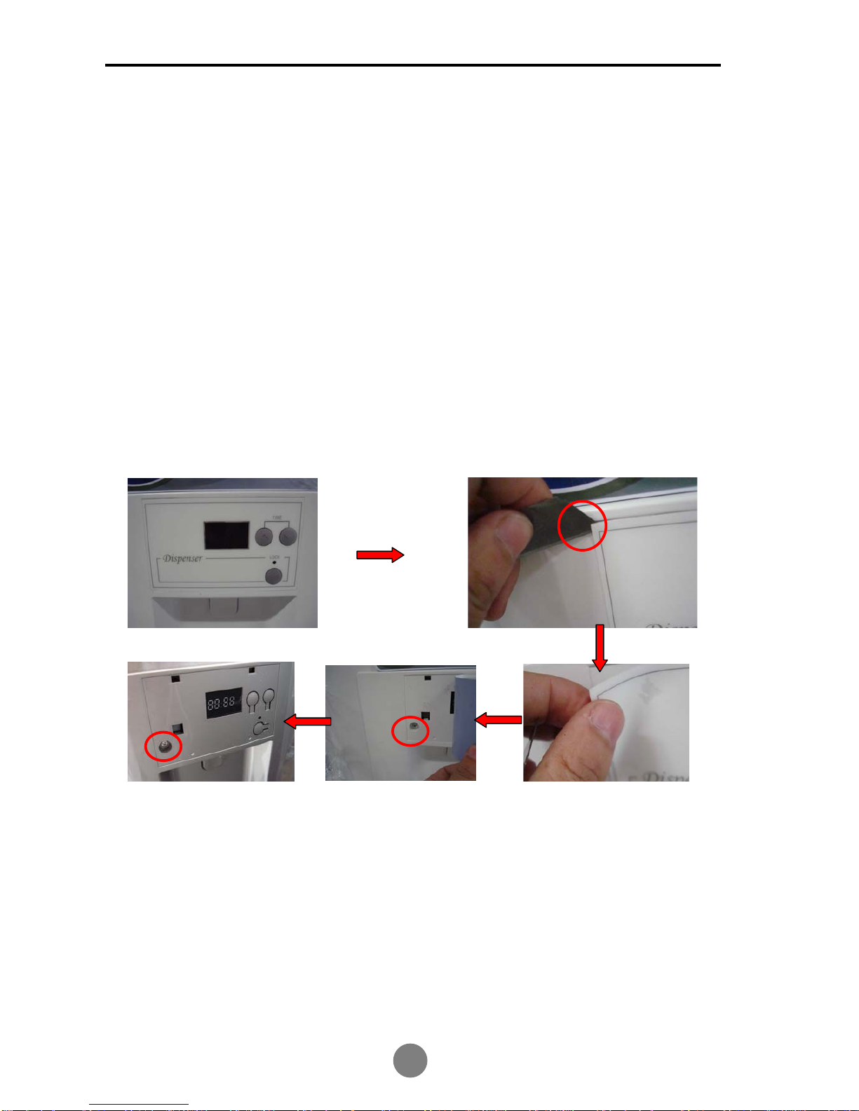
2.3 Dispenser Panel Label Removal-----------------------------------------------------4
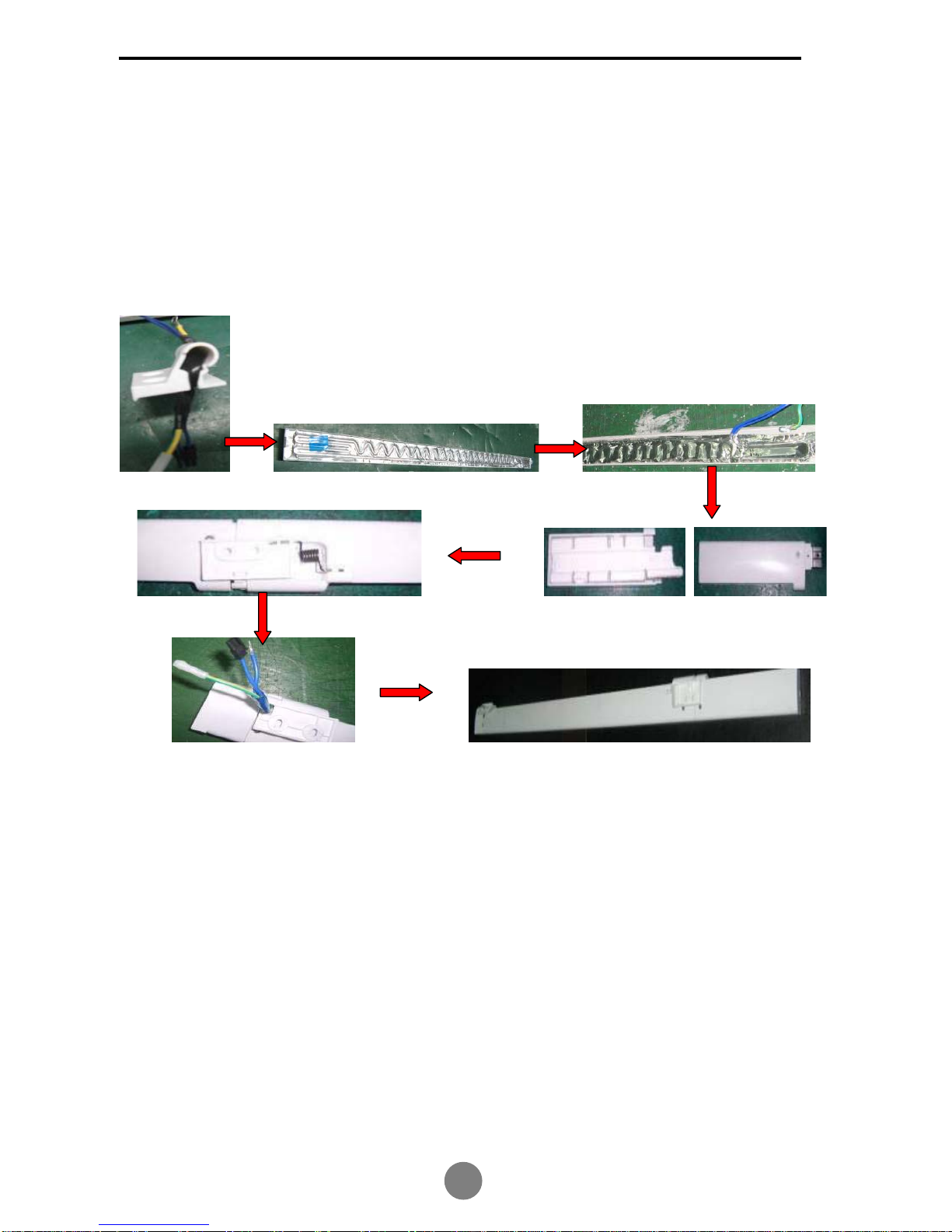
2.4 Mullion and Mullion Heater Replacement----------------------------------------5-7
2.5 Freeze Sensor Replacement----------------------------------------------------------8
3. CONTROL AND DISPLAY SYSTEM---------------------------------------------9~15
4. REFRIGERATION PRINCIPLE-------------------------------------------------------16
System flow chart and scenograph------------------------------------------------------16
5. CIRCUIT DIAGRAM----------------------------------------------------------------17~22
5.1 Schematic----------------------------------------------------------------------------17~19
5.2 Connect diagram-------------------------------------------------------------------20~22
6. Sensor and Error code-----------------------------------------------------------------23
7. TROUBLESHOOTING-------------------------------------------------------------24~37
7.1 Common Troubles in Refrigerators and Remedies------------------------24~35
7.2 Sensor Replacement-------------------------------------------------------------------36
7.3 Instruction of Check Variable Speed Compressor------------------------------37
8. Other(Icemaker and defrost details)--- ------------------------------------------38
CONTENTS

Model Designations
Bottom Mount
21 - 25 cu ft Refrigerator / Freezer
Details:
PRODUCT CODE and SERIES INTRODUCTION
P B F S 21 E D A S
S: Stainless E: Black P: White
A: Production series
D: Dispenser and Icemaker I: Icemaker
E: Elite S: Supreme T: Plus
21:Capacity
S: Spill-proof shelving
F: Four doors
B: Bottom Mount Freezer
P: Phoenix series R: Standard series

PARTS IDENTIFICATIONS
Freezer
&KLOOFROGVWRUDJHÀRRGOLJKW
:DWHU¿OWHU
'LDU\IRRGER[
Diary foChill-cold
storageUDFNRGER[
Liquid rack
Slide rack
Fruits and
VHJHWDEOHVER[
Gallon
bottled seat
Cooked-
IRRGER[
Ice-making
drawer
Deepfreeze
refrigeration big
drawer
Deepfreeze
fridge
Ice spoon
Ice-maker
Ice-meeting
drawer
Drawer
clapboard
Deepfreeze
fridge big
drawer
For the application of this brochure to different models, the characteristics of the refrigerator you are
using may be different from the descriptions in this brochure.
Note

2.1 Right French Door Removal and Installation
1. Remove the screws on the top hinge cover,then set aside the top hinge cover and
lay it down for installing later;
2. Using a screwdriver,remove the top hinge screws.Remove the hinge,then take the
door off and place it aside;
3. Remove the middle hinge if necessary;
4. Install the door in reverse sequence.
Left French Door Removal and Installation
1. Firstly,remove the top hinge cover as above;
2. Disconnect the water pipe from back of cabinet(just for those models with Water
dispenser);
3. Remove the hinge screws by a screwdriver,and take off the hinge,then remove the
door and place it aside,Disconnect the wire cable connector,ground wire,then pull
out the water pipe(just for those models with Water dispenser);
4. Remove the middle hinge if necessary;
5. Install the door in reverse sequence.
Remark:If the refrigerator without water dispenser,just disconnect the all the wire
connectors.
DISASSEMBLY

2.2 Center Freezer Drawer Removal and Installation
1. Firstly,open the door as far as possible,and take off the drawer, then remove the
screws fixing slideway on each side of the drawer;
2. Pull the drawer body up and towards you,then place it aside;
3. Remove the screws fixing the slideway fixture on door;
4. Install the drawer in reverse sequence.
Remark:the removal and installation of bottom freezer drawer are the same as above.
DISASSEMBLY

2.3 Instruction of removal Dispenser Panel Label on BM21 series
(Only for those models with Water Dispenser)
Tools Required:
Knife or sharp screwdriver
Warning: Please do protect the refrigerator!
Instruction:
1. Insert the knife under the panel label to remove the label.
2. Unrip the label (with the knife) about 8cm,then it’s easy to remove the whole label.
3. Remove the screw under the label.
Remark: The label can be used for several times.
DISASSEMBLY

2.4 Instruction of Assembling Door Mullion on BM21/25 series
1. Install top axis of mullion through the heater;
2. Paste the heater onto mullion;
3. Fix the earth wire;
4. Install the reinforce metal and foam on the bottom cover;
5. Fix the bottom cover on the mullion,then fix the spring,bottom axis,foam airproof;
6. Fix the top axis and top cover;
7. Fix the 5 screws.Preinstall mullion is OK.
DISASSEMBLY

Instruction of Replacing Door Mullion heater on BM21/25 series
1. Remove the screws on mullion;
2. Disconnect the earth wire and connector;
3. Remove the screws on mullion;
4. Remove the upper cover,seal and bottom cover;
5. Remove the screw fixing earth wire;
6. Tear off the heater and replace a new one.Then Install it according to the steps above.
Notice:
1. Be careful:the distortion of clip will cause gap between the bottom cover and mullion.
2. After reassembly mullion,run 5-10 minutes,feel surface of the mullion.If it’s not warm,check
the connection,and reconnect if necessary.
DISASSEMBLY

Instruction of Replacing Horizontal Mullion heater
1. Remove the screws fixing horizontal mullion;
2. Dismantle the horizontal mullion and foam airproof;
3. Disconnect the linking clip and mullion heater;
4. Remove the screw fixing earth wire of heater,then tear off the heater;
5. Install the horizontal mullion according to the above steps.
Notice: Be careful:the distortion of clip will cause gap between the airproof and horizontal
mullion
DISASSEMBLY

2.5 Instruction of removal FRZ sensor on BM21/25 series
1.Remove the FRZ airpassage cover;
2.Remove the rear gasket of FRZ airpassage cover,then you can see the FRZ sensor;
3.Take off the sensor from the clip;
4.FRZ sensor wire
5. Install the FRZ sensor according to the above steps.
DISASSEMBLY

CONTROL and DISPLAY SYSTEM
The dispenser display panel (Only for PBFS21****/PRFS25E*** series)
D A B
C
A-------Hour Button B-------Minute Button
C-------Lock Button D-------Time Area
WARNING: There is a hidden screw under the dispenser display panel.
The cabinet display panel
Control Panel for PBFS21****/RBFS21T***/PRFS25E*** models
E F G H I J K L M N
Control Panel for RBFS21S*** models
E F G H I J K L M
E------Express Freeze Button F.G--------Freezer Temperature Adjusting Button
H------Freezer Temperature Indicating Area I-----------Refrigerator Temperature Indicating Area
J.K----Refrigerate Temperature Adjusting Button L-----------Express Chill Button
M------Reset (or Test) Button N-----------Water Filter Change Indicating Lamp

CONTROL and DISPLAY SYSTEM
3.1 Lock and Unlock (Only for PBFS21****/PRFS25E*** series)
D A B
C
Press Button C: After the first chime, the light indicator lock is in effect, the clock settings
are fixed, and the function of getting cold drinks is locked; Press Button C again: After the
first chime, the light goes out, indicating the clock settings can be adjusted.
3.2 Refrigerator temperature adjustment
Control Panel for PBFS21****/RBFS21T***/PRFS25E*** models
E F G H I J K L M N
Control Panel for RBFS21S*** models
E F G H I J K L M
Press Button J or K: the refrigerator temperature indicating area will flicker. When the
temperature is set, the temperature range is 34 to 46 degree F. Each time you press
Button K, temperature will increase a level, until the highest level is reached; Each time
you press Button J, temperature will decrease a level, until the lowest level is reached.

CONTROL and DISPLAY SYSTEM
3.3 Freezer temperature adjustment
Control Panel for PBFS21****/RBFS21T***/PRFS25E*** models
E F G H I J K L M N
Control Panel for RBFS21S*** models
E F G H I J K L M
Press Button F or G: the freezer temperature indicating area will flicker. When the
temperature is set, the temperature range is -6 to 6 degree F. Each time you press
Button G, temperature will increase a level, until the highest level is reached; Each time
you press Button F, temperature will decrease a level, until the lowest level is reached.
3.4 Time clock adjustment (Only for PBFS21****/PRFS25E*** series)
D A B
C
In Unlocked mode, press Button A and B both for 3 seconds: There will be a chime and
then the time area will flicker. Press Button A to adjust hours between 1 and 12,If you
press Button A again when it is “12”, “1” will be shown. Press Button B to adjust minutes
between 00 and 59. If you press Button B again when it is “59”, “00” will be shown. AM
and PM will be conversion when the time area D shows 12:00 PM.

CONTROL and DISPLAY SYSTEM
3.5 Express Freeze setting
Control Panel for PBFS21****/RBFS21T***/PRFS25E*** models
E F G H I J K L M N
Control Panel for RBFS21S*** models
E F G H I J K L M
The function of Express-freeze is to freeze the food completely in the shortest time.
Press Button E: The Express-freeze button indicator will light, and the freezer will be in
Express-freeze mode. In next 3 hours, temperature cannot be changed. It will not drop
below set temperature. If you want to quit the Express-freeze mode, press Button E
again, it will reset to normal operation.
3.6 Express Chill setting
Press Button L: The Express-chill button refrigerator indicator will light, and the
refrigerator will be in Express-chill mode. It will remain in this mode for 3 hours, but if the
refrigerator temperature is 2 degree F lower than its desired temperature, the refrigerator
will stop the Express-chill mode. If you want to quit the Express-chill mode, press Button
L again, it will reset to normal operation.
ƷWhen the refrigerator is in the Express-freeze or Express-chill modes,within the set
time,the process of refrigerating remains constant without effecting power.

CONTROL and DISPLAY SYSTEM
3.7 Centigrade / Fahrenheit display conversion function
Control Panel for PBFS21****/RBFS21T***/PRFS25E*** models
E F G H I J K L M N
Control Panel for RBFS21S*** models
E F G H I J K L M
Press Button F, G, and J for 3 seconds: After the first chime, Centigrade Temperature
readings will be in effect. Press them for 3 seconds again, it will change to Fahrenheit
Temperature readings.
3.8 Water Fill adjustment
Press Buttons F, G, J, and K for 3 seconds: There will display water fill time on FRZ
temperature indicating area H, such as "65" means water fill time is 6.5 seconds. And
press Button F to decrease water fill time while Button G to increase water fill time. The
default setting of water fill time is 6.5 seconds.
3.9 Water filter change indicator setting
Filter change indicator N will active on 6 months interval as a reminder to change filter.
After changing filter, press RESET Button M, the indicator N will go out.

CONTROL and DISPLAY SYSTEM
3.10 DEMO mode
Control Panel for PBFS21****/RBFS21T***/PRFS25E*** models
E F G H I J K L M N
Control Panel for RBFS21S*** models
E F G H I J K L M
Press Button F, G and K for 3 seconds: The function of DEMO will be available. There
will be "_ _" on REF and FRZ temperature indicating area (H and I) just as below:
In the DEMO mode, when the REF door is opened, the REF lamp will be on and then
closed after 7 minutes, but the fan will be closed after 2 minutes when the REF door is
opened.
When the FRZ door is opened, the FRZ lamp will be on and closed after 7 minutes, but
the fan will be closed all the time.
If the REF and FRZ doors are both opened, the lamps will be on.
Besides, in the DEMO mode, the compressor and heater etc. will not be available.
3.11 ICEMAKER OFF/ON
Press Button G and J for 3 seconds: The Express Freeze indicator E will flicker, and the
icemaker will turn off. When you press Button G and J for 3 seconds again, the icemaker
will turn on.
Notice: In Express-freeze mode, if the icemaker is OFF, the “Express-freeze” indicator E
will repeat the following action: it will be on for 5 seconds and then blink for 3 times.

CONTROL and DISPLAY SYSTEM
3.12 Door ajar alarm
The function will be started when any door is opened for over 60 seconds. There will be
chime on 30 seconds intervals until all the doors are closed.
3.13 Display Panel Power Down
The cabinet display panel:
30 seconds after adjusting any button, the digital screen will go out automatically. If you
press any button or open any door or active water dispenser, the screen will light again.
The Dispenser display panel(Only for PBFS21****/PRFS25E*** series):
D A B
C
There are two modes as below:
1. LED screen light is on 24 hours;
2. 30 seconds after adjusting any button, the LED screen will go out automatically. If you
press any button or open any door or active water dispenser, the screen will light
again.
In LOCK mode, press Button A and B for 3 seconds to change the mode of dispenser
display panel. The first mode will be in effect when the refrigerator is electrified the first
time.
3.14 ERROR code indicator
When there is something wrong with the refrigerator, some Error code will be shown on
the REF and FRZ temperature indicating area (H and I), such as F1, F2, F3, F5, F6, Eh.
Please consult after-sale service.

REFRIGERATION PRINCIPLE
SYSTEM FLOW CHART
SYSTEM FLOW SCENOGRAPH
1
2
3
4
5
6 7
1.Compressor
2.Condenser
3.Dew Proof pipe
4.Dry filter
5.Capillary tube
6.Evaporator
7.Suction tube

5.1 Schematic
CIRCUIT DIAGRAM
This manual suits for next models
3
Table of contents
Other Haier Refrigerator manuals

Haier
Haier HRF-347F User manual

Haier
Haier HR-175U User manual

Haier
Haier HRF- 329AA User manual

Haier
Haier RF-8888-46 User manual

Haier
Haier HBX-IC User manual

Haier
Haier HFF750CGBJ User manual

Haier
Haier HFW7819EWMP User manual

Haier
Haier HRB227W User manual

Haier
Haier RF-8888-221 User manual

Haier
Haier HRF-229FABA User manual

Haier
Haier HB16FMAA User manual

Haier
Haier Aficionado M111 User manual

Haier
Haier HRC2731AC User manual

Haier
Haier HNSEW02 User manual

Haier
Haier HRF-628A 6 Series User manual

Haier
Haier HRF-339DVC User manual

Haier
Haier HYC-68 User manual

Haier
Haier PRTS Series User manual

Haier
Haier HSE04WNC - 03-05 User manual

Haier
Haier HRF-352A