Hailo HS8-R User manual

Shaft cover, flush, loads as per EN124 (Class B+D)
Chapter 01: Mounting dimensions Page 02
Chapter 02: Mounting / setting the cover in concrete Page 03
Chapter 03: Assembling the opening aids - gas springs Page 04
Chapter 04: Using the shaft cover Page 05
Chapter 05: Maintenance and servicing information Page 06
Page 1 / 6
Assembly and User Instructions
Hailo Type HS8-R Shaft Cover
Status: 30.08.2022

Page 2 / 6
Chapter 01: Mounting dimensions
The surrounding concrete edge required is derived from the customer’s structural calculations and
formwork and reinforcement plans. This is not a constituent part of these assembly instructions.
As a guideline, we recommend the following minimum thicknesses on all sides in addition to the
external dimensions of the shaft cover indicated below:
For stationary traffic (e.g. car park): 80mm
For flowing traffic (carriageway): 120mm
These dimensions must be respected at the rear, including behind the hinge boxes!
Minimum quality of concrete: C35/45, respecting the customer’s specifications!
Status: 30.08.2022

Round stainless steel chequer safety plate cover,
flush, load-bearing, load class according to EN124 B 150kN / D 400kN,
for setting in concrete, surface water tight, opening assisted by gas springs,
inc. mechanism for keeping the lid open
Page 3 / 6
IMPORTANT!!!
To avoid damage to the cover, it is absolutely essential to comply with the following instructions.
Hailo accepts no liability or warranty for damage caused by improper handling. The lid must sit
correctly in and be firmly screwed to the frame while the outer concrete surround is being created!
Otherwise there is a risk that the frame will move when the reinforcement is installed or when it is
set into the concrete. The correct and secure positioning of the lid may then no longer be
guaranteed. The lid must remain closed until the concrete has hardened! Only then is the cover
opened and the gas spring fitted.
1. The recess required in your structure is calculated as follows: External dimensions of the cover + min.
80 / 120mm all round for the concrete.
2. Remove the parts supplied from the cover, e.g. the gas spring, and any keys and closure parts. Lift
the shaft cover with suitable lifting tackle or equipment, such as a forklift, crane or digger, and insert it
into the recess provided.
3. Level the cover using a spirit level and place it at the required height. Any difference in height can
be compensated by putting shims under the frame. Make sure that the frame is lying straight. Make
sure the installation height takes account of additional road or footpath surfaces.
4. Once the cover is finally fixed, seal the gap all the way round between frame and structure (with a
wooden frame, sealing cord ...).
5. Make sure that the lid of the shaft cover is tightly closed while it is being concreted in. This prevents
the frame from getting out of shape. To safeguard against lifting and movement when concreting, the
cover can be secured using ballast.
6. The cover can now be finished off with a seal. We recommend compressing the concrete with
internal compactors. Allow for the setting times specified for the concrete.
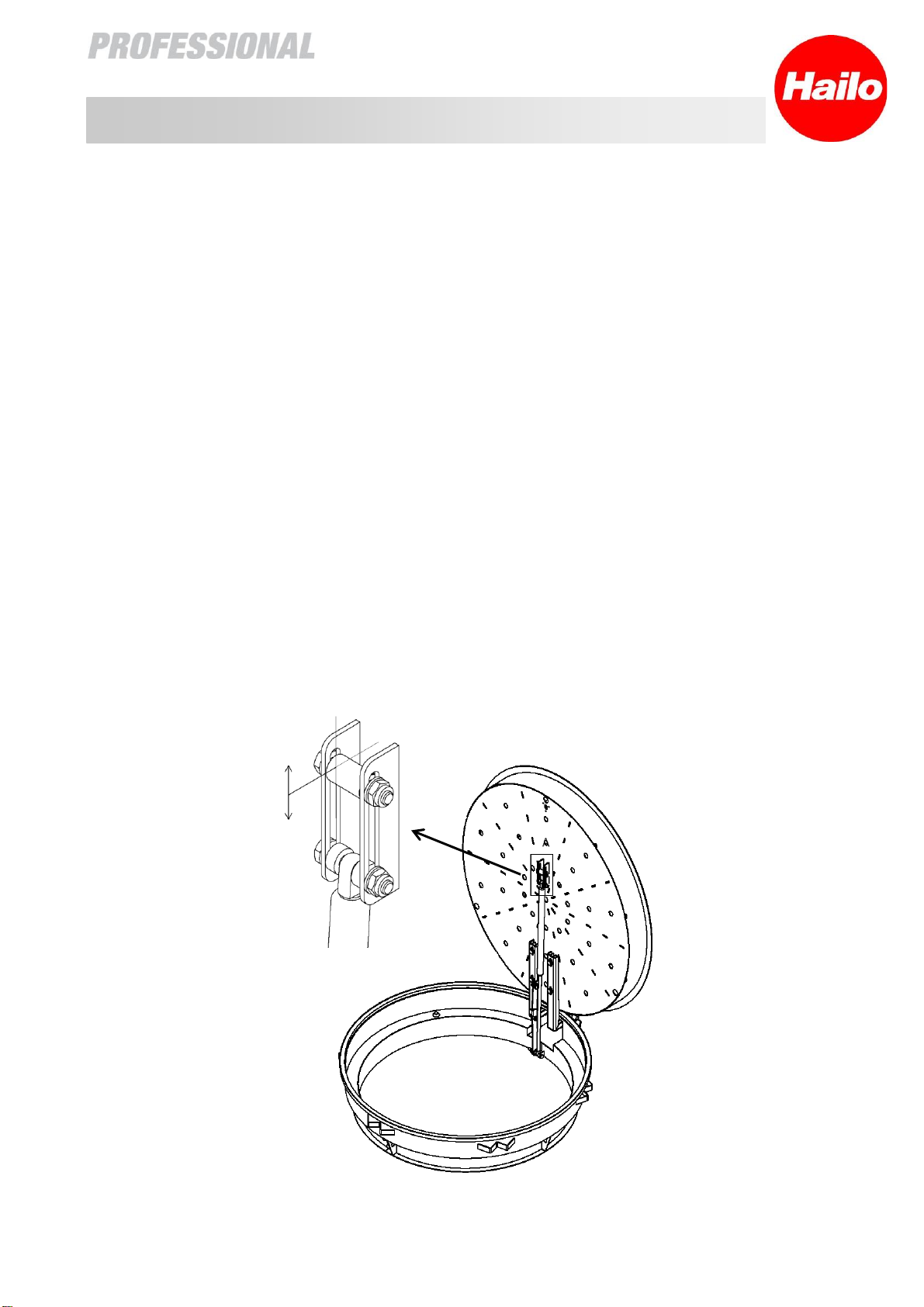
7. Once the concrete has hardened, the gas spring can be installed. The piston rod is always screwed
to the frame and the cylinder to the lid. The necessary means of attachment are pre-fitted.
8. Once all work has been completed, it is important to remove any concrete residue and dirt from the
frame and the lid. This ensures that your Hailo shaft cover will have a long and trouble-free service life.
Chapter 02: Mounting / setting the cover in concrete
Status: 30.08.2022

Page 4 / 6
Chapter 03: Assembling the opening aids - gas springs
The gas springs can be adjusted for force by fitting an adjustable stop (see illustration below).
1. First, screw the piston rod head to the frame at the bottom using the pre-fitted screw. Only tighten
the nut to a point where the screw can still be rotated!
2. Next, fit the head of the cylinder as illustrated. As the lid moves, the screw slides in the slot, so do not
tighten this nut firmly either.
3. By fixing the stop / sleeve at a variable height, it is possible to adjust the point to which the gas
spring also slides up when opening the lid.
If the shaft cover has only one gas spring, the point is to be chosen such that the lid stops when
opened at around 80°. It is then easy to move the lid manually into the latch locking position. The stop
is not required for lids with a depth of 600 mm. If multiple gas springs are used, it makes sense to fit the
stops in such a way that the gas springs are used in succession. The advantage of this is that, when
opening, the lid does not open too quickly and, when closing, there is no need to push immediately
against the force of all the gas springs. The further the stop is moved downwards, the greater the
force of the gas springs when opening starts.
Please note: Do not move the stop so far downwards that the piston of the gas spring comes into
contact with the base of the cylinder!
Height adjustable
Status: 30.08.2022

Page 5 / 6
Opening and closing the shaft cover
Chapter 04: Using the shaft cover
To use the shaft cover, you need an operator key (#9515031) and the key to the profile cylinder in
the locking insert (optional), if any.
1. Use the operator key to release the upper brass triangular locking screw(s) of the locking
mechanism(s) and store it (them) somewhere clean (figure 1).
2. Use the key to unlock and remove the locking insert, if any.
3. Release the lower brass triangular locking screw(s) (figures 2 and 3).
4. Use the key hook to reach into the opening in the neck of the lock and lift the lid (figure 4).
5. The gas springs assist opening up to approx. 80°; beyond that you must open the lid further by
hand until the latch engages.
6. To close, release the latch and perform steps 5 to1 in the reverse order.
Figure 1
Figure 2
Figure 3
Figure 4
Status: 30.08.2022

Page 6 / 6
1. The triangular locking screws are made of brass in order to prevent or exclude
"seizing" or cold welding of the screwed connection between the lid and frame.
2. The locking screws can be greased on the thread so that they can be freed more
easily if the shaft cover has not been opened for a prolonged period.
3. The seal must always be kept clean in order to avoid damage and the resulting loss
of sealing.
4. For that reason, always clean the seal around the frame and the stainless steel
contact surfaces between the lid and the frame with a hand-brush or cloth before
using the lid. The use of stainless steel removes the need to apply oil or grease.
This ensures that your Hailo shaft cover will have a long and trouble-free service life.
Chapter 05: Maintenance and servicing information
Status: 30.08.2022
This manual suits for next models
1
Table of contents
Popular Industrial Equipment manuals by other brands

Festo
Festo EXCM-40 -PF Series operating instructions

PAW
PAW HeatBloC K34R Installation and operation instruction

Pregis
Pregis AirSpeed SMART V3 Technical manual

Siemens
Siemens MAMMOMAT 3000 Repair instructions

Cantek
Cantek JDT-65 Operations & parts manual

Innovative Poultry Products
Innovative Poultry Products Talon Operator's Manual & Warranty

Norfield
Norfield STRIKE MASTER MFG 600 Operational instructions

AirBench
AirBench RP Series Operation and maintenance

Southwire
Southwire MAXIS MCF-01 Operating and maintenance instructions

Tsubaki
Tsubaki BSEU Series Installation and maintenance instruction

Siemens
Siemens UP 588/13 Technical specification

JST
JST MKS-L instruction manual