Hall Technologies FHD264 User manual

Hall Technologies 2019 UMA1269 Rev 2
Hall Technologies • 1234 Lakeshore Dr Suite #150 Coppell, TX 75019 • halltechav.com
FHD264 User Manual
Dynamic Virtual Matrix™, HDMI Distribution and Switching over LAN with RS-232 &
IR Extension
FHD264-S
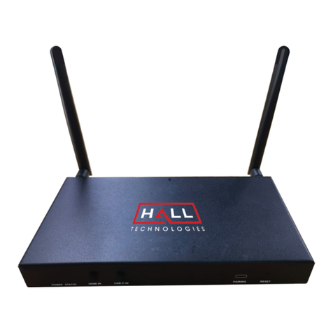
FHD264-R
Distribute up to 64 individual HDMI video sources to 250 displays or mor

2
© Copyright 2019 Hall Technologies
Contents
1.0 Introduction...................................................................................... 4
1.1 General...................................................................................................... 4
1.2 Features .................................................................................................... 5
2.0 Package Contents ............................................................................ 6
3.0 Installation .......................................................................................7
3.1 Configuration............................................................................................7
3.1.1 Point-to-Point ................................................................................. 7
3.1.2 Point-to-Many (Splitter) and Many-to-Many (Matrix) ..................7
3.1.3 Setup............................................................................................... 8
4.0 Front and Rear panel..............................................................................10
4.1 Font Panel Operation .............................................................................11
4.1.1 Changing IP address from Front panel ......................................11
4.2 WebGUI ...................................................................................................12
4.3 Telnet Control.........................................................................................13
4.4 Dynamic Virtual Matrix Manager Tool ..................................................16
4.5 CNT-IP-264 .............................................................................................17
5.0 Features ......................................................................................... 18
5.1 Device ID .................................................................................................18
5.2 Group ID ..................................................................................................18
5.3 OSD Menu...............................................................................................19
5.4 RS-232.....................................................................................................19
5.4.1 Working ........................................................................................20
5.5 Serial Over IP (SoIP) from External Devices.........................................20
5.6 Fail-Safe (FS) Video Routing .................................................................21
5.7 IR .............................................................................................................22
5.8 Video Scaling and Bit Rate Control .......................................................22
5.8.1 Scaler and Encoder Settings.......................................................23
5.9 EDID.........................................................................................................23
5.10 Power over Ethernet (PoE) ..................................................................24
6.0 Firmware Upgrade..................................................................................25
6.1 Factory Default.......................................................................................25
7.0 FAQ & Troubleshooting .................................................................. 26
7.1 Contacting Hall Research ......................................................................27
8.0 Specifications................................................................................. 27
TRADEMARKS USED IN THIS MANUAL
Halle Technologies and its logo are trademarks of Hall Technologies. Any
other trademarks mentioned in this manual are acknowledged as the
property of the trademark owners.

© Copyright 2019 Hall Research, Inc.
3
FCC RADIO FREQUENCY INTERFERENCE STATEMENT
This equipment generates, uses, and can radiate radio frequency energy and
if not installed and used properly, that is, in strict accordance with the
manufacturer’s instructions, may cause interference to radio
communication. It has been designed to comply with the limits for a Class A
computing device in accordance with the specifications in Subpart B of Part
15 of FCC rules, which are intended to provide reasonable protection against
such interference when the equipment is operated in a commercial
environment. Operation of this equipment in a residential area is likely to
cause interference, in which case the user at their own expense will be
required to take whatever measures may be necessary to correct the
interference.
Changes or modifications not expressly approved by the party responsible
for compliance could void the user’s authority to operate the equipment.

4
© Copyright 2019 Hall Technologies
1.0 Introduction
1.1 General
The FHD264 is a family of HDMI over LAN Senders (encoders) and Receivers
(decoders). They utilize advanced video encoding techniques and can
distribute up to 64 Full-HD video signals to hundreds of displays on a simple
1 Gigabit local area network (LAN). Senders and Receivers can also extend IR
remote control signals and Full duplex Serial RS-232 communications.
Each device provides a two-line front panel LCD that can be used to easily
configure or monitor parameters such as IP settings, multicast group
selection, assignment of device names, and more. This eliminates the usual
installation challenges of finding and configuring devices on the network for
the first time. With the front panel LCD, users can see and assign
configuration parameters with ease.
HDMI Audio is extracted and available as convenient 3.5mm sterefo analog
output on both the FHD264 Sender as well as the Receiver. The FHD264-S
Sender also provides local HDMI output.
The RS-232 serial port on each device can be used in SoIP mode (Serial over
IP) allowing IP controllers on the network to communicate with and control
peripheral equipment such as Display and projector using Serial Commands.
All devices support IEEE 802.3af PoE (Power over Ethernet). When
connected to a network switch with PoE, no external power supply is
required. A power supply is included for customers that may not have PoE on
their network.
The FHD264-R Receivers can decode the video from any Sender on the LAN.
It is easy to switch the Receiver between Senders. This can be done in
several ways:
•Using front panel LCD and push buttons
•Using supplied IR Remote Control
•Browsing to the WebGUI in each unit
•Telnet Commands (ideal for third-party control of switching)
•Windows™ PC running DVM Manager Tool software
(free download)
•CNT-IP-264 (Optional Network Controller module
that can globally control all FHD devices and third
party devices on the network)
Receivers include an IR remote controller for switching among
Sender channels (multicast groups). In installations such as sports bars,

© Copyright 2019 Hall Research, Inc.
5
users can easily switch the monitor to another source using this IR remote. In
addition, since the FHD264 extends IR signals, users can control sources
such as video players using that device’s original IR remote. In other words,
from the Receiver location (at the TV), you use the included IR remote to
switch the video to a different Sender, then you can use
the IR remote of whatever source is connected to the
sender.
Receivers also offer Fail-Safe automatic video routing
and redundancy. So if the receiver is not detecting any
video on its currently assigned channel, it will switch to
a user defined alternate channel. It can also automatically switch back to the
original multicast channel if video is detected again.
Senders are available as a stand-alone box. Rack mount hardware is also
available for housing up to 12 senders in 4U rack space.
FHD264 applications include digital signage, meeting rooms, classrooms,
bus & metro stations, airports, home theater, and more.
Figure 1 - Block Diagram
Showing Senders on the left with local monitors connected and Receivers on the right
1.2 Features
•Create a virtual video matrix with up to 64 Senders and 256 Receivers
•Works on affordable 1Gig network infrastructure
•Front panel LCD for configuration of IP parameters, and status indication
•HDMI loop output connector on FHD264-S Sender

6
© Copyright 2019 Hall Technologies
•HDMI Audio extraction at both Sender and Receiver with convenient L/R
stereo analog 3.5mm outputs
•PoE enabled. Does not require power supply connection if plugged to the
PoE switch
•Fail-Safe video routing to create automatic AV system redundancy
•Video Scaler in Sender to manage bandwidth
•Bi-directional RS-232 extension from sender to all receivers in same group
•IR (infrared) extension from receivers to paired sender
•Serial Over IP(SoIP) to control companion serial devices
•IR Remote Control for pass through and local control
•HDMI audio extraction at both Sender and Receiver end
•Front Panel with LCD and buttons to display device information and
change IP configuration
•Easy to use WebGUI in each unit, accessible from any browser
•Free Windows™DVM Manager Tool software (for system-wide
configuration and video switching from one GUI)
•Each device can have a user-definable name (e.g. Lobby Display,
Projector)
•Low power consumption (less than 3 W)
•Supports SD, HD and Full-HD (1080p@60 Hz) resolutions
•HDCP 1.4 compliant
2.0 Package Contents
(1) Model FHD264 (-S, -R)
(1) 5V DC Power Supply with universal plug adapter kit
(1) IR Emitter Cable with Senders
(1) IR Detector Cable with Receivers
(1) IR Remote Controller with Receivers
(1) Set of L-bracket mounting hardware (-S and -R)
(1) User’s Manual

© Copyright 2019 Hall Research, Inc.
7
3.0 Installation
For installations having multiple Senders and Receivers, a dedicated Gigabit
(1000 BaseT) network with PoE and IGMPV2 Support is required. The H.264
encoding scheme allows user-definable bit rates to give users control over
bandwidth used for each video stream. Use CAT5e/6 cables to extend up to
394 ft (120 meters).
3.1 Configuration
FHD264 system supports multiple configurations: point-to-point (one Sender
connected to one Receiver without network switch), point-to-many (one
Sender to many Receivers like a video splitter), and many-to-many (matrix
operation). Typically, both point-to-many and many-to-many configuration
requires a network switch.
3.1.1 Point-to-Point
Point-to-Point is the straightforward configuration of FHD system without
involving a network switch. An external power supply is required to supply
power to both Sender and Receiver. The only requirement is that the TX and
RX should have unique IP address (Static) and need to be in the same group.
Figure 2 - Example: Point-to-Point
3.1.2 Point-to-Many (Splitter) and Many-to-Many (Matrix)
Start by setting a unique IP address (if not using DHCP) and Multicast Group
channel for each of the Senders (see the front panel operation in Section
4.2.) Duplicate IP addresses and Multiple Senders on the same Group will
cause conflicts. Receivers must also have unique IP addresses, but can point
to the same Group channel.
Receivers with the same group number as a Sender will show the video from
that Sender, and RS-232 and IR are routed between them. To use a broadcast
TV analogy, Multicast Group numbers are like TV channel numbers. Only one
station can broadcast on a given channel, but many Receivers can be tuned
to that same channel.

8
© Copyright 2019 Hall Technologies
As shipped, each device is configured for DHCP. In this mode, when powered
up each box gets its IP address from the DHCP server on the network.
Alternately, the IP addresses can be assigned manually and set to Static
from the front panel. To change IP address using the PC-GUI, connect a
Windows™ PC or laptop to the network and run the free DVM Manager Tool.
Figure 3 - Example: Point-to-Many
3.1.3 Setup
1. To get started, use a Gigabit Switch with DHCP server and IGMPV2
Support (Recommended)
2. If the switch does not support PoE, use the power supply included in the
package (-S and -R) to power the FHD.
3. By default, DHCP is enabled in both Sender and Receiver. The default IP
address of the Sender is 192.168.1.11 and Receiver is 192.168.1.12.
(See Section 5.11 Factory Defaults for more details.)
4. If the switch supports DHCP, connect the Senders(s) using CAT5e/6
cable.
5. If the switch does not support DHCP, connect the Sender(s) (one at a
time) using CAT5e/6 cable and assign unique static IP address to each
device by turning OFF DHCP. (See Section 4.2.1 Changing IP address
from Front panel). Repeat the same step for all the Receiver(s).
6. Make sure each Sender has a unique Group ID. Note that, two Senders
cannot reside in the same Group ID. This will cause conflicts.
7. Connect HDMI source(s) to the HDMI input of the Senders(s).
NOTE A Gigabit(1000BaseT) Switch with DHCP server, IGMPV2 and PoE is
recommended. When there is more than one Sender on the network in a matrix
configuration (multipoint-to-multipoint) the Ethernet Switch MUST support: IGMP to
prevent network flooding.
Hall Research recommends using the Cisco SG300 Series of gigabit Ethernet Switches.

© Copyright 2019 Hall Research, Inc.
9
8. Connect the HDMI loop output of the Sender(s) to local HDMI display(s)
if desired.
9. Connect the HDMI display(s) to the Receiver(s) output and change the
Group ID of the Receiver(s) as required. To receive the video, both Sender
and Receiver must be in the same group. (If there is any problem with the
video, see FAQ Q2: No picture on the display.)
10. If using IR, connect the IR emitter cable into “IR OUT” port of the Sender,
and connect the IR detector cable into “IR IN” port of the Receiver.
11. If using RS-232, connect an RS-232 cable from the PC or automation
system to the supplied phoenix connector, and then connect it to the RS-
232 port on the Sender. Repeat the same process between the Receiver
and the device to be controlled. Note that the baud rate is selectable and
should be the same at both Sender and Receiver end. (See Section 4.1
Front Panel Operation for more details.)
12. Once the Senders and Receivers are configured properly on the network,
they will be discoverable by Hall Technologies’ DVM Manager Tool.
Simply plug a laptop or PC into the same router/switch and run the free
Windows™DVM Manager Tool. You can easily assign user-friendly
names to each device and change the Group routings.
13. To use the DVM Manager Tool to control video routing, first scan for the
devices. Note that if the switch does not support DHCP, then the IP
address of the PC also needs to be changed to static (See FAQ Q3: How
to Change the IP address of the PC?)
14. To access the internal WebGUI of FHD264, type the IP address into the
address bar of any standard browser. By default, as shipped from the
factory, no login is required to access the internal WebGUI. If login is
enabled, the default user name/password is admin/admin.

10
© Copyright 2019 Hall Technologies
4.0 Front and Rear panel
Figure 4 - Sender Front and Rear Panels
Figure 5- Receiver Front and Rear Panel
MENU: To view or change the system Configuration
NAV Keys: Navigation keys
RESET (RST): Press and release to reboot (same as power cycle). Press and
hold for 10 seconds to restore factory defaults.
5V DC: Plug the supplied 5V DC power supply to the unit, if PoE is
unavailable.
HDMI OUT: This is a local HDMI loop out for a local display.
HDMI IN: Connect to the HDMI source such as a DVD or Blu-ray player.
IR OUT: Connect to the supplied IR emitter cable.
AUDIO OUT: HDMI audio extraction
RS-232:Connect to PC/Serial Controller or displays with phoenix adaptor
1000BT: Connect to a gigabit network router/switch or a Receiver using
CAT5e/6 cable. The green LINK LED illuminates to show the link from
Receiver is established.
IR IN: Connect the supplied IR detector

© Copyright 2019 Hall Research, Inc.
11
4.1 Font Panel Operation
Use the front panel to change the Group ID, IP Configuration and RS-232
Baud Rate. By default, after the FHD264 gets initialized, it shows the home
screen with Device ID and Group ID. To see the system configuration, click
the MENU Button and use the NAVIGATION (NAV) keys to view various
settings. To change the settings, hold the MENU button until the setting
name starts blinking. Use NAV keys to change the parameters of the setting
and click MENU to apply setting or Hold MENU to discard setting. Follow the
messages on the LCD for further instructions.
Figure 6 - Front panel operation
4.1.1 Changing IP address from Front panel
To change the IP address from the front panel, make sure DHCP is turned
OFF. The steps are as follows
1. From Home Screen push MENU
2. NAV to IP configuration ("-- IP--")
3. Hold MENU until setting name ("--IP--") starts blinking
4. By default, the first octet in the IP address starts blinking
5. Use NAV keys to change the octet parameter or click MENU to move
to the next octet
6. After the reaching the 4th octet, click MENU to change the IP
address.
7. At any point time, if the setting name is blinking, hold MENU to
discard the changes

12
© Copyright 2019 Hall Technologies
4.2 WebGUI
The WebGUI can be used to change the following configuration settings:
•Device Info -- Device ID, Group ID
•Password -- Enable Login, Change Password
•RS-232 Baud Rate
•Firmware Upgrade
•Network Settings
•Scaler Settings (only for Sender)
•Encoder Settings (only for Sender)
•System Settings (only for Receiver) -- Fail-Safe, OSD, Debug (for
troubleshooting)
Both encoders and decoders can be password protected with a User Login,
which is enabled from the WebGUI.
Figure 7 –FHD264 Login Page
Default Username is admin and password is admin

© Copyright 2019 Hall Research, Inc.
13
Figure 8 - Sender WebGUI
Note: Changing IP configuration settings via WebGUI requires a Reboot in
order to take effect.
Figure 9 - Receiver WebGUI
4.3 Telnet Control
FHD264 offers an extensive telnet control instruction set to provide full
control of the system. The default telnet port is 9999. When connected, the
following prompt will be displayed on the terminal:

14
© Copyright 2019 Hall Technologies
Figure 10 - Telnet terminal message
Note:
•Commands are case sensitive - use lowercase characters as shown.
•Invalid commands result in “Unknown Input Command !!!”
•The “list <CR>”command displays the list of available commands.
All Commands are
Terminated by <CR><LF>
(or Hex 0D 0A)
Response
Function
set_group_id n
where n=0-1023
OK –Success
Error –Fail
Set Group ID
get_group_id
n
where ‘n” returns the group ID
Query the current group ID
status
set_dhcp
OK –Success
Error –Fail
Set to DHCP mode
get_dhcp
On –DHCP
Off –No DHCP
Query the DHCP status
Set_uart_baudrate n
Where n = 2400, 4800, 9600, 19200,
28800, 28400, 57600, 115200
OK –Success
Error –Fail
Set the baud rate for the
RS-232 on the unit
get_uart_baudrate
n
where n = baud rate
Query the current baud rate
setting in the unit
set_static_ip ip [ip(n.n.n.n)]
netmask [ip(n.n.n.n)]
gateway [ip(n.n.n.n)]
Where:
ip [ip(n.n.n.n)] =IP xxx. xxx. xxx. xxx
netmask[ip(n.n.n.n)]=netmask
255.255.xxx.xxx
gateway [ip(n.n.n.n)] = gateway xxx.
xxx. xxx. xxx
OK –Success
Error –Fail
Set the static IP
configuration for the unit
get_static_ip
IP: 192.168.1.xx
Netmask: 255.255.0.0
Gateway: 192.168.1.1
Returns the current static
IP configuration
get_mac_address
XX: XX:XX:XX:XX:XX
Query the MAC address of
the unit
get_lan_status
Link_Up/Link_Down
Query LAN Status whether
device is UP and
connected to the switch
get_ip_config
IP: XXX.XXX.XXX.XXX
Netmask: XXX.XXX.XXX.XXX
Gateway: XXX.XXX.XXX.XXX
Shows IP Configuration
settings

© Copyright 2019 Hall Research, Inc.
15
All Commands are
Terminated by <CR><LF>
(or Hex 0D 0A)
Response
Function
get_hdcp_status
On/Off
Where On - Input Video with HDCP
Off- Input Video without HDCP
Query the HDCP status of
the video input
get_video_lock
Lock
Unlock
Where Lock –Stable Input Signal
Unlock - No input video or
unstable
Query the video stability
status
set_session_key [0xhhhh(1~32)]
OK-Success
Error-Fail
Where
[0xhhhhh(1~32)]=0x000000~0xff
ff
Set session key for
encryption
set_screen off|on (Receiver ONLY)
Where off=blank on=unblank
OK –Success
Error –Fail
Set video blank/unblank
the screen
get_screen (Receiver ONLY)
on
off
Query the device output
status
set_page_login [string(off|on)]
where off = Disable login for the web
page session (default)
on= Enable login for theweb page.
OK –Success
Error –Fail
Set the login page for the
WebGUI
get_page_login
on
off
Query the webpage” login
enable” status
set_video_bitrate (Sender ONLY)
[string(fhd|hd|sd)][n(2000~18000)]
Where:
string(fhd|hd|sd)][n(100~25000)] can
be fhd, hd, sd and 12000
For example:
set_video_bitrate fhd 12000
OK –Success
Error –Fail
Set the max bit rate for the
TX to sender over the
network. Limits apply see
Section 10
get_video_bitrate [string(fhd|hd|sd)]
(Sender ONLY)
xxxx
Query the bit rate for the
TX
set_downscale_mode
string(fhd|hd|sd)] to
string(fhd|hd|sd)]
OK –Success
Error –Fail
Scale down the input video
to lower resolution
get_downscale_mode
string(fhd|hd|sd)]
(Sender ONLY)
string(fhd|hd|sd)]
Get the downscale mode
status
set_video_out_mode
string(both_on|loopthrough|network|
both_off)] (Sender ONLY)
OK –Success
Error –Fail
Enable the HDMI output
and network output
get_video_out_mode
(Sender ONLY)
string(both_on|loopthrough|netwo
rk|both_off)]
Query the Loop and
network output status
set_osd [string(auto|on|off)]
Auto= OSD will turn off when there is
an input signal detected.
On or Off –OSD Stays on or off
forever
OK –Success
Error –Fail
Set OSD mode of the
system
get_osd
Auto
On
Off
Query the OSD mode
status

16
© Copyright 2019 Hall Technologies
All Commands are
Terminated by <CR><LF>
(or Hex 0D 0A)
Response
Function
set_device_name [string (1~30)]
Where string can be 30 characters
long
OK –Success
Error –Fail
Set the device name
get_device_name
[string (1~30)]
Query the device name
get_fw_version
Tx/Rx Firmware : x.x.x.x.xxxxxxxx
Returns the firwmare version
Query the firmware version
factory_reset
Processing factory reset!
System will reboot after few sec!
Factory reset the device
Reboot
System will reboot after few sec!
To reboot the unit
get_company_id
xxx
Query the company ID
set_streaming_mode
[string(unicast|multicast)]
OK –Success
Error –Fail
Set the streaming mode of
the device
get_streaming_mode
[string(unicast|multicast)]
[string(unicast|multicast)]
where unicast means one-one
configuration and
multicast means one to many and
many-to-many configuration
Query streaming mode
status
master_get
xxx.xxx.xxx.xxx (IP Address)
[Blank]
Return the IP address of
registered 3rd party
controller for SoIP
master_set
[string(xxx.xxx.xxx.xxx)]
Master Set
Registers the IP address as
3rd party controller. All the
responses from the serial
device connected to RS-
232 port will be sent to the
server on port #5050 at
this IP address
rs_out
[string( up to 100 char)]
SoIP Sent
Outputs the string the
string via RS-232
get_failsafe (Receiver ONLY)
on
off
Returns the fail safe status
set_failsafe
[string(on|off)] (Receiver ONLY)
Ok -- Successes
Error -- Fail
Set the fail safe status
set_fs_group n
where n = 0 to 63 (Receiver ONLY)
Ok -- Successes
Error -- Fail
Set the fail safe group
number
get_fs_group (Receiver ONLY)
Number in range 0 to 63
Returns the fail safe group
number
Exit
Exits the telnet session
4.4 Dynamic Virtual Matrix Manager Tool
•The free Hall Research Windows™ Dynamic Virtual Matrix Manager
Tool can locate all the FHD264 devices on the network.
•It will list all the devices found by User-defined names, IP addresses,
and Multicast Group channels.

© Copyright 2019 Hall Research, Inc.
17
•Columns can be sorted (for example you can sort by device name).
Senders are listed on the left and Receivers on the right.
•Click the “Update” button after making any changes.
•Click the “Reboot” button to reboot the device.
Figure 11 - PC GUI
4.5 CNT-IP-264
The CNT-IP-264 is a powerful networking module designed to manage
Models FHD264 and HHD264 - HDMI over LAN Senders and Receivers. Users
can access the web application using any computing device (PC, Smart
phone or Tablet) that runs a standard browser. CNT-IP-264 has following
features:
•Embedded WEB Server with Graphical User Interface
•Monitors FHD264/HHD264 video routing and status
•Controls External Devices over Serial (SoIP), Telnet or TCP
•Create custom control for external devices
•Real time event scheduling with Real‐Time clock
•Compatible with Hall Technologies Device Finder utility
•Supports DHCP

18
© Copyright 2019 Hall Technologies
Figure 12 - CNT-IP-264
5.0 Features
5.1 Device ID
Each FHD264 Sender and Receiver can store a custom name of up to 31
alphanumeric characters. Naming the device is very useful in managing large
installations. The Device ID will be displayed on the front panel home screen,
OSD, WebGUI and FHD software applications. The default Sender name is
HRTVTX and Receiver is HRTVRX.
5.2 Group ID
A Group ID is a number range from 0 to 63, which the Sender uses to
multicast its video and data to a group of Receivers on the network. Each
group ID is linked to a multicast IP address. You can have a maximum of 64
sources (Senders) in the network. Note that there is no limitation on the
number of Receivers that can connect to a Group if they have a different IP
address.

© Copyright 2019 Hall Research, Inc.
19
5.3 OSD Menu
Figure 13 - OSD (Receiver ONLY)
The FHD264 Receiver shows the following information as an On Screen
Display (OSD). The OSD can be configured as Auto (Default), ON, OFF.
RX Name
This is Receiver’s user defined name
RX IP
This is Receiver’s IP address
TX Name
This is Sender's user-defined name to which the receiver
is connected
TX IP
This is Sender's IP address
Group ID
This is Receiver's multicast group
Status
"Waiting for connection ..." -- if there is no TX available in
its group
"Connected" -- TX found and receiving video
If the Receiver is connected and there is no HDMI source
at the Sender end, the following video will be generated
by the Sender by default.
5.4 RS-232
RS-232 communication in the FHD264 is bi-directional and
it is achieved using Serial Over IP(SoIP) Protocol. The
controller or the controlled device can be either at the
Sender’s or the Receiver’s end. Note that the Sender and
Receiver should have matching baud rate for
communication. The baud rate for the TX and RX can be
configured from Front Panel, WebGUI, or the Windows™ GUI.

20
© Copyright 2019 Hall Technologies
Figure 14 - RS-232 Communication
5.4.1 Working
When a serial device connected to the sender transmits data, it is received by
all the receivers in that group. If a serial device connected to the Receiver
transmits data, it will be received only by the Sender in that group. While
receiving data from multiple Receivers, the Sender receives the data on a
first come, first served basis and the receiver might not send all the data in
single IP Packet. To effectively parse the response from multiple serial
devices connected to the sender, enable Packet Mode at the Sender
(FHD264-S) and add Message Complete Delay (MCD) at the Receiver
(FHD264-R).
Packet Mode at the Sender will append a SOIP header for each chunk of data
received from the receiver. To avoid the fragmentation of SOIP messages
from the receiver use Message Complete Delay (MCD) at the Receiver end.
MCD tells the receiver to buffer the bytes received from the serial device
locally for certain period of time, until Serial device stops transmitting or
Buffer is full.
See Application Notes on Packet Mode & Message Completion Delay for more
information.
5.5 Serial Over IP (SoIP) from External Devices
Serial devices connected to the RS-232 port on FHD264 units can be
controlled over the IP network. SoIP commands can be issued via Telnet,
which is simplex (See the telnet command "rs_out" in telnet control).
This manual suits for next models
2
Table of contents
Other Hall Technologies Switch manuals
Popular Switch manuals by other brands

Brocade Communications Systems
Brocade Communications Systems VDX 6940 Series Hardware installation guide

ADTRAN
ADTRAN NetVanta 1224R Support note

Avaya
Avaya Ethernet Routing Switch 8300 Series Installation

Vertiv
Vertiv Cybex SC KM 120 Installer/user guide

IOGear
IOGear MiniView GCS632U installation manual

Cisco
Cisco 2975 - Catalyst LAN Base Switch Software configuration guide