Hall Technologies HSM-88-4K User manual

Hall Technologies 2019 UMA1269 Rev 2
Hall Technologies • 1234 Lakeshore Dr Suite #150 Coppell, TX 75019 • halltechav.com
HSM-88-4K User Manual
4K 8x8 HDMI Matrix Switcher
•Supports 4K UHD resolution
•HDCP 2.2 and 1.4 compliant with EDID Management
•Fast-Switch™ Technology
•RS-232, IP, IR and Front panel Control with Status LCD Display
•Uses Hall Technologies Genesis™ Control Command Set (GCCS)

1
© Copyright 2018 Hall Technologies.
Table of Contents
1.0 Introduction................................................... 3
1.1 General .............................................................. 3
1.2 Features............................................................. 3
2.0 Package Contents.......................................... 3
3.0 Configuration and Operation .......................... 4
3.1 Connection Diagram ......................................... 4
3.2 General Operation ............................................. 5
3.3 Presets (Memorized Routing Patterns) ............ 8
3.4 Using the IR Remote to route video ................ 10
3.5 Rear Panel ....................................................... 10
4.0 EDID management ....................................... 11
4.1 EDID Configuration.......................................... 11
4.2 Compute EDID ................................................. 12
5.0 Network Settings ......................................... 12
6.0 Serial & Telnet Commands........................... 13
7.0 Troubleshooting .......................................... 16
7.1 Contacting Hall Technologies......................... 16
8.0 Specifications.............................................. 17

2
© Copyright 2018 Hall Technologies
TRADEMARKS USED IN THIS MANUAL
Hall Technologies and its logo are trademarks of Hall Technologies. Any
other trademarks mentioned in this manual are acknowledged as the
property of the trademark owners.
FCC RADIO FREQUENCY INTERFERENCE STATEMENT
This equipment generates, uses, and can radiate radio frequency energy and
if not installed and used properly, that is, in strict accordance with the
manufacturer’s instructions, may cause interference to radio
communication. It has been designed to comply with the limits for a Class B
computing device in accordance with the specifications in Subpart B of Part
15 of FCC rules, which are intended to provide reasonable protection against
such interference when the equipment is operated in a commercial
environment. Operation of this equipment in a residential area is likely to
cause interference, in which case the user at their own expense will be
required to take whatever measures may be necessary to correct the
interference.
Changes or modifications not expressly approved by the party responsible
for compliance could void the user’s authority to operate the equipment.

3
© Copyright 2018 Hall Technologies.
1.0 Introduction
1.1 General
As a member of Genesis Digital Matrix™ series of switchers, the HSM-88-4K
matrix provides exceptional quality, intuitive operation and powerful control
methods that are hallmarks of Hall Technologies’ video matrix switches.
The HSM-88-4K is an 8x8 cross-point switch in a compact 1-RU enclosure. It
supports HDMI resolutions up to 4K @ 30 Hz 4:4:4 and 4K @ 60 Hz 4:2:0. It
also supports HDCP 2.2 and 1.4, 3D, deep-color. PCM, Dolby, DTS, and HD
audio standards. The matrix intelligently calculates EDID for each input
based on the EDID of the connected sinks.
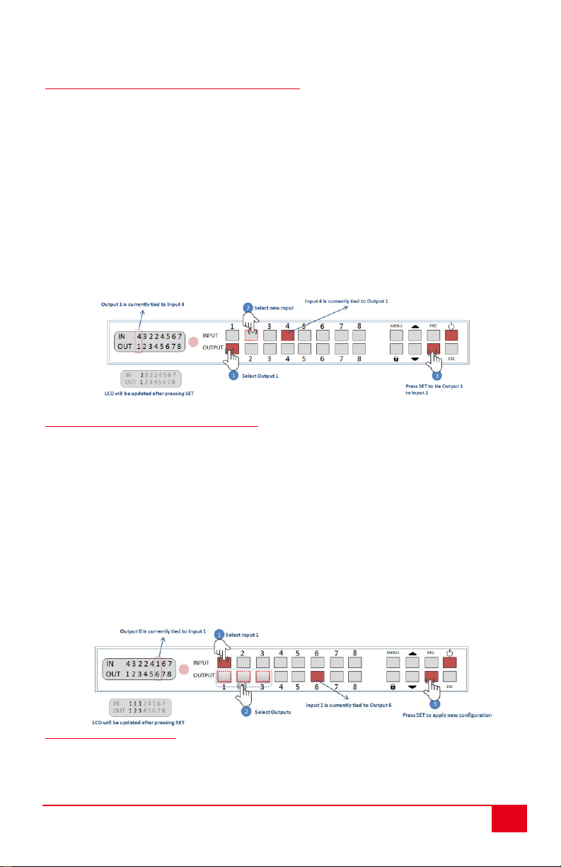
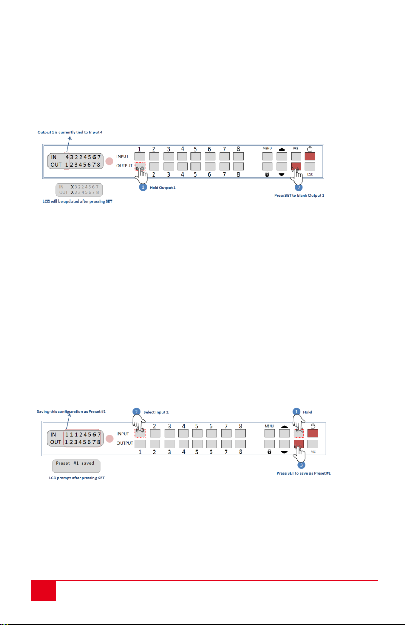
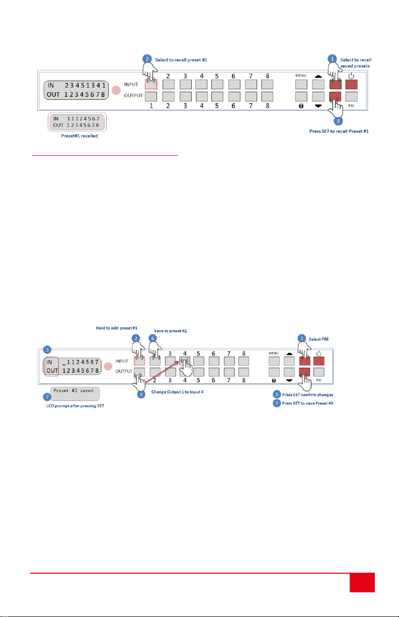
Users are able to save and recall multiple matrix routing configuration
PRESETs. HDMI outputs can also be blanked. The matrix includes a two-line
character LCD on its front panel in order to display the current video routing
and to facilitate creating or recalling Presets.
The HSM-88-4K matrix is ideal for conference rooms, multimedia
presentations, digital signage, houses of worship, and many other settings.
1.2 Features
•Supports 4K UHD resolution
•HDCP 2.2 and 1.4 compliant
•Fast-Switch™ technology
•RS-232, IP, IR and intuitive front panel control
•Two-line character LCD on front panel for status indication
•Uses Hall Technologies Genesis™ Control Command Set (GCCS)
•Supports HDTV resolutions of 4K @60 Hz 4:2:0, 4K @30Hz 4:4:4,
1080P@120Hz, 1080P 3D@60Hz and PC resolutions to WUXGA
•Supports Deep Color 48/36/30/24-bit
•Allows any source to be displayed on multiple displays at the same
time
•Save and Recall Presets of commonly used routing patterns
•HDMI video output can be blanked or un-blanked
•Controlled via: Front Panel, RS-232, IP (Telnet), and IR
•1-RU rack mountable metal enclosure
2.0 Package Contents
(1) Model HSM-88-4K

4
© Copyright 2018 Hall Technologies
(1) 12VDC @2.5A Universal Power Supply
(1) IR Remote
(1) Rack mounting brackets (2 pcs)
(1) RS-232 Cable
(1) User’s Manual
3.0 Configuration and Operation
3.1 Connection Diagram
Typical Connection Diagram

5
© Copyright 2018 Hall Technologies.
3.2 General Operation
3.2.1 Front Panel Functions
The front panel can be used for the following purposes:
•View current input/output routings (ties) on LCD
•Make new ties either starting from input or from output
•Recall or Save Preset patterns
•Lock or Unlock the front panel
•Change EDID configuration
•View EDID configuration and preset configuration on LCD
•Monitor & Control Power On/Off status
All of the front panel buttons have built-in LEDs to help with their operation.
Front panel functions are designed for maximum intuitiveness. With just a
little practice, one can easily learn to monitor and control the matrix.
LOCK is used to disable all the keys on front panel. Lock the front panel
by pressing LOCK button. Hold the same button for 3 seconds to unlock the
panel. Locking the front panel is intended to prevent inadvertent actions for
example, if the buttons are pressed unintentionally. Note that when the front
panel is locked, the IR remote function is also locked, but other means to
control the matrix (RS-232 and IP) are still functional.
Front Panel
3.2.2 Front Panel Operation
The front panel pushbuttons have LEDs built-in. The buttons can be off, on, or
blinking. These modes help users control the matrix with ease.

6
© Copyright 2018 Hall Technologies
Front panel button LED states
3.2.3 Reading the LCD routing configuration
Easy to understand routing information is displayed on the LCD. On the LCD
the input row changes but the output positions are fixed and never change.
In the above example, the routing configuration can be understood from the
output end as follows:
Output 1 is tied to Input 1
Output 2 is tied to input 1 and so on ...
3.2.4 Turning the unit on and off
Press the power button any time to turn ON the matrix. For safe operation, to
turn the unit OFF, you must hold the power button for 3 seconds.
3.2.5 Making AV Routing or "Ties" from the Front Panel
Hall Technologies products are designed with maximum usability in mind.
That’s why the front panel allows users to initiate “ties” either from the
OUTPUT point of view or from the INPUT.
For most users it is more logical to initiate ties starting with the OUTPUT.
Think of it as: “I want OUTPUT 1 to get its video from INPUT 2” for example!

7
© Copyright 2018 Hall Technologies.
3.2.6 Making a tie starting from the OUTPUT
To tie an output to an input, perform the following steps:
1. Press the desired output button. The button for the currently tied input will
light up. Note: At this point, you can use the navigation (▲▼) buttons to view
the previous or next Output routing.
2. Press the input button you want to tie to. This will make the selected input
button blink. Blinking button designates it as a “candidate” choice; an actual
tie is not made until you press the SET button.
3. Press the SET button. If you do not press the SET button, after a few
seconds, the process times out and button lights go out.
Example: Route output 1 to input 2
3.2.7 Making a tie starting from input
Routing from the input end is similar to the above but an input can be routed to
multiple outputs.
1. Press one of the input buttons. That button will light up in solid along with ALL
the outputs currently routed from that input. Note: you can use the navigation
(▲▼) buttons to view the previous or next Input routing.
2. Select all the outputs you wish to route to. Candidate outputs can be multiple
and all will be blinking until the SET button is pressed. To remove a candidate,
press the blinking output again.
3. Press SET to apply the changes.
Example: Route Input 1 to Output 1, 2 and 3
3.2.8 Blanking Outputs
The matrix allows the output to be blanked. You can blank a particular output or you
can blank all the outputs that are connected to a specific input.

8
© Copyright 2018 Hall Technologies
1. To blank an output, hold the Output button for 3 seconds or until its led starts
blinking.
2. Press SET to apply the change. The blanked Output will be crossed on the front
panel LCD with an “X”, indicating that it is blanked.
Example: Blanking output 1
You can also blank all the outputs that are connected to a particular input.
1. Hold the input for 3 seconds.
2. Press SET to apply the change. All the affected output ports and blanked
3.3 Presets (Memorized Routing Patterns)
The number of presets accessible from the front panel is the same as the total # of
input buttons. Each front panel input button can memorize a pattern. Therefore, you
can recall 8 presets.
3.3.1 Saving ongoing configuration as a Preset
1. To save ongoing configuration as a preset, hold PRE button for 3 seconds until it
blinks.
2. Select preset position by pressing an input button
3. Press SET to save the pattern as a Preset in that key position.
Example: Saving ongoing configuration as Preset #1
3.3.2 Recalling Presets
1. To recall a saved preset, press the PRE button.
2. Select the desired Preset # by pressing an input button.
3. Press SET to recall the preset.
Example: Saving preset #1 from the previous example

9
© Copyright 2018 Hall Technologies.
3.3.3 Editing or Copying Presets
1. To edit a saved preset, press PRE button.
2. Hold the preset number you want to edit on the input button until you see
the prompt "Editing Preset #" on LCD.
3. Start changing the preset config from the output end just like making ties
from the output end. Holding an entry will clear the output. Unassigned
outputs will be blanked by default.
4. Press SET and select the preset number you want to copy. Note that you
can even copy the preset to the number you started editing.
5. Press SET again the save the new preset.
Example: Edit output 1 in Preset #1, which is saved in previous example and
saving it to preset #2

10
© Copyright 2018 Hall Technologies
3.4 Using the IR Remote to route video
The IR Remote included with the Matrix allows simple control
of the matrix. You can use the IR remote to power the matrix
on/off and you can use it to make video ties.
Similar to making ties from the front panel starting with the
Output channel, press one of the 8 output buttons on the IR
Remote, then press the input you want it to show. You can
also tie all the outputs to the same input quickly by pressing
the ALL button in the output group, then press the input you
want all outputs to show.
3.5 Rear Panel
Rear Panel
HDMI Inputs: Connect to HDMI source such as Video players, PCs, STBs etc.
HDMI Outputs: Connect to the display’s HDMI input port.
TCP/IP: Connect to an active Ethernet network via a switch or router to
control the matrix from LAN using Telnet.
DC 12V: Plug the supplied 12V DC power adapter into this port.
RS-232: Use the RS-232 port via DB9 cable to control the unit
NOTE HDMI connectors have small LEDs next to them to indicate
status. When an input LED is lit, the signal from source is
detected; when an output LED is on, a sink is detected

11
© Copyright 2018 Hall Technologies.
4.0 EDID Management
The HSM-88-4K gives users the flexibility to configure the EDID for each
input. The source for the EDID data associated with each input can be from
one of 15 standard built-in choices or copied from any of the TVs connected
to a particular output. There is also an advanced mode for dynamic “on-the-
fly” EDID Computation to guarantee that all displays connected to any input
will be able to display the video from that input (as explained below in
Section 4.2).
By default, the EDID for all inputs are set to 1080p video with 2-channel audio
for maximum compatibility but users can easily change the EDID used at all
or any of the inputs.
4.1 EDID Configuration
This option allows the user to choose a specific EDID table and load it into
any selected input port on the matrix. HSM-88-4K comes with 15 common
EDIDs saved in its internal memory or you can copy the EDID of any TV
connected to outputs.
Press MENU and navigate to "EDID Config" and press SET.
Browse through the 15-different preset EDIDs or any of the eight
EDIDs of the current outputs.
Press SET to select the EDID.
Select an input to copy the EDID.
Press SET to load the EDID to selected input.
Note: If you decide to copy EDID from an output, but the EDID of the output is not valid
(for example if the output is disconnected), the Matrix does not modify the input EDID
and will display an error message.
Below are the choices of EDIDs under EDID Config menu:
Index
EDID Description
1
1080p Video, 2 Ch Audio
2
1080p Video, 5.1 Audio
3
1080p Video, 7.1 Audio
4
1080i Video, 2 Ch Audio
5
1080i Video, 5.1 Audio
6
1080i Video, 7.1 Audio
7
1080p 3D Video, 2 Ch Audio

12
© Copyright 2018 Hall Technologies
Index
EDID Description
8
1080p 3D Video, 5.1 Audio
9
1080p 3D Video, 7.1 Audio
10
4k*2k@30Hz Video, 2Ch Audio
11
4k*2k@30Hz Video, 5.1 Audio
12
4k*2k@30Hz Video, 7.1 Audio
13
4k*2k@60Hz Video, 2Ch Audio
14
4k*2k@60Hz Video, 5.1 Audio
15
4k*2k@60Hz Video, 7.1 Audio
4.2 Compute EDID
When “Compute EDID” mode is selected, the system dynamically generates the EDID
for each input according to the “highest common denominator”of the TVs that are
routed to that input. To select this mode:
Press MENU and navigate to "COMPUTE-EDID" and press SET.
Press SET again to confirm.
When the “Compute-EDID”mode is enabled, routing an input to multiple TVs with
different capabilities will force the system to “compute” a new EDID for that input
based on the TV with minimum resolution capability. Therefore, in this mode if the
EDID changes a short interruption may result in the video signal from the source as it
changes its resolution.
Example: say you have two monitors, one that supports 1080p and one that supports
4K. When a particular input is routed to both of these outputs, the system will compute
an EDID with 1080p for the input because a 4K signal would not be displayable on the
1080p monitor. Now let’s assume the user disconnects or switches the 1080p monitor
to a different input. Then, the only monitor routed to our source is the 4K one. The
system will notice this and re-compute a 4K EDID for our input causing the source to
output 4K video (if it can). Switching takes a couple of seconds. If the 1080p monitor is
turned back on or routed to the same input, the system will downgrade the EDID for the
source to 1080p.
5.0 Network Settings
As shipped from the factory (or after restoring factory defaults), the HSM-88-
4K IP address is set for static IP address of 192.168.1.1. To change the IP or
to switch to DHCP, you can use either RS-232 or Telnet.

13
© Copyright 2018 Hall Technologies.
For example, to use the RS-232 port to change the IP address do the
following:
•Connect a PC with Terminal-Emulator software to the RS-232 port
•DHCPn command can be used to change DHCP setting
•Please see the next section with further information on commands
6.0 Serial & Telnet Commands
Telnet port is 6324, RS-232 port settings are:
Baud rate: 115200, Parity: None, Stop: 1-bit
•Commands are in ASCII format.
•Commands are case sensitive.
•Use a single <CR> character to terminate each command.
•Responses from the Matrix are terminated with <CR><LF>.
•Other than Power command (PW1), the matrix must be powered on.
•Unknown commands respond with “INVALID COMMAND”<CR><LF>.
•After plugging power to the matrix, you must wait ~45 seconds for it to
fully boot up before sending any commands.
•Command characters should be sent continuously without pauses. If you
pause for more than 5 seconds, the command will not execute.
•When the front panel buttons are used, some serial commands will be sent
out the RS-232 port.
Command
Description
Response
CVn,m
n= Output [1-8]
m= Input [1-8] or
m=x to blank Output
(x must be lower case)
Connect Video
output nto input m
CVn,m
CV*,m
m= Input [1-8]
m=x to blank Output
(x must be lower case)
Connect all Outputs to Input
m
CV1,m
CV2,m
:
CV8,m
CVn,m/n,m/n,m
n= Output [1-8]
m= Input [1-8]
m=x to blank the output.
Connect multiple outputs
CVn,m
CVn,m
CVn,m
CVn,?
n= Output [1-8]
Query output routing
CVn,m
n= Output [1-8]
m= Input [1-8]
m=x means blanked

14
© Copyright 2018 Hall Technologies
Command
Description
Response
CV?,m
m= Input [1-8]
Query input routing
CVn,m
n= Output [1-8]
m= Input [1-8]
CV
Query all the outputs
CV1,?
:
CV8,?
PSx
x= Preset number [1 to 8]
Preset Save
Saves the current
configuration as a preset
PSx
PSx=1,m/2,m/3,m/4,m
m=Input [1-8]
m=x (to blank the output)
Define and Save a Preset on
the fly
PSx=1,m/2,m/3,m/4,m
PRx
x=Preset # [1 to 8]
Preset Recall
CV1,?
:
CV8,?
PWn
n=0 -- OFF
n=1 -- ON
Power On/Off
PWn
PW
Query the status of power
PWn
RB
Reboot the system
FW Version:x.xx
PW1
CV1,?
:
LK?
BP?
IP ???.???.???.???
MAC ??-??-??-??-??-??
DHCP?
FD
Restore factory defaults
Note: Resets all parameters
including network settings
Same as RB (above)
LKn
n = 0 Lock OFF
n = 1 Lock ON
Lock Front Panel
Panel Unlock
LK0
Panel lock
LK1
LK
Lock Status Query
LKn
n = 0 Lock OFF
n = 1 Lock ON
HOn
n = Output # [1-8]
HOT Plug Query
Read the Hot Plug status of
TV connected to each output.
Hot Plug signal is generated
by the TV (Sink)
LOW (No Sink)
HIGH (Sink attached)

15
© Copyright 2018 Hall Technologies.
Command
Description
Response
HIn
n = Input # [1-8]
Source On Query
Read the =5V_DDC signal
from HDMI Source
LOW (No Source)
HIGH (Source Active)
HDn
n = Input # [1-8]
HDCP Query
ON
OFF
ESi,m
m = Input # [1-8]
i = EDID Index [1-15] from
table in section 5.1
Set EDID for a particular input
m
ESi,m
ESi
i = EDID Index [1-15] from
table in section 5.1
Set EDID for all inputs
ESi
ERm
m = Input # [1-8]
Read EDID for a particular
input m
EDID i (i = EDID index)
ECn,m
m = Input # [1-8]
n = Output # [1-8]
Copy EDID for a particular
input m from output n
ECn,m
ECn
n = Output # [1-8]
Copy EDID from output n to all
inputs
ECn
BPn
n = 0 (beep off)
n = 1 (beep on)
Beep Sound on/off
BPn
BP
Beep Sound Query
BPn (n=0 or 1)
IP
IP Address Query
IP xxx.xxx.xxx.xxx
MAC
MAC Address Query
MACxx.xx.xx.xx.xx.xx.xx
IP xxx.xxx.xxx.xxx
Assign Static IP Address
(DHCP must be off)
IP xxx.xxx.xxx.xxx
DHCPn
n = 0 (DHCP off)
n = 1 (DHCP on)
Enable DHCP
DHCPn (n=0 or 1)
DHCP
DHCP Status Query
DHCPn
FW
Firmware Version Query
FW Version:x.xx
HSM
HSM Matrix Status Query
FW Version:x.xx
PW1
CV1,?
:
LK?
BP?
IP ???.???.???.???
MAC ??-??-??-??-??-??
DHCP?

16
© Copyright 2018 Hall Technologies
7.0 Troubleshooting
There are no field serviceable parts or circuits in the device. If you think the
device is malfunctioning (or you have no connectivity), please try to use the
following methods for troubleshooting:
•Try Rebooting the device by removing and applying power.
•Restore factory defaults (FD command)
7.1 Contacting Hall Technologies
If you determine that your Matrix Switch is malfunctioning, do not attempt to
repair the unit. Instead contact Hall Technologies Technical Support at 714-
641-6607. To return the unit to Hall R Technologies you must first get a
Return Authorization (RMA) number. Package the unit carefully, if returning.
We recommend that you use the original container.

17
© Copyright 2018 Hall Technologies.
8.0 Specifications
Input Ports
8xHDMI IN
Output Ports
8xHDMI OUT
HDCP
HDCP 2.2 and HDCP 1.4
HD Resolutions
480i, 480p, 576i, 576p,720p, 1080i, 1080p 8, 12 or 16 bits per channel (24,
36 or 48 bits aggregate), 4K30 4:4:4, 4K60 4:2:0
PC Resolutions
VGA through WUXGA
Audio
PCM2, PCM5.1, PCM7.1, Dolby5.1, DTS5.1, DD+, D-TrueHD, DTS-HD
16/20/24 bits per sample and up to 96 KHz Sampling Rate
Control
Front Panel / Telnet/ RS-232/ IR
Baud Rate
115200 bps
Power Supply
12V, 2.5A DC (US/EU standards/ CE/FCC/UL certified)
Power consumption
23 W (Max)/0.5 W (Standby)
Housing
Color
Metal Enclosure
Black
ESD Protection
Human body model - ±12kV [air-gap discharge] & ±8kV
Operating Temp
32 to 122 °F (0 to 50 ℃)
10%~90%, non-condensing
Storage Temp
-40 to +158 °F (-40 to +70 °C)
Dimensions
Device:
17.3”(440 mm) W x 7.8”(200 mm) D x 1.8”(45 mm) H
Shipping:
18.9”(480mm) x 13.6”(345mm) x 3.4”(85mm)
Weight
Device:
5.1 lbs. (2310g)
Shipping:
10 lbs. (4535g)
EMI/EMC
CE, FCC Class B
MTBF
90,000 hours

© Copyright 2018. Hall Technologies
All rights reserved.
1234 Lakeshore Dr, Suite 150, Coppell, TX 75019
Ph: (714)641-6607
Table of contents
Other Hall Technologies Switch manuals
Popular Switch manuals by other brands

Dell
Dell POWEREDGE M905 Information update

Accton Technology
Accton Technology CheetahSwitch Workgroup-3726M Quick installation guide

Siemens
Siemens 3WN6 quick start guide

D-Link
D-Link DGS-3100 SERIES Cli manual

EDP
EDP GEIST COOL SwitchAir SA1-02003 Series installation guide

SIIG
SIIG SuperSpeed USB 4-Port Hub Quick installation guide