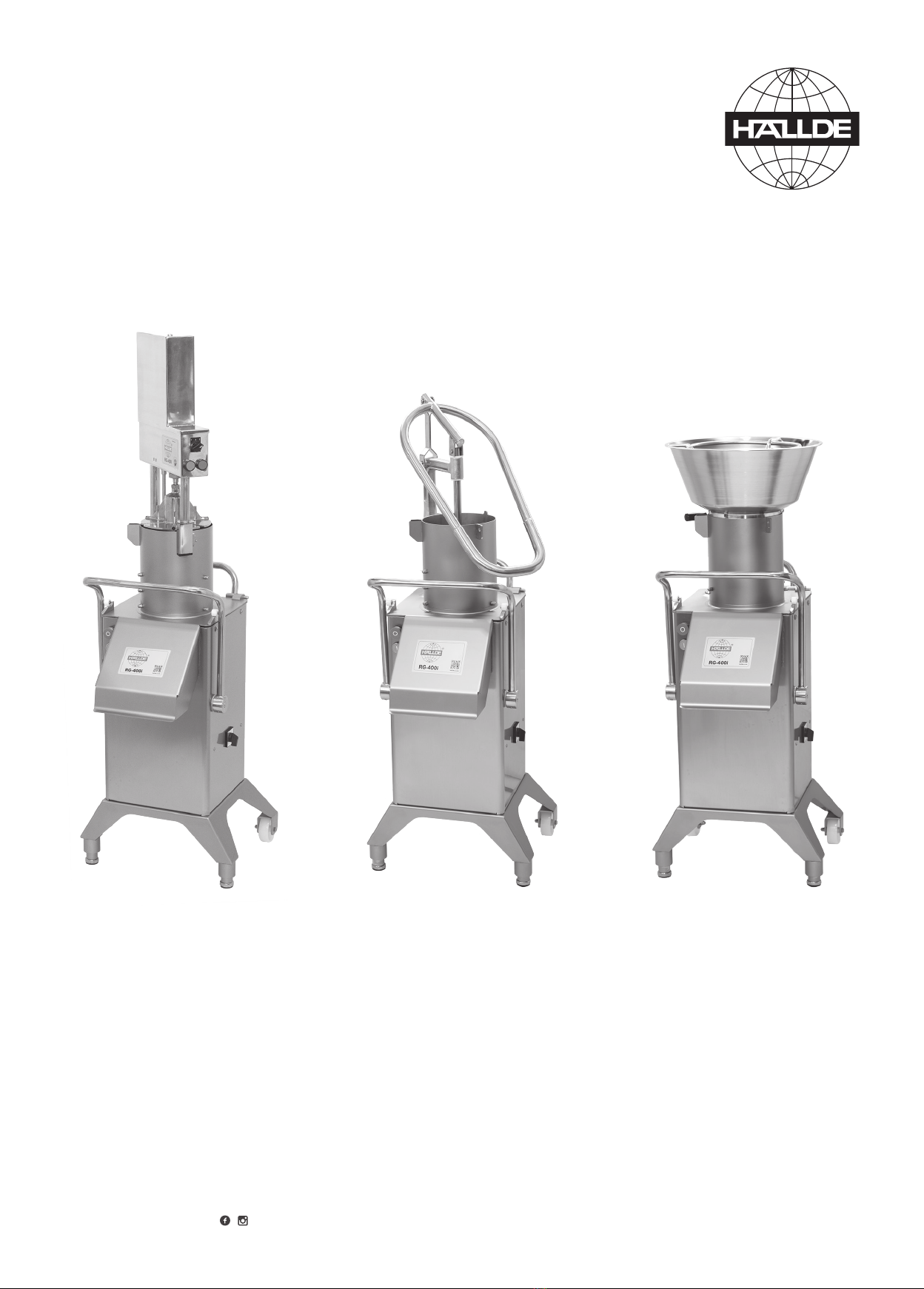
HALLDE • User Instructions
TYPE OF PROCESSING
Slices, dices, grates, shreds, cuts julienne,
crimping slices and potato chips in a variety
of dimensions, depending on the cutting tool
selected. Processes vegetables, fruit, dry
bread, cheese, nuts, mushrooms etc.
USERS
Restaurants, shop kitchens, hospitals, schools,
fast food outlets, catering, pizzerias, ships,
central kitchens, institution kitchens, food
processing industries etc.
CAPACITY
Up to 3 000 portions per day, 15 kg per minute
with the manual feeder and 40 kg per minute
with the feed hopper.
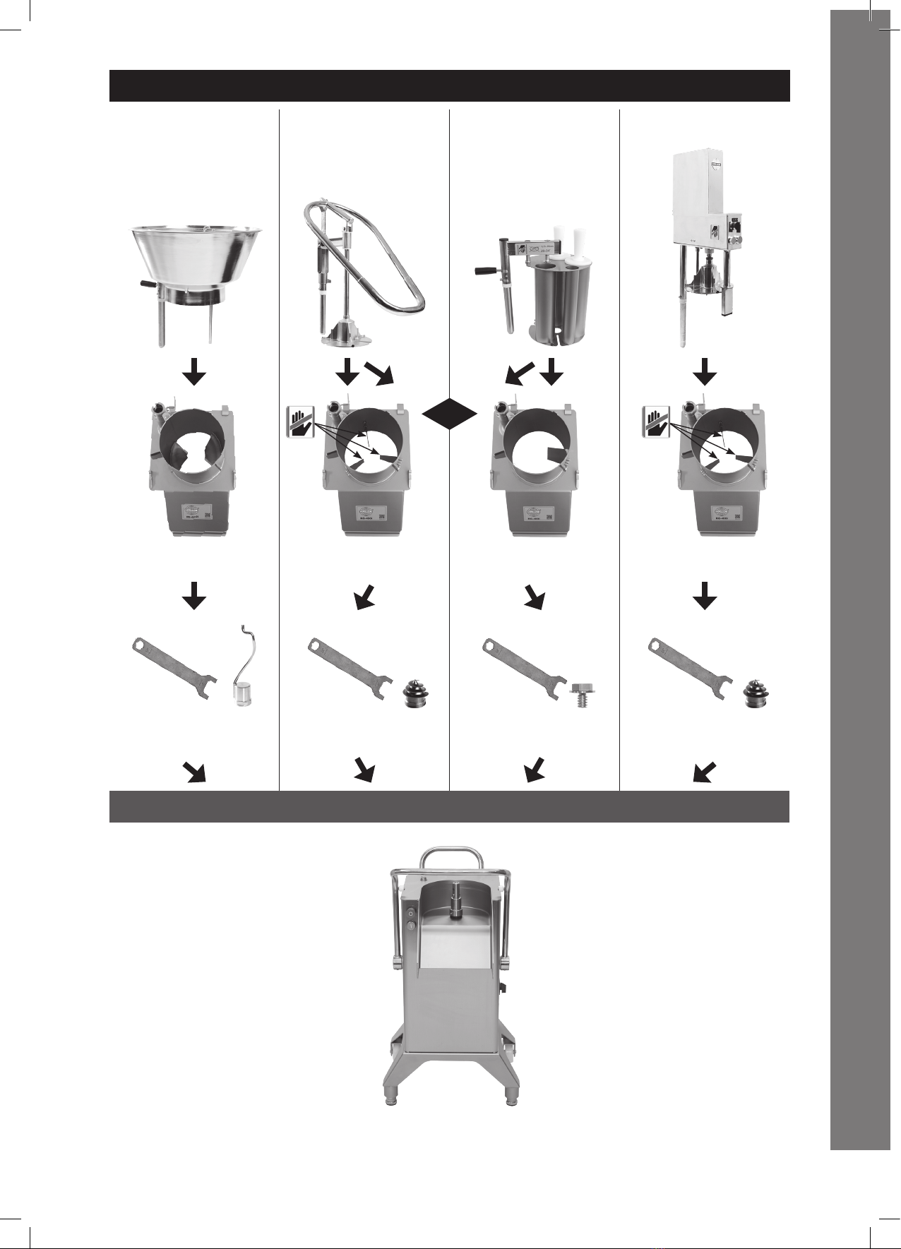
USING THE FEEDERS
MANUAL FEEDER, ERGO LOOP/
PNEUMATIC PUSH FEEDER:
These two feeders can be used for all types of
products, small and large.
Feed Cylinder A with three internal knives x
and divide up the product during preparation
and is optimized for preparation of cabbage.
MANUAL FEEDER, ERGO LOOP
Feed Cylinder B with one internal wall is
optimized for manually orienting of products,
stacking.
THE FEED HOPPER:
Is used for continuous cutting of large quantities
of round products like potatoes, onions etc.
THE 4-TUBE INSERT:
Is used for cutting long products such as
cucumbers into slicers, see picture.
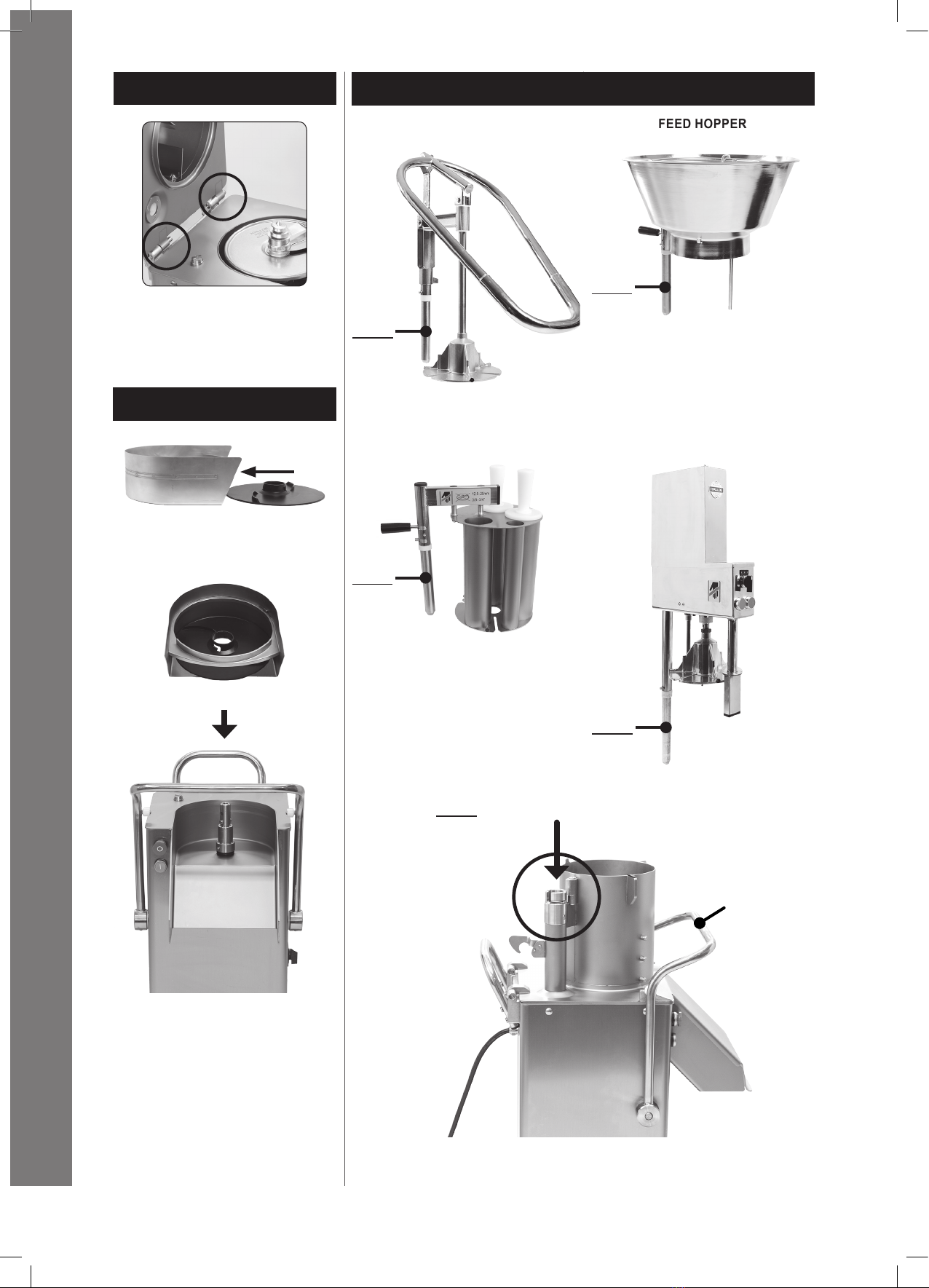
ASSEMBLING AND DISMANTLING
THE FEED CYLINDER
When tting, fold down the locking handle.
Push the feed cylinder onto the hinge pins of
the machine, and lower the feed cylinder.
Raise the locking handle.
When removing, rst remove the feed attach-
ment.
Lower the locking handle.
Remove the feed cylinder from the hinge pins
of the machine.
THE 4-TUBE INSERT
Press the stop button.
When tting, t feed cylinder A or B.
Place the 4-tube insert in the feed cylinder with
the shaft in the feed cylinder tube.
Press down the 4-tube insert and turn the
locking knob anti-clockwise.
When removing, turn the locking knob clock-
wise and remove the 4- tube insert.
THE MANUAL PUSH FEED
ATTACHMENT
Press in the machine stop button.
When tting, t feed cylinder A or B.
Move the lever up all the way.
Fit the manual push feed attachment shaft
into the feed cylinder tube.
Press down the manual push feed attachment
and swing it in anti-clockwise.
When removing, press down the stop pad and
swing out the manual push feed attachment
clockwise and remove it.
THE PNEUMATIC PUSH FEED
ATTACHMENT
Press in the machine stop button.
When tting, t feed cylinder A.
Fit the pneumatic push feed attachment shaft
into the feed cylinder tube.
Press down the pneumatic push feed
attachment and swing it anti-clockwise.
Push the compressor hose snap coupling onto
the pneumatic push feed attachment nipple.
Set the speed controls of the machine and of
the pneumatic push feed attachment to suit
the cutting tool being used as specied in the
instructions under the heading SETTING THE
SPEED CONTROLS.
Start the compressor and adjust its delivery
pressure to 5,5 bar. Handle the compressor
in accordance with the manufacturer’s
instructions.
Check the air pressure on the pressure gauge.
The recommended air pressure is 5 bar but
the actual value needed may vary. If the air
pressure reading on the pressure gauge is
different, pull the control upwards and then turn
it until the pressure gauge reading is 5 bar, and
then press it back down again.
When removing, switch off the compressor
and then disconnect the compressor hose
snap coupling from the pneumatic push feed
attachment nipple.
Press down the stop pad and swing out the
pneumatic push feed attachment clockwise,
and then remove it.
THE FEED CYLINDER FOR FEED
HOPPER
When tting, fold down the locking handle.
Push the feed cylinder onto the hinge pins of
the machine, and lower the feed cylinder.
Raise the locking handle.
When removing, rst remove the feed attach-
ment.
Lower the locking handle.
Remove the feed cylinder from the hinge pins
of the machine.
THE FEED HOPPER
Press in the stop button.
When fitting, fit the feed cylinder with two
internal guides.
Place the feed hopper in the centre of the feed
cylinder, with the shaft in the feed cylinder tube.
Press down the feed hopper and turn the
locking knob anti-clockwise.
When removing, turn the locking knob
clockwise and remove the feed hopper.
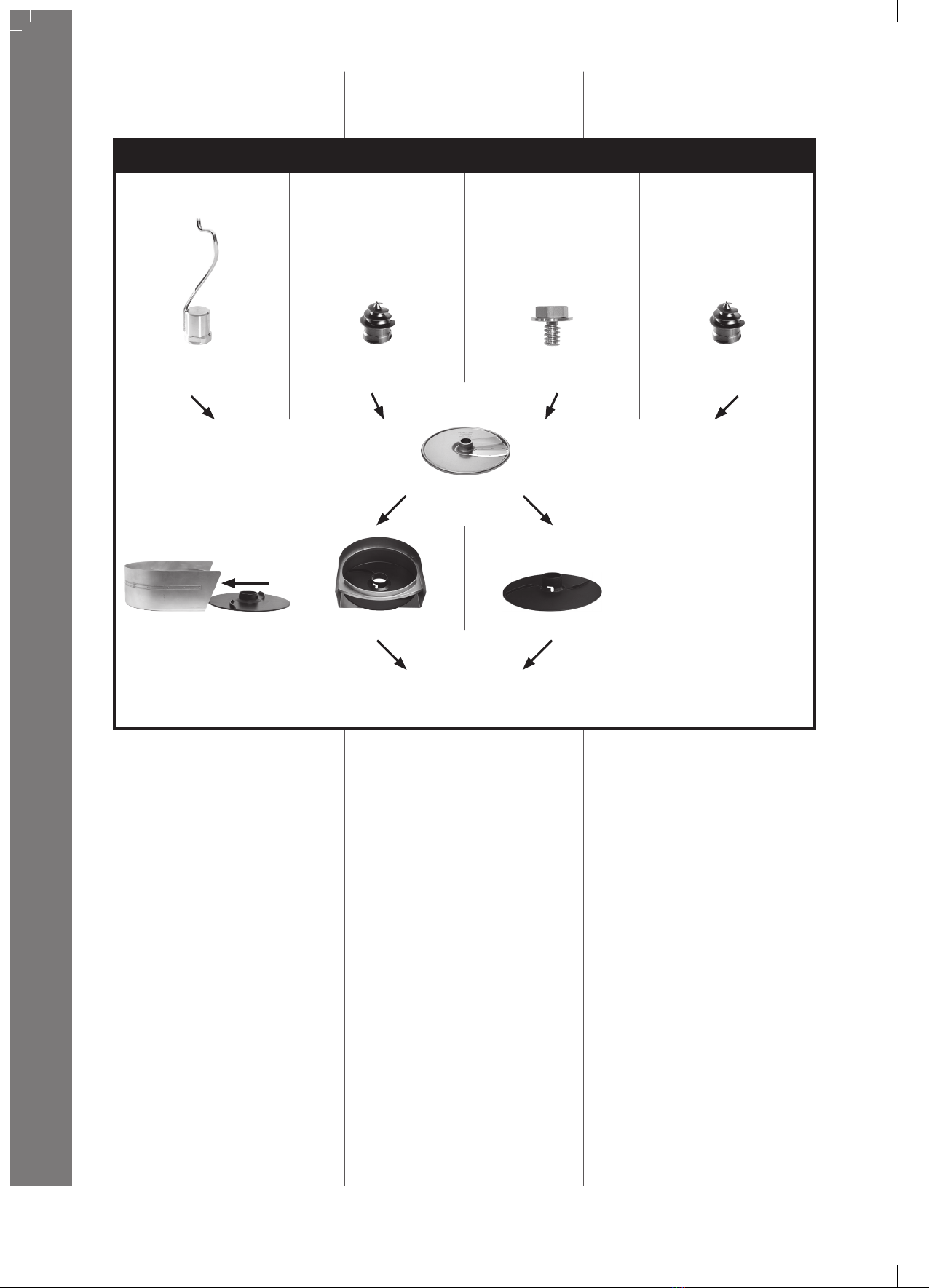
FITTING THE CUTTING TOOLS
AND TRAY
While using the manual or pneumatic feeder,
make sure the pusher plate is in the upper
position and swing it out the feeder to the left.
If the feed hopper or 4-tube insert is being
used, lift the shaft out of its mounting at the
back of the machine.
Lower the locking handle and tilt the feeder
backwards.
If the tray is to be used, the ejector plate is
placed in the bottom of the tray. Ensure that the
machine’s knife housing has been thoroughly
cleaned. The tray, containing the ejector
plate, is then mounted around the shaft of the
machine’s knife housing. Turn/push down the
ejector plate down into its coupling.
Place the chosen cutting tool on the shaft and
rotate the cutting tool so that it drops rmly
into its position.
When using Dicing Grid or French Fry Grid:
place the ejector plate in the bottom of the
tray, which is, in turn, mounted around the
shaft of the machine’s knife housing. Turn
the ejector plate down into its coupling. Then
mount the chosen grid onto the shaft followed
by the slicer, ensuring that both fall properly
into place.
Secure the agitator device when using the
feed hopper, the locking bolt when using the
4-tube insert, or the decoring device when
using the manual or the pneumatic push feed
attachment, by turning them anti-clockwise by
means of the wrench onto the centre shaft of
the cutting tool.
REMOVAL OF THE CUTTING TOOLS
AND TRAY
Unscrew the screw cap, drill sleeve or lock
bolt clockwise using the key and remove the
cutting tool/tools, and the ejector plate together
with the tray.
SETTING THE SPEED CONTROLS
The machine speed control is normally set to
position “2” for all cutting other than dicing,
when the speed control should be in position
“1”.
When cutting with the pneumatic push feed,
set the speed control of the machine and
push feed attachment in accordance with the
following table.
PF = Pneumatic push feed attachment.
M = Machine.
SLICER
0.5–1.5 mm:.........................PF = 1. M = 2.
2–3 mm:...............................PF = 2. M = 2.
4–7 mm:...............................PF = 3. M = 2.
8–14 mm:.............................PF = 3. M = 1.
15–20 mm:...........................PF = 3. M = 1.
HC SLICER
2 mm: ..................................PF = 2. M = 2.
4–6 mm:...............................PF = 3. M = 2.
8–20 mm:............................PF = 3. M = 1.