HallonPower X6-Electromod User manual

18 June 2016
X6-ElectroMod
A 160AH 1.5KW Electrical Power Generator for the BMW X6
pg. 1
Copyright © 2016, HallonPower. All content and images presented on this website are copyrighted © and all rights are reserved.
All manufacturer names, symbols, and descriptions, used in our images and text are used solely for identification purposes only. It is neither inferred nor
implied that any item sold here, is a product authorized by or in any way connected with any vehicle manufacturers displayed on this page. This document
may be modified at any time and without notice.
Installation Manual

18 June 2016
X6-ElectroMod
A 160AH 1.5KW Electrical Power Generator for the BMW X6
pg. 2
Copyright © 2016, HallonPower. All content and images presented on this website are copyrighted © and all rights are reserved.
All manufacturer names, symbols, and descriptions, used in our images and text are used solely for identification purposes only. It is neither inferred nor
implied that any item sold here, is a product authorized by or in any way connected with any vehicle manufacturers displayed on this page. This document
may be modified at any time and without notice.
Contents
System Installation..................................................................................................................................4
Prerequisites .......................................................................................................................................4
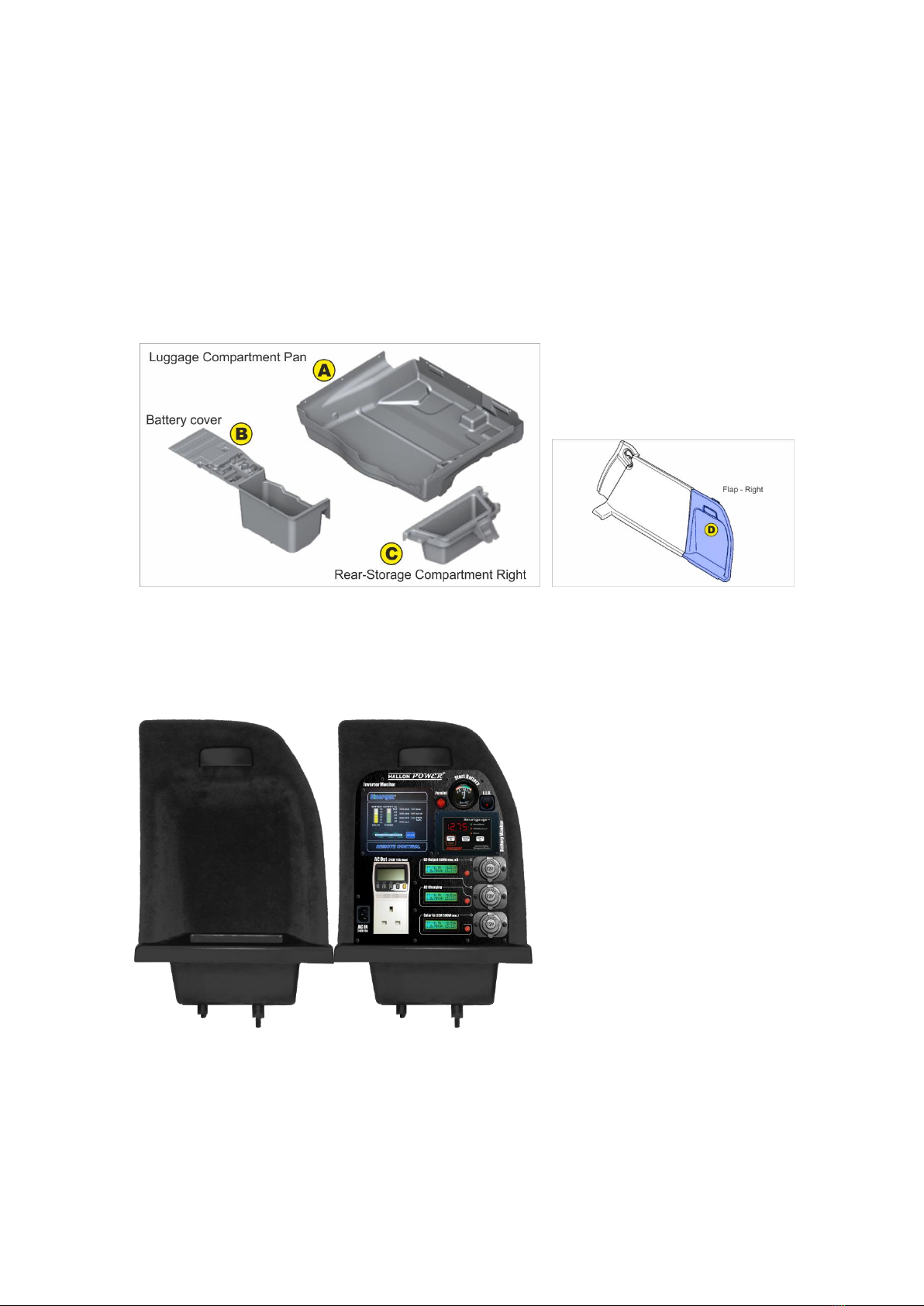
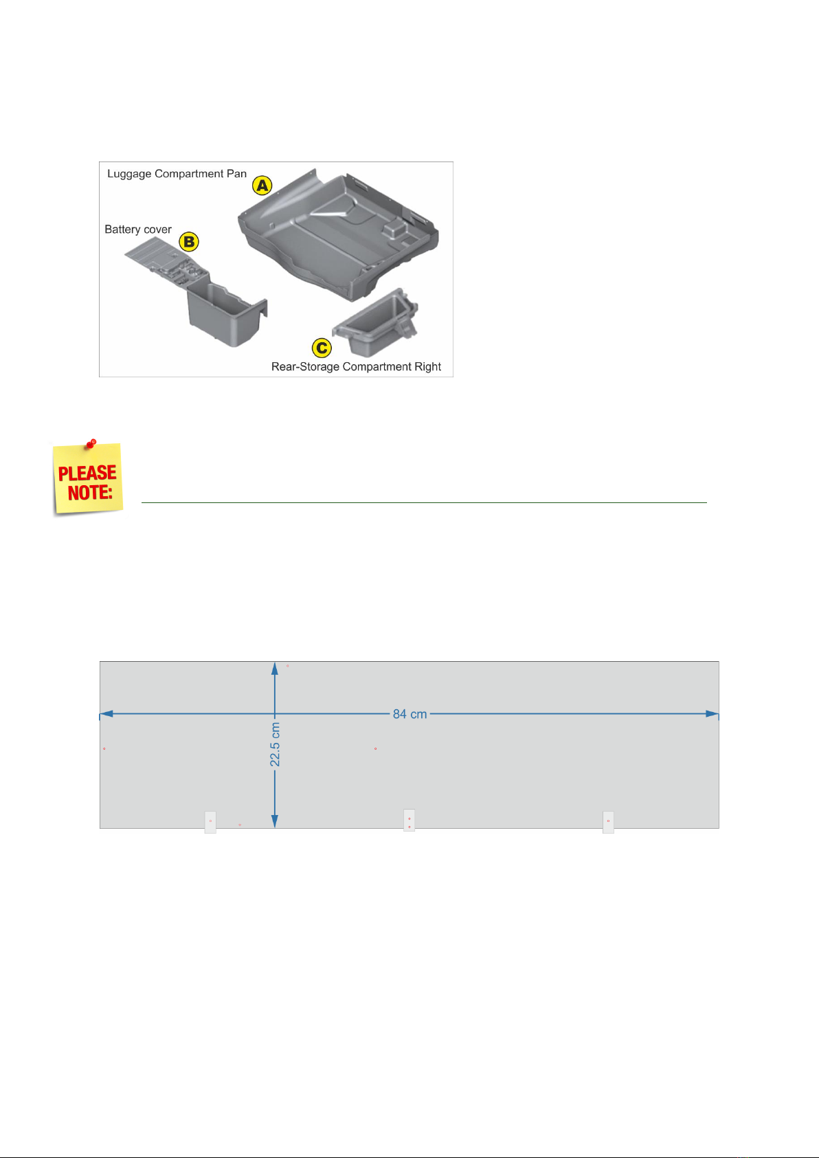
Fitting the System Panel into an BMW X6 E71 ...................................................................................5
Battery base leveling.......................................................................................................................6
System Panel Fastening onto the car body.....................................................................................6
Power Distribution Vertical Panel...................................................................................................7
Important Cable Considerations before Installation ..........................................................................8
M300 Charger cable modifications .................................................................................................8
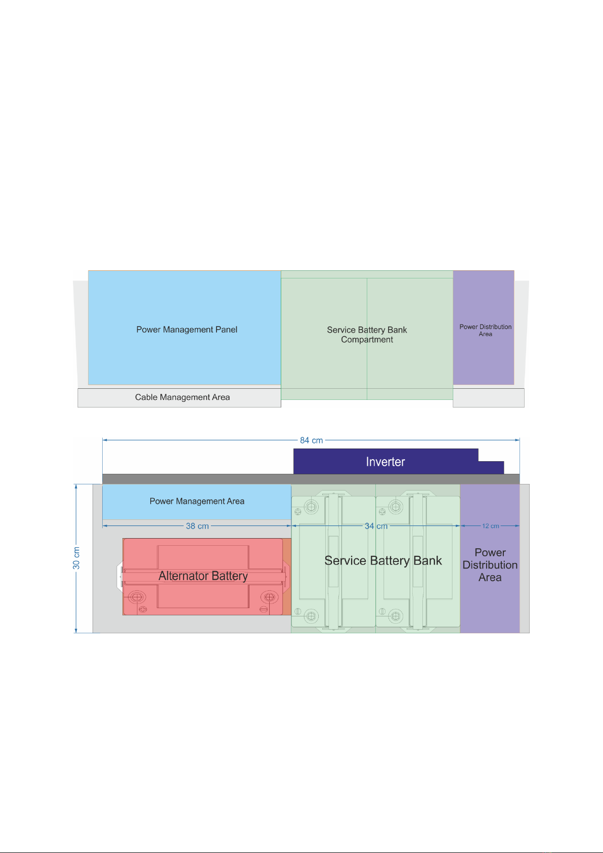
Familiarization with the System............................................................................................................10
Side view ...........................................................................................................................................10
Top-down View .................................................................................................................................10
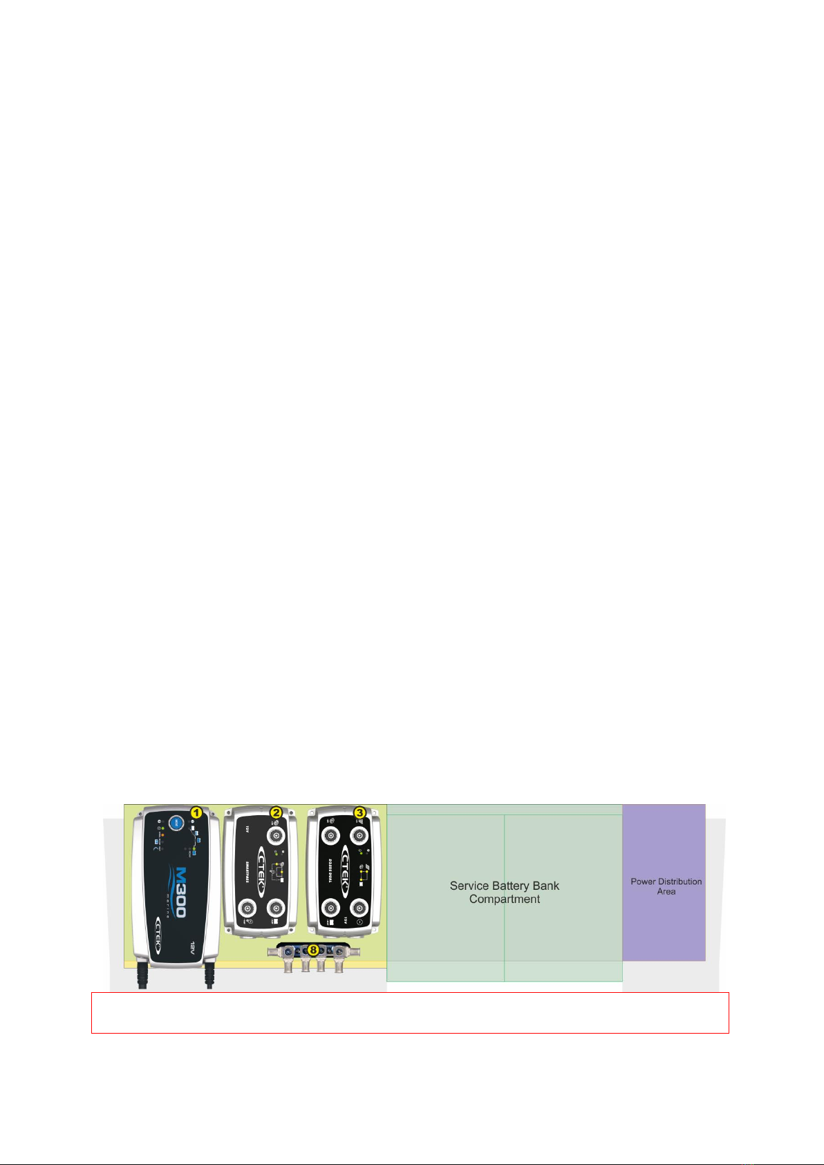
1. The Power Management Area ......................................................................................................11
Thermal Sensors............................................................................................................................12
2. The Service Battery Bank Compartment.......................................................................................12
Battery Fastening ..........................................................................................................................12
3. The Power Distribution Area.........................................................................................................13
4. The Inverter Area ..........................................................................................................................15
5. The System Control Panel (SCP)....................................................................................................18
SCP Baseplate................................................................................................................................18
Input & Output connectors of the SCP baseplate.........................................................................18
System Cable Harness ...................................................................................................................19
Notes & warnings..........................................................................................................................20
Installation procedure.......................................................................................................................21
A. System Panel (SP) .....................................................................................................................21
B. Inverter .....................................................................................................................................21
C. Cable Harness............................................................................................................................22
D. Chassis GND..............................................................................................................................22
E. Power Distribution Vertical Panel ............................................................................................. 22
F. Power Distribution Bottom Panel .............................................................................................23
G. Power Distribution Top Panel & CBs ........................................................................................24
H. The Batteries.............................................................................................................................25
I. System Control Panel (SCP)........................................................................................................26

18 June 2016
X6-ElectroMod
A 160AH 1.5KW Electrical Power Generator for the BMW X6
pg. 3
Copyright © 2016, HallonPower. All content and images presented on this website are copyrighted © and all rights are reserved.
All manufacturer names, symbols, and descriptions, used in our images and text are used solely for identification purposes only. It is neither inferred nor
implied that any item sold here, is a product authorized by or in any way connected with any vehicle manufacturers displayed on this page. This document
may be modified at any time and without notice.
Powering ON & Systems Check......................................................................................................... 27
APPENDIX A...........................................................................................................................................31
Cables & Connections .......................................................................................................................31
System Cable Harness Details (see also Table of Connections 22-39)............................................. 32
Table of Connections ........................................................................................................................33
Connections by Type.........................................................................................................................35
Cable List ...........................................................................................................................................39

18 June 2016
X6-ElectroMod
A 160AH 1.5KW Electrical Power Generator for the BMW X6
pg. 4
Copyright © 2016, HallonPower. All content and images presented on this website are copyrighted © and all rights are reserved.
All manufacturer names, symbols, and descriptions, used in our images and text are used solely for identification purposes only. It is neither inferred nor
implied that any item sold here, is a product authorized by or in any way connected with any vehicle manufacturers displayed on this page. This document
may be modified at any time and without notice.
System Installation
Prerequisites
A. Prepare the car:
Before fitting the System Panel in the car,
1. The Luggage Compartment Pan (A) (part no. 51476981061) and the Battery Cover (B) (part
no. 51476981050) will have to be removed to make room for the installation.
2. The X6 Interior-Rear-Storage Compartment Right (C) (part no. 51476981048) sits right
underneath the Right Flap (D). An 8cm hole will need to be opened on the front side of this
Storage Compartment, large enough for the connecting Powerpole plugs to pass through it.
B. Prepare the PM panel (see The Power Management Area):
The Power Management Panel houses 3 components from CTEK and a Grounding Bus Bar (GBB).
CTEK M300 charger #1.
CTEK Smartpass #2.
CTEK D250S Dual #3.
Grounding Bus Bar #8 (GBB).
1. Attach all the PM components (D250S, Smartpass, M300 and Grounding Bus Bar).
2. Now connect all cables to each PM component (LOOM1 & LOOM2) (see Appendix A).
D. Prepare the SP by making sure:
1. All 3 base brackets are attached and
2. Both side brackets are not attached so as not to interfere with the installation (we will add
them later on).
3. The 2 bottom Inverter screws are screwed onto the SP to allow easy Inverter fastening.
4. Attach the PM panel to the SP and
5. Take the SP & the 3 other panels to the car for installation (see Installation procedure).
CAUTION: Please arrange for adequate protection of your rear bumper during installation to protect
it from scratches.

18 June 2016
X6-ElectroMod
A 160AH 1.5KW Electrical Power Generator for the BMW X6
pg. 5
Copyright © 2016, HallonPower. All content and images presented on this website are copyrighted © and all rights are reserved.
All manufacturer names, symbols, and descriptions, used in our images and text are used solely for identification purposes only. It is neither inferred nor
implied that any item sold here, is a product authorized by or in any way connected with any vehicle manufacturers displayed on this page. This document
may be modified at any time and without notice.
Fitting the System Panel into an BMW X6 E71
The solution is housed on a single plywood panel that fits snugly and discretely underneath the
trunk floor in the luggage compartment of your BMW X6 (also called the Trunk Floor
Compartment).
Before fitting the System Panel, the Luggage Compartment Pan (A) (part no. 51476981061) and
the Battery Cover (B) (part no. 51476981050) will have to be removed to make room for the
installation. These parts are found
under the trunk floor. Place these
items in storage as they will no
longer be needed.
A System Control Panel (SCP) is also included in the solution which is housed on the right hand
side of the trunk of the BMW X6, also discretely and seamlessly blended into the Right Flap (D)
found in the trunk.
The X6 Interior-Rear-Storage
Compartment Right (C) (part no.
51476981048) sits right underneath
the Right Flap (D). All wiring from the
Trunk Floor Luggage Compartment,
where the solution is installed, will
have to pass through this Storage
Compartment (C) in order to connect
to the SCP (see section about the
System Control Panel).
For this reason a hole will need to be
opened on the front side of the
Storage Compartment (C), large
enough (about 8cm) for the connecting Powerpole plugs to pass through (the hole will be out of
sight, hidden below the trunk floor level and completely covered by the SCP which will be sitting
over it).

18 June 2016
X6-ElectroMod
A 160AH 1.5KW Electrical Power Generator for the BMW X6
pg. 6
Copyright © 2016, HallonPower. All content and images presented on this website are copyrighted © and all rights are reserved.
All manufacturer names, symbols, and descriptions, used in our images and text are used solely for identification purposes only. It is neither inferred nor
implied that any item sold here, is a product authorized by or in any way connected with any vehicle manufacturers displayed on this page. This document
may be modified at any time and without notice.
Battery base leveling
After removing the Battery Cover (B)
from the luggage compartment below
the trunk floor of the X6, you will notice
that the floor is quite uneven.
For this reason a suitable floor leveling
material will be required in order for the
batteries to sit level.
You could try using several small pieces
of fitted carpeting, layered on top of
each other to fill in the gaps and grooves. Finally, once you have established a level base, you can
top it off with a single larger piece of carpeting to form the base where the batteries will sit.
Do not make this base too thick otherwise you may have trouble closing the trunk
floor after you install the batteries.
System Panel Fastening onto the car body
The System Panel is attached to the base of the trunk of the X6 by 3 L-shaped brackets that slot into
existing floor grooves.
These are not meant to fasten the panel in position with screws but are rather meant to restrict its
movements both vertically and horizontally, keeping it aligned and steady.

18 June 2016
X6-ElectroMod
A 160AH 1.5KW Electrical Power Generator for the BMW X6
pg. 7
Copyright © 2016, HallonPower. All content and images presented on this website are copyrighted © and all rights are reserved.
All manufacturer names, symbols, and descriptions, used in our images and text are used solely for identification purposes only. It is neither inferred nor
implied that any item sold here, is a product authorized by or in any way connected with any vehicle manufacturers displayed on this page. This document
may be modified at any time and without notice.
Two side brackets are actually screwed onto the sides of the trunk. These are actually what really
hold the System Panel in position. So once you lower the panel into the luggage compartment, slide
the 3 bottom brackets all the way into the floor slots.
Wait until the Power Distribution Vertical Panel has been placed into position and then using two
screws, fasten these side brackets onto the sides of the trunk.
Power Distribution Vertical Panel
This panel separates the Power Distribution area from the Service Battery Bank compartment. It is
used to fasten the PD area components and helps
to keep the batteries in place.
It will require a screw to hold it in position against
the rear wall of the trunk floor compartment.
Please follow the detailed installation instructions
in the ‘Installation procedure’ section.
There are a total of 3 screws that will ever be drilled into any part of the car in this
solution. We tried to keep any invasive means to an absolute minimum. This is why
we have employed the L-shaped brackets to provide us with the necessary stability
without using any screws, which also makes removing the panel a breeze.

18 June 2016
X6-ElectroMod
A 160AH 1.5KW Electrical Power Generator for the BMW X6
pg. 8
Copyright © 2016, HallonPower. All content and images presented on this website are copyrighted © and all rights are reserved.
All manufacturer names, symbols, and descriptions, used in our images and text are used solely for identification purposes only. It is neither inferred nor
implied that any item sold here, is a product authorized by or in any way connected with any vehicle manufacturers displayed on this page. This document
may be modified at any time and without notice.
Important Cable Considerations before Installation
M300 Charger cable modifications
Both the AC cable of the charger and the DC out cables have to be modified to connect to the rest of
the system.
1. The M300 AC cable must have a
plug change. Allow enough cable
to be able to reach the SCP.
Remove the mains plug from the
cable and replace it with a C14
plug as shown. This will be able to
connect to the bottom of the SCP
and receive AC current from
there.
2. The M300 DC Out cable needs to
also have its plug changed (not
shown here). Allow enough
cable to be able to reach the
SCP. Remove the DC plug from
the cable and replace it with 2x
Anderson Powerpoles. Make
sure the positive red cable is
fitted with a red Powerpole and
the negative black cable is fitted
with a black Powerpole. These will be able to connect to the colour matching Powerpoles on a
long cable coming out of LOOM 2 (shown above).
When connecting the M300 Powerpoles to the LOOM2 matching Powerpoles,
zip-tie them together so that they do not get disconnected during installation.
If you find that the M300 is not charging your batteries, it is probably because these
connectors were disconnected. To avoid the inconvenience of removing cables and
batteries to get to this joint, make sure you tie them up pretty well!
WARNING!
Connect the M300 only to LOOM2 colour matching Powerpoles (red&black)!
Do not connect to loom1 Powerpoles (white&black) which are designed to output DC
current. Connecting here may damage your charger.

18 June 2016
X6-ElectroMod
A 160AH 1.5KW Electrical Power Generator for the BMW X6
pg. 9
Copyright © 2016, HallonPower. All content and images presented on this website are copyrighted © and all rights are reserved.
All manufacturer names, symbols, and descriptions, used in our images and text are used solely for identification purposes only. It is neither inferred nor
implied that any item sold here, is a product authorized by or in any way connected with any vehicle manufacturers displayed on this page. This document
may be modified at any time and without notice.
3. The D250/AB-M300/P cable (shown in yellow) has to be soldered directly onto the DC +ve
output cable of the M300 charger (shown red), at the point where it passes right below the
D250S module. The M300 +ve cable must not be severed here.
Instead it must just be striped locally to allow the soldering of the 2 cables to take place. Please
insulate the joint properly.
The rest of the cable is allowed to continue until it attaches to the System Control Panel via the 2
Anderson Powerpoles mentioned above.
The rest of cabling should be done in accordance with Appendix A and specifically with the
help of ‘Table of Connections’ or ‘Connections by Type’.
Do not be intimidated by the long listings. There are actually only 21 single cables that must
be connected and another 10 connections involving the SCP baseplate and the LOOMs.
You will find particularly useful the ‘Connections by Type’ table, since it lists each module and
every connection going to it.
The next section will walk you through the whole process

18 June 2016
X6-ElectroMod
A 160AH 1.5KW Electrical Power Generator for the BMW X6
pg. 10
Copyright © 2016, HallonPower. All content and images presented on this website are copyrighted © and all rights are reserved.
All manufacturer names, symbols, and descriptions, used in our images and text are used solely for identification purposes only. It is neither inferred nor
implied that any item sold here, is a product authorized by or in any way connected with any vehicle manufacturers displayed on this page. This document
may be modified at any time and without notice.
Familiarization with the System
The solution is split into 6 main sections.
1. The Power Management Area that houses the Power Management Panel.
2. The Service Battery Bank Compartment.
3. The Power Distribution Area.
4. The Inverter Area (on the rear of the System Panel - not shown above).
5. The System Control Panel (SCP) (not shown below).
6. The Cable Management Area (for wiring see Appendix A).
Side view
Top-down View

18 June 2016
X6-ElectroMod
A 160AH 1.5KW Electrical Power Generator for the BMW X6
pg. 11
Copyright © 2016, HallonPower. All content and images presented on this website are copyrighted © and all rights are reserved.
All manufacturer names, symbols, and descriptions, used in our images and text are used solely for identification purposes only. It is neither inferred nor
implied that any item sold here, is a product authorized by or in any way connected with any vehicle manufacturers displayed on this page. This document
may be modified at any time and without notice.
1. The Power Management Area
The Power Management Panel houses 3 components from CTEK and a Grounding Bus Bar (GBB).
1. CTEK M300 charger #1.
2. CTEK Smartpass #2.
3. CTEK D250S Dual #3.
4. Grounding Bus Bar #8 (GBB).
Each component has to be screwed into place on the Power Management Area Panel.
Once this is done, the Power Management Area Panel in turn should be taken and fastened onto the
front of the System Panel using the four
fastening holes provided on the System Panel.
All wires should be fastened securely and
threaded to their relevant destination
according to the wiring diagram (see wiring
section). When finished, it should look
something like this.

18 June 2016
X6-ElectroMod
A 160AH 1.5KW Electrical Power Generator for the BMW X6
pg. 12
Copyright © 2016, HallonPower. All content and images presented on this website are copyrighted © and all rights are reserved.
All manufacturer names, symbols, and descriptions, used in our images and text are used solely for identification purposes only. It is neither inferred nor
implied that any item sold here, is a product authorized by or in any way connected with any vehicle manufacturers displayed on this page. This document
may be modified at any time and without notice.
Thermal Sensors
The M300, Smartpass and D250S each come with a thermal sensor cable (#10) attached to the
device. These should be attached on the top surface of one of the batteries in the Service Battery
Bank, preferably near the positive pole.
2. The Service Battery Bank Compartment
The area houses the Service Battery Bank.
If choosing your own batteries, please make sure the model you choose will be smaller than the
space specified below. Between 1 or 2 large capacity batteries can fit in this space, depending on
their dimensions and protrusions.
WARNING!
Both batteries must fit in this space: Length 11.13in (283mm) x Width 13.2in (336mm) x
Height 9.25in (235mm). Not even a millimetre larger! You may have to remove the battery
holding straps after inserting the batteries into the Service Battery Bank compartment.
Store these in a safe place for when you will need to replace the batteries or in case you
may need to service the system.
Battery Fastening
On the left side of the Service Battery Bank, we have the main Alternator Battery and on the right
side, the Power Distribution Vertical Panel holding the batteries from moving in either direction. If
required, a battery fastener can be used to hold the batteries down onto the trunk floor. In our case
we found that this is not necessary.

18 June 2016
X6-ElectroMod
A 160AH 1.5KW Electrical Power Generator for the BMW X6
pg. 13
Copyright © 2016, HallonPower. All content and images presented on this website are copyrighted © and all rights are reserved.
All manufacturer names, symbols, and descriptions, used in our images and text are used solely for identification purposes only. It is neither inferred nor
implied that any item sold here, is a product authorized by or in any way connected with any vehicle manufacturers displayed on this page. This document
may be modified at any time and without notice.
3. The Power Distribution Area
This hosts 4 CBs and a motorized switch (BEP 701MD).
The BEP 701-MD’s main functionality is to provide a ‘Parallel Battery Mode’ for the system.
WARNING!
For normal system operation, make sure that Parallel Mode is OFF.
Engage Parallel Mode only in emergencies,
when the Alternator Battery cannot start the engine.
The BEP 701-MD’s secondary functionality is to of course distribute power to the system, via the
CBs. As we have already seen, the switch is connected directly to each battery bank.
From here various cables connect to CB#4, CB#5 and CB#7 which are responsible for protecting,
switching and distributing power over those lines.

18 June 2016
X6-ElectroMod
A 160AH 1.5KW Electrical Power Generator for the BMW X6
pg. 14
Copyright © 2016, HallonPower. All content and images presented on this website are copyrighted © and all rights are reserved.
All manufacturer names, symbols, and descriptions, used in our images and text are used solely for identification purposes only. It is neither inferred nor
implied that any item sold here, is a product authorized by or in any way connected with any vehicle manufacturers displayed on this page. This document
may be modified at any time and without notice.
All power flowing to each part of the system passes through this switch,
up to 275A continuous (see ‘Wiring’ section for more information).
CB#4 feed the Smartpass with power from each battery bank. CB#4
feeds power from the Alternator Battery, while CB#5 feeds power from
the Service Battery Bank (see ‘Wiring’ section for details). The power
cables feeding these CBs come from the BEP-701MD switch directly,
which is capable of either delivering the power separate or after bridging
the battery banks (parallel mode).
CB#4, rated at 150A, protect the D250S & Smartpass according to
the manufacturer’s guidelines, instead of a 150A fuse, meanwhile
providing a way for the user to easily switch these modules ON or OFF.
CB#6, rated at 50A, is used to protect the Non-Critical Consumers 12V DC
output of the Smartpass as well as providing a way for the user to easily
switch this output ON or OFF.
Finally CB#7, rated at 200A, is responsible for feeding power into the
SINERGEX Puresine2 1500W Inverter, while at the same time protecting the
unit according to the manufacturer’s guidelines, in place of a 200A fuse.
CB#7 also provides a convenient way to switch the inverter ON and OFF
without having to fiddle around to find its 3-way switch behind the System
Panel. It is recommended to place this switch in the II position at
installation, which places the inverter in remote control mode. Thus when
CB#7 is also switched to the ON position, the inverter can easily be turned ON or OFF directly from
the SCP.
It is recommended to place CB#7 to the OFF position when you no longer require
use of the inverter to avoid anybody turning it on or even leaving it on accidentally.

18 June 2016
X6-ElectroMod
A 160AH 1.5KW Electrical Power Generator for the BMW X6
pg. 15
Copyright © 2016, HallonPower. All content and images presented on this website are copyrighted © and all rights are reserved.
All manufacturer names, symbols, and descriptions, used in our images and text are used solely for identification purposes only. It is neither inferred nor
implied that any item sold here, is a product authorized by or in any way connected with any vehicle manufacturers displayed on this page. This document
may be modified at any time and without notice.
4. The Inverter Area
The System Panel also houses a Power Inverter, installed on its rear side, for the generation of 240V
AC power on the go.
WARNING!
Whatever inverter you may choose, the most important consideration is its width which
must be less than 22cm otherwise it will not fit on the back of the System Panel. Its length
and height can be anything you want.
WARNING!
The second most important consideration is that its continuous power output does not
exceed 3000W. The system is designed to handle continuous currents of up to 275A (limited
only by the bridging switch) to any Inverter and therefore a 3KW device would be the limit.
The other important consideration is the remote control unit. This has to be able to
fit in the slot on the System Control Panel. The slot has a hole of 96mm x 86mm and
was designed for remote controls of 130mm x 120mm dimensions.
Of course any other remote can be fitted, but you would have to cut a custom size
hole on a 130mmx120mm aluminium cover which we can provide.
Every possible measure has been taken to ensure that the positioning of the inverter
follows the manufacturer’s guidelines. Placing the inverter on the reverse side of the
System Panel separates it from any contact with the batteries. Make sure you
adhere to these guidelines while in operation.
ON / OFF/ REMOTE (Main) switch:
a. Before installing the inverter, make sure the main switch must be “OFF”.
b. Before using the remote unit, make sure the main switch must be “REMOTE”.

18 June 2016
X6-ElectroMod
A 160AH 1.5KW Electrical Power Generator for the BMW X6
pg. 16
Copyright © 2016, HallonPower. All content and images presented on this website are copyrighted © and all rights are reserved.
All manufacturer names, symbols, and descriptions, used in our images and text are used solely for identification purposes only. It is neither inferred nor
implied that any item sold here, is a product authorized by or in any way connected with any vehicle manufacturers displayed on this page. This document
may be modified at any time and without notice.
Installation:
Where to install:
The power inverter should be installed in a location that meets the following requirements:
Dry –Do not allow water to drip or splash on the inverter.
Cool –Ambient air temperature should be between 0 and 40 , the cooler the better.
Safe –Do not install in a battery compartment or other areas where flammable fumes may
exist, such as fuel storage areas or engine compartments.
Ventilated –Allow at least one inch of clearance around the inverter for air flow. Ensure the
ventilation openings on the rear and front of the unit are not obstructed.
Dust –Do not install the Inverter in a dusty environments where are dust, wood particles or
other filings/shavings are present. This dust can be pulled into the unit when the cooling fan
is operating.
Avoid excessive cable lengths but do not install the Inverter in the same compartment as
batteries.
Use the recommended wire lengths and sizes (see section 3-5). Also do not mount the
Inverter where it will be exposed to the gases produced by the battery. These gases are very
corrosive and prolonged exposure also will damage the Inverter.
DC Input Terminals
Model
DC Input Voltage
12 V
Minimum
Maximum
10.5
15
WARNING!
Connect to 12V battery ONLY! (+) is positive, (-) is negative.
WARNING!
Reverse polarity connection will blow internal fuse and may damage inverter permanently.
WARNING! Shock Hazard.
Before proceeding further, carefully check that the Inverter is NOT connected to any
batteries, and that all wiring is disconnected from any electrical sources. Do not connect
the output terminals of the Inverter to an incoming AC source.
The X6-Electrmod bests the manufacturer recommendations for wiring and our
solution provides a 200A CB in place of the 200A fuse recommended.

18 June 2016
X6-ElectroMod
A 160AH 1.5KW Electrical Power Generator for the BMW X6
pg. 17
Copyright © 2016, HallonPower. All content and images presented on this website are copyrighted © and all rights are reserved.
All manufacturer names, symbols, and descriptions, used in our images and text are used solely for identification purposes only. It is neither inferred nor
implied that any item sold here, is a product authorized by or in any way connected with any vehicle manufacturers displayed on this page. This document
may be modified at any time and without notice.
Connect the cables to the power input terminals on the rear panel of the inverter.The red terminal is
positive (+) and black terminal is negative (-).
Insert the cables into the terminals and tighten screw
to clamp the wires securely.
WARNING!
Make sure all the DC connections are tight (torque to 9 –10 ft-lbs, 11.7 –13 Nm). Loose
connections could result overheat in a potential hazard.
Battery to inverter cable
connection
Do not place anything between battery cable lug and terminal surface. Assemble exactly as shown.
AC Safety Grounding:
The AC output ground wire should go to the grounding point for your loads
(for example, a distribution panel ground bus).
This is taken care of internally in the SCP.
What we have included here are some of the most important points regarding the
installation and operation of this inverter, making it relevant to this manual.
Please consult the Inverter user manual for more details and information.

18 June 2016
X6-ElectroMod
A 160AH 1.5KW Electrical Power Generator for the BMW X6
pg. 18
Copyright © 2016, HallonPower. All content and images presented on this website are copyrighted © and all rights are reserved.
All manufacturer names, symbols, and descriptions, used in our images and text are used solely for identification purposes only. It is neither inferred nor
implied that any item sold here, is a product authorized by or in any way connected with any vehicle manufacturers displayed on this page. This document
may be modified at any time and without notice.
5. The System Control Panel (SCP)
The SCP is installed in the right trunk flap of the X6 and makes use of the
depression in the flap to house its various components.
SCP Baseplate
Input & Output connectors of the SCP baseplate
External View

18 June 2016
X6-ElectroMod
A 160AH 1.5KW Electrical Power Generator for the BMW X6
pg. 19
Copyright © 2016, HallonPower. All content and images presented on this website are copyrighted © and all rights are reserved.
All manufacturer names, symbols, and descriptions, used in our images and text are used solely for identification purposes only. It is neither inferred nor
implied that any item sold here, is a product authorized by or in any way connected with any vehicle manufacturers displayed on this page. This document
may be modified at any time and without notice.
System Cable Harness
The SCP is making use of Anderson Powerpole connectors for their ease of use, rigidity, flexibility
and high current capability of 30A or 45A.
The cable harness comprises of 3 plugs and terminates onto the baseplate of the SCP.
1. Anderson Powepole 8x pole plug (LOOM1).
2. Anderson Powepole 4x pole plug (LOOM2).
3. C14 male plug (M300 AC plug replacement).
Cable Loom #1
Cable Loom #2
Cable Loom for the Powerpole#1 socket on the
System Control Panel...
Cable Loom for the Powerpole#2 socket on
the System Control Panel...
Additionally you should have the following:
1. Cable with 3 wires onto 1x WAGO plug (coming out of LOOM1)
2. Cable with 2 wires onto 2x Powerpoles (white&black)
(out of LOOM1 - DC Out for internal devices)
3. Cable with 2 wires onto 2x Powerpoles (red&black)
(out of LOOM2 –connects to DC Out of M300 charger)
The M300 charger has to have its DC output plugs replaced with 2x Anderson
Powerpoles in order to connect to LOOM2 (#1 & #2 on baseplate).
The 3 wires on LOOM1 (#4 red/green/black on baseplate) are coming from the
BEP 701-MD switch and connect to LOOM1 with a WAGO plug.
The -ve ground cable on LOOM2 (#3 on baseplate,#6 right) is taking up 2
Powerpole slots.

18 June 2016
X6-ElectroMod
A 160AH 1.5KW Electrical Power Generator for the BMW X6
pg. 20
Copyright © 2016, HallonPower. All content and images presented on this website are copyrighted © and all rights are reserved.
All manufacturer names, symbols, and descriptions, used in our images and text are used solely for identification purposes only. It is neither inferred nor
implied that any item sold here, is a product authorized by or in any way connected with any vehicle manufacturers displayed on this page. This document
may be modified at any time and without notice.
Notes & warnings
1. 12V DC OUT (#7) can sustain 80A from the CTEK SMARTPASS module. However this output is
limited to 50A continuous (and 100A intermittent) by the LCD Power Meters/Analyzers and
further limited down to a rating of 15A (even with the engine off) by each of the 2 DC out
receptacles on the SCP faceplate.
Therefore the maximum amp rating for this line should be 2x15A=30A max, for a maximum
power rating of 12x30A=360W continuous for both outputs (180W max each).
WARNING!
Do NOT connect devices exceeding 180W on any of the 2 DC receptacles.
This will probably damage the receptacles. If you require additional DC power, you can use
the interior Anderson plugs (see below).
2. DC OUT metered (#6) is essentially another DC socket in Anderson connector format, in
addition to the 2 already found on the face of the SCP.
This allows easy and continuous access (even with the engine off) to DC power from
anywhere inside the luggage compartment underneath the trunk floor of your car (such as
LED lights to light up the luggage compartment).
Anderson plugs have a 45A rating therefore the 12V DC OUT line is protected by a 50A CB
(CB#6) for a maximum output of 600W.
3. 12V SOLAR IN (#5) is limited to 50A continuous by the LCD Power Meters/Analyzers and to a
maximum of 23V and/or 300W by the CTEK D250S. The CTEK D250S can protect itself from
over current situations, but its manual warns about the solar panel voltage.
WARNING!
Do NOT connect 2 panels in series.
Do not exceed 23V input. Do not exceed 300W input.
4. AC Input (#10) is powering the CTEK M300 300W AC charger. This input is protected with a
10A 240V fuse in the UK plug on the charging cable that connects to the SCP faceplate.
The ‘AC Charging’ Digital LCD Power Meter/Analyzer is metering the charger’s DC
output (#1) into the battery bank and not its own AC input.
5. AC OUT (#11) is using the SINERGEX Puresine2 1500W Inverter. The Inverter is quite capable
of dealing with all extreme scenarios. Even so, this output is protected with a 10A 240V fuse
in the UK plug on the cable that connects to the inverter. Equipment drawing in excess of
10A@240V AC are not recommended as they will be stressing the Inverter and the system in
general and subsequently blowing this fuse.
Table of contents