halstrup-walcher P29 User manual

P29 Instruction Manual
Differential Pressure Transducer
for Flammable Gases
halstrup - walcher GmbH
Stegener Straße 10
D-79199 Kirchzarten
Phone:+49 (0) 76 61/39 63–0
Fax: +49 (0) 76 61/39 63–99
Internet: www.halstrup-walcher.com
Document 7100.004324 Version 1.0 04/2010

P29 Instruction Manual
2
Table of Contents:
1 Purpose of instruction manual...............................................................................................4
2 Safety precautions.................................................................................................................5
2.1 Safety concept.................................................................................................................5
2.2 Appropriate use................................................................................................................5
2.3 Shipping, assembly, electrical connections and startup...................................................5
2.4 Troubleshooting, maintenance, repairs, disposal.............................................................5
2.5 Symbols ...........................................................................................................................6
3 Start-up, maintenance, shipping............................................................................................7
3.1 Start-up............................................................................................................................7
3.2 Maintenance, repair.........................................................................................................8
3.3 Shipping...........................................................................................................................8
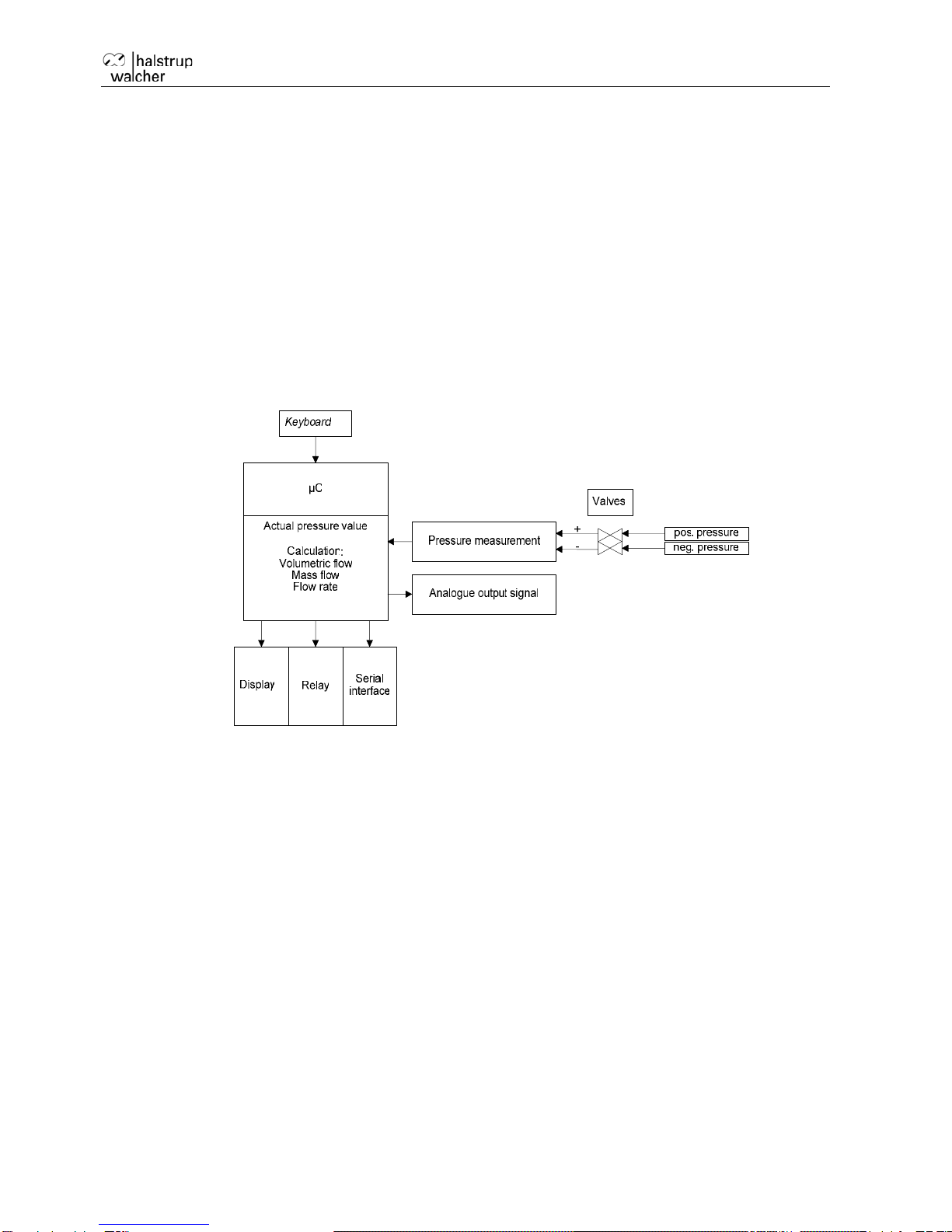
4 Instrument description...........................................................................................................9
4.1 Features...........................................................................................................................9
4.2 User interfaces...............................................................................................................10
4.3 Internal ports and keys...................................................................................................10
4.4 Front view ......................................................................................................................12
5 Zero-point calibration cycle .................................................................................................12
6 Overpressure protection......................................................................................................13
7 Display (optional).................................................................................................................13
8 Menu (optional) ...................................................................................................................13
8.1 Display...........................................................................................................................13
8.2 Scaling...........................................................................................................................14
8.2.1 Pressure ...................................................................................................................14
8.2.1.1 Top.................................................................................................................14
8.2.1.2 Bottom ...........................................................................................................14
8.2.1.3 Unit ................................................................................................................14
8.2.2 Volumetric flow .........................................................................................................14
8.2.2.1 Value..............................................................................................................15
8.2.2.2 Unit ................................................................................................................15
8.2.3 Mass flow..................................................................................................................15
8.2.3.1 Value..............................................................................................................15
8.2.3.2 Unit ................................................................................................................15
8.2.4 Flow rate...................................................................................................................15
8.2.4.1 Value..............................................................................................................15
8.2.4.2 Unit ................................................................................................................15
8.3 Warning..........................................................................................................................16

P29 Instruction Manual
3
8.3.1 Value.........................................................................................................................16
8.3.2 Hysteresis.................................................................................................................16
8.3.3 TV delay time............................................................................................................16
8.3.4 Warning signal..........................................................................................................16
8.3.5 Mode.........................................................................................................................16
8.4 Settings..........................................................................................................................17
8.4.1 Language..................................................................................................................17
8.4.2 Output.......................................................................................................................17
8.4.3 Filter..........................................................................................................................17
8.4.4 Warning signal..........................................................................................................17
8.4.5 Resolution.................................................................................................................17
8.4.6 Zero-point calibration................................................................................................18
8.4.7 CS (creep suppression)............................................................................................18
8.4.8 Read factory settings................................................................................................18
8.4.9 Code?.......................................................................................................................18
9 Technical data.....................................................................................................................19
10 Trouble shooting / Servicing..............................................................................................20
11 Dimension drawing............................................................................................................21
12 Menu tree (display option).................................................................................................22

P29 Instruction Manual
4
1 Purpose of instruction manual
This instruction manual describes the features of the P29 and provides guidelines for its use.
Improper use of this instrument or failure to follow these instructions may cause injury or
equipment damage. Every person who uses this device must therefore read the manual and
understand the possible risks. The instruction manual, and in particular the safety
precautions contained therein, must be followed carefully.
It is especially important to read and follow the notes on starting up in systems that
use flammable gases.
Contact the manufacturer if you do not understand any part of this instruction manual.
Handle this manual with care:
•It must be readily available throughout the lifecycle of the instrument.
•It must be provided to any individuals who assume responsibility for operating the
instrument at a later date.
•It must include any supplementary materials provided by the manufacturer.
The manufacturer reserves the right to continue developing this instrument model without
documenting such development in each individual case. The manufacturer will be happy to
determine whether this manual is up-to-date.
Conformity
This device is state of the art. It complies with the legal requirements of EC
directives. This is shown by the CE mark.
© 2010
The manufacturer owns the copyright to this instruction manual. It contains technical data,
instructions and drawings detailing the device’s features and how to use it. It must not be
copied either wholly or in part or made available to third parties.

P29 Instruction Manual
5
2 Safety precautions
2.1 Safety concept
When using in systems with flammable gases, the entire pressure system must be flooded
with gas before switching on the electrical power supply. This creates an atmosphere in the
instrument's gas line system in which explosions cannot occur. As the gas line component of
the instrument is protected by a potting compound, only the requirements of Zone II are
applicable for the electrical switch.
The P29 has been subjected to an ignition hazard analysis in accordance with Directive
94/9/EC. Under normal operating conditions, there is no explosive atmosphere in the
transducer. Consequently it has no ATEX label as it does not fall within the sphere of
application covered by Directive 94/9/EC.
2.2 Appropriate use
The instrument may only be installed in Category II hazard zones.
The P29 is used to measure pressure, volumetric flow, mass flow and flow rate. It may be
used in systems with flammable gases taking into account the start-up rules described in
Section 3.
Always observe the operating requirements – particularly the permissible supply voltage –
indicated on the rating plate and in the “Technical data” section of this manual.
The instrument may only be handled as indicated in this manual. Modifications to the
instrument are prohibited. The manufacturer is not liable for damages caused by improper
use or failure to follow these instructions. Violations of this type render all warranty claims
null and void.
2.3 Shipping, assembly, electrical connections and startup
Assembly and the electrical connections should only be handled by trained professionals.
They should be given proper training and be authorised by the operator of the facility. This
applies particularly to systems that work with flammable gases. Special start-up rules
(Section 3) apply in this area.
Do not close the pressure inlets during shipping. Changes in barometric pressure may
damage devices with low measuring ranges.
The instrument may only be operated by appropriately trained individuals who have been
authorized by the operator of the facility.
Do not carry out a function test with compressed or breathable air. This would damage
instruments with low measuring ranges.
Measurement errors may occur if the instrument is not kept protected from sunlight.
Specific safety precautions are given in individual sections of this manual.
2.4 Troubleshooting, maintenance, repairs, disposal
The individuals responsible for the electrical connections must be notified immediately if the
instrument is damaged or if errors occur that cannot be corrected as indicated in Section 10

P29 Instruction Manual
6
This individual must take the instrument out of service until the error has been corrected and
ensure that it cannot be used unintentionally. In systems operating with flammable gases, the
instrument must be separated from the gas supply lines.
Always switch off the power to the instrument before opening!
This instrument requires no maintenance. Only the manufacturer may perform repairs that
require the housing to be opened.
The electronic components of the instrument contain environmentally hazardous materials
and materials that can be reused. The instrument must therefore be sent to a recycling plant
when you no longer wish to use it. The environment codes of your particular country must be
complied with.
2.5 Symbols
The symbols given below are used throughout this manual to indicate instances when
improper operation could result in the following hazards:
WARNING! This warns you of a potential hazard that could lead to bodily injury up to
and including death if the corresponding instructions are not followed.
CAUTION: This warns you of a potential hazard that could lead to significant
property damage if corresponding instructions are not followed.
INFORMATION: This indicates that the corresponding information is important for
operating the instrument properly.

P29 Instruction Manual
7
3 Start-up, maintenance, shipping
Caution: Explosion hazard! Flush the system for the required period of time before
start-up!
3.1 Start-up
Carefully read and follow the start-up instructions listed below. Failure to follow
these instructions can lead to an explosion in the instrument and injury to persons.
Installation and start-up of the instrument may only be performed by persons
trained in handling equipment in areas with explosion hazards.
The instrument must be separated from the electrical power supply during the following
steps:
•Install the instrument in the system (only in Hazard Zone II).
•Install all connecting electrical cables in the instrument.
•Test the functions
•Tighten high strength cable glands.
•Unused high strength cable glands must be sealed.
•Close the housing
•Switch off the electrical power supply!!!
•Before connecting the instrument to the gas lines, both the pressure lines should be
flooded with gas otherwise the instrument itself must be flooded with gas for a longer
period of time. Appropriate equipment must be installed for this purpose.
•Close gas supply lines.
•Attach both pressure connections.
•Tighten the terminals on the gas supply lines and check them.
•Approve gas supply lines for use.
•Flood the switched-off instrument with gas for at least 6 minutes.
•Only then may the electrical power supply to the instrument be switched on again.
This start-up regulation has the purpose of flushing the oxygen required for combustion out
of the instrument so that only a pure gaseous atmosphere is present. This gas atmosphere
cannot ignite because no oxygen is present. This entire start-up procedure must be repeated
if the instrument is separated from the gas supply line even for only a short period of time.
The device may not be used in systems with flammable gases unless this start-
up regulation is observed.

P29 Instruction Manual
8
3.2 Maintenance, repair
Maintenance and repair work may only be performed by trained professionals and
on behalf of the operator of the plant.
The following steps must be performed before beginning maintenance work:
•Separate the instrument from the electrical power supply.
•Close gas supply lines.
•Detach the gas supply lines.
•Open the instrument.
•Detach electrical connections.
•Remove the instrument.
•Flush the switched-off pressure system for at least 2 minutes with air (P =
100…1000mbar) to remove the gas.
•Install and start-up the new instrument as described in Section 3.1.
3.3 Shipping
Instruments operated with flammable gases can still contain remnants of these
gases. These must be flushed out before packaging.
To ensure that no remnants of gas are contained in the instrument, any instrument
used in a system with flammable gases must be flushed with air for at least 2 minutes
while switched off (P = 100…1000mbar) in order to remove all traces of the gas. This is
particularly important if several instruments are to be shipped in the same box.

P29 Instruction Manual
9
4 Instrument description
4.1 Features
The P29 is controlled by a microprocessor and can perform the following tasks:
•Measurement of pressure and vacuum
•Measurement of differential pressure
•Measurement of volumetric flow, mass flow and flow rate
•Display of a measured value
•Monitoring of a variety of threshold parameters
•The instrument may be used in systems with flammable gases under strict
observance of the methods stated in Section 3.
Figure 1: Basic circuit diagram

P29 Instruction Manual
10
4.2 User interfaces
There are four keys:
Key Meaning (Measurement Mode) Meaning (Menu)
Menu Start Menu Go back a menu level
Enter Start zero point calibration Confirm
Up Max. display Increase value or scroll up
Right Min. display Move the arrow or scroll down
In measurement mode, the keys perform the following functions:
The Enter key starts a zero point calibration
“^“ key shows the maximum (to reset: press Enter while the maximum is being displayed)
“>“ key shows the minimum (to reset: press Enter while the minimum is being displayed)
4.3 Internal ports and keys

P29 Instruction Manual
11
Output signal Power supply
RS232 interface for parameterisation Reset
Output signal:
Port description Description
OUT_I Current output
OUT_GND Earth
OUT_U Voltage output
•Power supply:
o24V DC
Left contact => Ground
Central contact => +24V DC
•RS232 interface for PC:
RS232 interface for parameter settings
•Reset:
The processor is restarted.

P29 Instruction Manual
12
4.4 Front view
Cable bushings:
Signal Supply
Pressure ports: + -
INFORMATION:
The best measuring accuracy is achieved at a room temperature of 20°C.
5 Zero-point calibration cycle
External influences such as temperature, position or ambient pressure can shift the
instrument’s zero point, i.e., the value displayed when the pressure ports are open. During
calibration, the instrument automatically calculates this shift and takes it into account during
the zero-point calibration. The zero-point calibration takes place in two steps, which are
shown in the top line of the display (optional).
“Æ0” Measuring signal of the zero point is being determined.
“ÆP” Pressure is being reconfigured
The interval between two zero-point calibrations can be adjusted in the Settings menu.
Zero-point calibration can also be started with the Enter key if the device is in Measurement
mode.
The P29 does not respond to keys being pressed during calibration.

P29 Instruction Manual
13
6 Overpressure protection
The P29 has an internal overpressure safeguard that protects the precision pressure
measurement capsule from damage. (Overload range: 200 x [max. 600 kPa])
7 Display (optional)
The measured values and the menu are shown on the display. The top line is the information
line. This line displays the type of measured value or the status of a zero-point calibration.
The measurement value will be displayed on the central line. If the permitted measuring
range is exceeded or not reached, the figures are replaced by corresponding arrows. The
bottom line displays the unit, with the first two digits showing the status of the two warning
messages.
8 Menu (optional)
If the P29 includes a display, you can use the menu to adjust various settings. Press the
Menu key to bring up the menu.
In Menu mode, the parent menu item always appears in the top display line. The middle line
always shows the current sub-menu item or value to be changed. The bottom line displays
units or other help texts.
Start the Menu mode by pressing the "Menu" key. It can be protected with a four-character
password. At the main menu level, “Menu” is displayed in the top line and “Display” in the
middle line. Select your desired sub-menu by pressing the “^” and “>” keys. Press “Enter” to
go to a sub-menu or enter a value. Press the “Menu” key to go to the next menu level or to
stop entering values.
8.1 Display
The display unit can be selected with this menu item. Press the “^” and “>” keys to select the
unit you want and press “Enter” to confirm. The type of display (pressure, flow rate etc.) is
selected automatically.

P29 Instruction Manual
14
8.2 Scaling
The P29 is usually supplied with standard measuring ranges. You can use the scale to adjust
the measuring range for your own use. The output voltage or currents are then copied to this
scaled range. The scaled range should always be more than 0.1 times of that of the P29’s
measuring range, because otherwise the resolution of the outputs and the accuracy will be
poorer.
With this menu item, there are 4 sub-menu items:
•Pressure
•Volumetric flow
•Mass flow
•Flow rate
8.2.1 Pressure
This is an important menu item. It is used to specify the pressure range, which indicates the
output value. This pressure range forms the basis for many other settings such as the limits
for the warnings and factors for the flow display.
There are two default settings for the pressure scale:
Top = Pressure at which the output has its maximum value (e.g. 5V, 10V or 20 mA)
Bottom – Pressure at which the output has its minimum value (e.g. -5V, 0V, 0mA or 4mA)
Because the values can be freely assigned, settings such as 0V at 0Pa or 10V at -250Pa are
also possible.
8.2.1.1 Top
With this menu item, you can set the pressure at which the output will achieve its maximum
value. Any value within the measuring range can be selected. It can also be less than the
lower scale value.
8.2.1.2 Bottom
With this menu item, you can set the pressure at which the output will achieve its minimum
value. Any value within the P29’s measuring range can be selected.
8.2.1.3 Unit
Use this menu item to select the pressure unit. The following pressure units can be selected:
Pa, hPa, kPa, mbar, mmH2O, mmHg, Psi, inH2O, inHg
8.2.2 Volumetric flow
This menu item is used to adjust the volumetric flow display values.
The following sub-menu items are available:
Value
Unit

P29 Instruction Manual
15
8.2.2.1 Value
This is used to set the volumetric flow value displayed at the maximum scaled pressure. 0 is
always used as the lower scale value on the volumetric flow display (root-extracted
measured value). The maximum pressure is the larger of the two scale values, which is used
as a basic calculation.
8.2.2.2 Unit
You can use this menu item to select the unit of the volumetric flow value. The following
volumetric flow units can be selected: m3/s, m3/h
8.2.3 Mass flow
This menu item is used to adjust the mass flow display values.
The following sub-menu items are available:
Value
Unit
8.2.3.1 Value
This is used to set the mass flow value displayed at the maximum scaled pressure. 0 is
always used as the lower scale value on the mass flow display (root-extracted measured
value). The maximum pressure is the larger of the two scale values, which is used as a basic
calculation.
8.2.3.2 Unit
You can use this menu item to select the mass flow unit. The following mass flow units can
be selected: kg/s, kg/min, kg/h
8.2.4 Flow rate
This menu item is used to adjust the flow rate display values.
The following sub-menu items are available:
Value
Unit
8.2.4.1 Value
This is used to set the flow rate value displayed at the maximum scaled pressure. 0 is always
used as the lower scale value on the flow rate display (root-extracted measured value). The
maximum pressure is the larger of the two scale values, which is used as a basic calculation.
8.2.4.2 Unit
Use this menu item to select the flow rate unit. The following flow rate units can be selected:
m/s, mph, f/s, f/min, km/h

P29 Instruction Manual
16
8.3 Warning
Use this menu item to set the warning values. The first menu item that appears here is Select
Warning Message (1 or 2). The settings for this warning message should then be changed.
Use the “^” and “>” keys to select the number of the warning and press Enter to move to that
warning's menu.
The following sub-menu items are available:
•Value
•Hysteresis
•TV
•Warning signal
•Mode
8.3.1 Value
This item adjusts the pressure value at which the particular warning should be activated. The
pressure range defined by the scale can be used as the setting range. Select the pressure
unit set for the display as the unit. If the volumetric flow, mass flow or flow rate (root-
extracted display) is displayed, select the Pa unit.
8.3.2 Hysteresis
This item can be used to select the hysteresis for the particular warning. The action
described in 7.3.1 applies to the entry unit. The hysteresis is always positive.
8.3.3 TV delay time
The entry value of the warning is derived from the unfiltered pressure value. With this
parameter, you can now specify how long the pressure value can be exceeded or not met
until the warning is activated. The adjustment is done in ms. 25 ms is specified as the
minimum value.
8.3.4 Warning signal
A warning signal sounds once every second when a threshold value is exceeded. With this
parameter, you can set the duration of this warning signal for each warning. The maximum
value here is 1000 ms (continuous tone). If both warnings are active, the longer warning
signal of the two sounds. The warning signal may sound different depending on the
activation level. A warning signal duration of 0 ms switches the signal off.
8.3.5 Mode
This item can be used to adjust whether the warning is to be activated when the pressure
exceeds or falls below the warning pressure threshold. This affects the processing of the
hysteresis value.

P29 Instruction Manual
17
8.4 Settings
With this menu item, you can adjust various parameters that affect the instrument’s
behaviour.
The following sub-menu items are available:
•Language
•Output
•Filter
•Warning signal
•Resolution
•Zero-point calibration
•CS (creep suppression)
•Read factory settings
•Code?
8.4.1 Language
The menu language can be selected with this menu item. You can choose from the following
languages:
•English
•German
•Italian
•French
Make your choice with the “^” or ">" keys. Press Enter to confirm your selection.
8.4.2 Output
With this parameter, you can select the output and output range. You can choose from the
following options:
•4…20 mA
•0…20 mA
•-5V…+5V
•0V…10V
8.4.3 Filter
The measured pressure values can be smoothened by a filter before they reach the display
or analogue output. This parameter lets you set a time constant for this filter.
8.4.4 Warning signal
With this parameter, the signal that a key has been pressed can be switched on or off.
8.4.5 Resolution
This parameter affects the display resolution. The display is changed according to the
adjusted values. For example, if the setting is 1%, the display changes to showing the
measuring range in 1% jumps. This can be used with severely fluctuating pressures to
steady the display. However, this does not have any affect on the warnings.

P29 Instruction Manual
18
8.4.6 Zero-point calibration
This parameter specifies the time interval for the automatic zero-point calibration. The entry
is in min. Setting the parameter to 0 deactivates automatic zero-point calibration.
8.4.7 CS (creep suppression)
This parameter specifies the value for creep suppression as a percentage. If this value falls
short of the measured pressure value, the display is set to zero. Creep suppression only
works with volumetric flow, mass flow and flow rate (root-extracted measurement values).
8.4.8 Read factory settings
The factory settings are established in the instrument before delivery. With this menu item,
they can be reactivated if required.
8.4.9 Code?
You can use this menu item to specify an access code for the menu. If this code is <>0, the
access code will only be queried after the Menu key has been pressed. Only when the
correct code has been entered can you proceed to the menu. If the code = 0, this query will
not be made.

P29 Instruction Manual
19
9 Technical data
Measurement data
Measurement range See rating plate
Accuracy 0.5% +0.3 Pa of the measuring range
Resolution Depends on the measuring range (max. 5 relevant
places)
Ambient conditions
Medium Air, non-aggressive gases
Operating temperature +10 °C to +50 °C
Storage temperature -10 °C to +70 °C
Conformity Declaration of conformity available upon request
Electrical data
Rated input approx. 6 VA
Supply voltage 24VDC+/-10%
Output signal 0…+10 V (RL≥2 k Ω) or-5…+5 V (RL≥2 k Ω) or
0…20 mA (RL≤500 Ω) or4…20 mA (RL≤500 Ω)
Interface
RS-232 9600 Baud, 8 data bits, no parity, one stop bit
Appendix A
Parts in contact with measurement medium
Beryllium bronze CuBe2 Loctite 222
Mu metal (nickel alloy) Vepuran Vu 4457/51
Brass CuZn39Pb3 UHU-Plus endfest 300 binder
Viton (tubing) PA6.6 (valve)
NBR (valve) PPS (valve)
Ferrite material M33 (Epcos) Enamelled copper wire

P29 Instruction Manual
20
10 Trouble shooting / Servicing
Maintenance and repair work may only be performed by trained professionals and
on behalf of the operator of the plant. It is essential to follow the instructions
described in Section 3
Problem Cause Corrective Action
Instrument does not work;
nothing on display No power Check the terminal connections
and supply voltage
No serial communication No cable connection Secure the connection
Instrument is beeping Limits have been exceeded or
not met Use any key to acknowledge
Servicing
The connecting hoses require monitoring and the seals must be inspected by the
operator at regular intervals to ensure they are still intact. Leaks can lead to
explosions.
Other manuals for P29
1
Table of contents
Other halstrup-walcher Transducer manuals

halstrup-walcher
halstrup-walcher PS11 User manual

halstrup-walcher
halstrup-walcher PIZ User manual

halstrup-walcher
halstrup-walcher P82R User manual

halstrup-walcher
halstrup-walcher P29 User guide

halstrup-walcher
halstrup-walcher PS27 User manual

halstrup-walcher
halstrup-walcher PU10 User manual

halstrup-walcher
halstrup-walcher PS 18 User manual

halstrup-walcher
halstrup-walcher P26 User manual