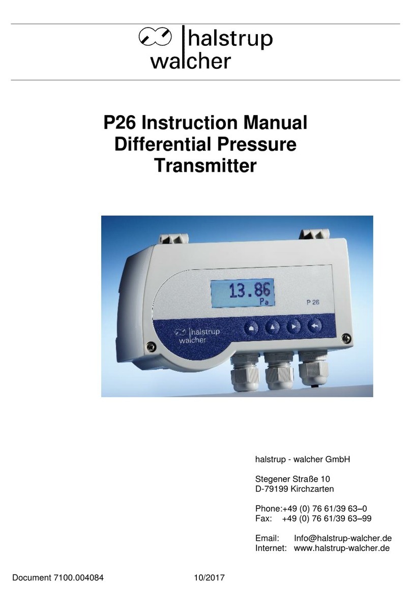
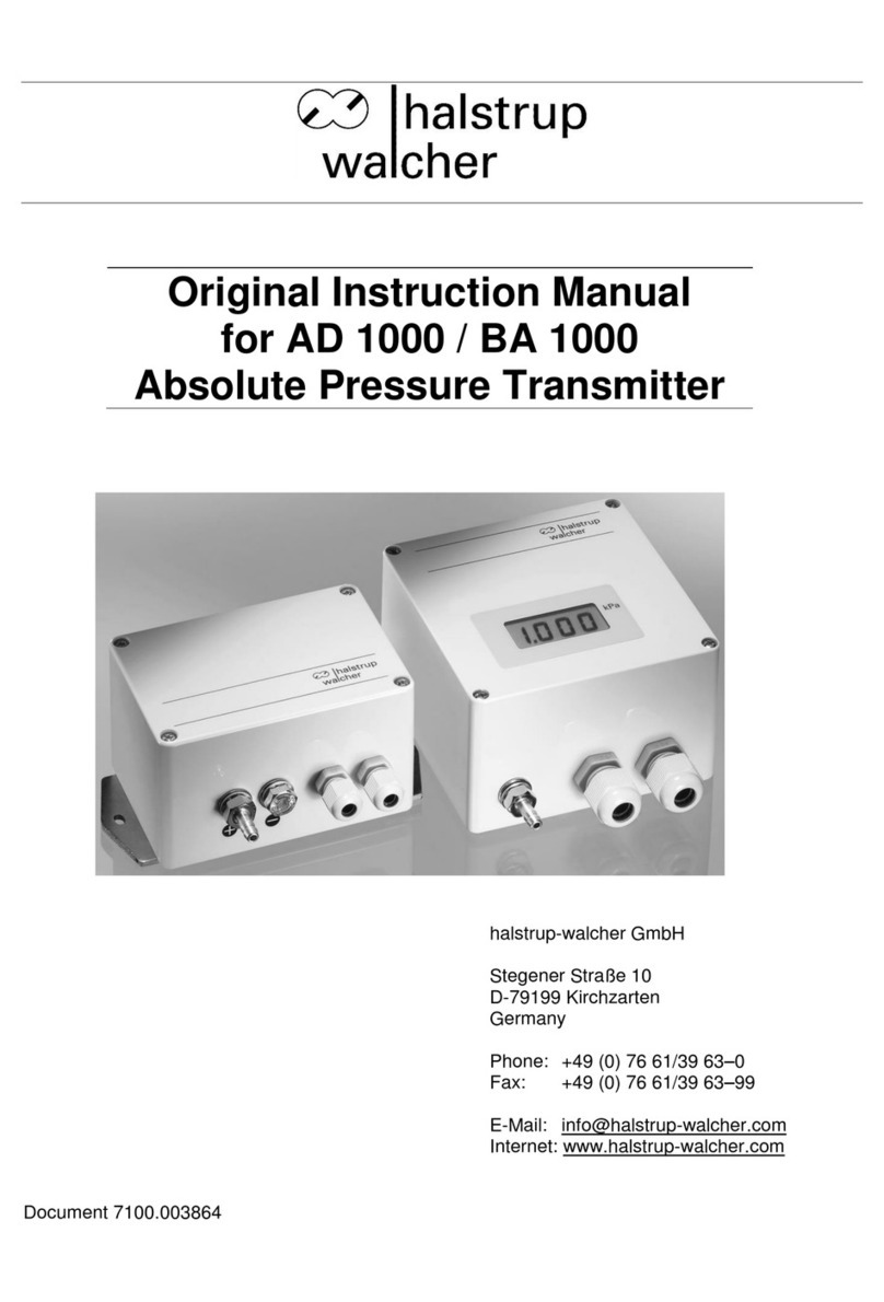
halstrup-walcher PS27 User manual

Original Operating Instructions
Differential Pressure
Transmitter PS27
halstrup-walcher GmbH
Stegener Straße 10
D-79199 Kirchzarten
Germany
Phone: +49 (0) 76 61/39 63–0
Fax: +49 (0) 76 61/39 63–99
E-mail: info@halstrup-walcher.com
Internet: www.halstrup-walcher.com
Document 7100.004354

Operating Instructions PS27
2
Revision Overview
Version:
Date:
Author:
Amendments:
A
07/2010
Sie
Initial Revision
B
07/2011
Sie
Drawings capter 3.2, 3.3 and 6
C
07/2011
Sie
Dimensional drawing
D
02/2015
Sie
Specifications
E
10/2015
Sie
Additions in capter 4 and specifications
F
03/2017
Me
Additions
G
05/2017
Me
Accuracy, Certificate of Conformity
H
05/2018
Me
better differentation between two and four-wire
I
03/2021
Me
Additions „Set Relay“
J
01/2022
Me
Revision overwiew; UKCA; M12-Plug; Certificate of Conformity
K
09/2022
RH
Measuring ranges changed
L
12/2022
Me
Update technical data, QR-Code
© 2022
The manufacturer owns the copyright to this instruction manual. It contains technical data,
instructions and drawings detailing the device’s features and how to use them. It must not be
copied either wholly or in part or made available to third parties.
The instruction manual is part of the product. Please read this manual carefully, follow our
instructions, and pay special attention to the safety information provided. This instruction
manual should be available at all times. Please contact the manufacturer if you do not
understand any part of the instructions.
The manufacturer reserves the right to continue developing this device model without
documenting such development in each individual case. The manufacturer will be happy to
determine whether this manual is up-to-date.

Operating Instructions PS27
3
Significance of the Operating Instructions
These operating instructions go into the function and handling of the
PS27 differential pressure transmitter.
Use at variance to the purpose of the transmitter and its incorrect operation may
result in risks arising for both people and assets. That is why each and every person
charged with handling the transmitter must be instructed in its use and is to be aware
of the dangers. Close attention must be given to these operating instructions and, in
particular, to the associated safety instructions. Do contact the manufacturer
should you not understand all the sections.
Be heedful of the operating instructions:
They must be readily available during the entire service life of the transmitter.
They must be passed on to the succeeding personnel charged with operations.
Any additions coming from the manufacturer must be inserted.
Conformity
This pressure transmitter conforms with the present stage reached in
technical engineering.
It complies with the statutory requirements of the EC and UK-directives.
This is documented by the CE and the UKCA mark being affixed.

Operating Instructions PS27
4
Contents
1. Safety Instructions................................................................................................5
1.1 Use for Intended Purpose Only...........................................................................5
1.2 Transport, Installation, Connection and Startup ..................................................5
1.3 Malfunctions, Maintenance, Repairs, Disposal....................................................5
1.4 Symbols..............................................................................................................6
2. Description of the pressure transmitter..............................................................6
3. Startup...................................................................................................................6
3.1 Functional Description ........................................................................................6
3.2 Connections for Four-Wire version (standard) in the device:...............................7
3.3 Connections for Two-Wire System (Option):.......................................................8
3.4 Connections M12-plug........................................................................................8
4. Resetting Offset....................................................................................................8
5. Configuring the Output Signal.............................................................................9
6. Setting the Measuring Range (Optional).............................................................9
7. Display (Option)..................................................................................................10
8. Setting the Relay Operating Point (Option).......................................................10
9. In case of Malfunctions ......................................................................................10
10. Specifications .....................................................................................................11
11. Dimensional Drawing .........................................................................................12
12. Certificates of Conformity..................................................................................13

Operating Instructions PS27
5
1. Safety Instructions
1.1 Use for Intended Purpose Only
The PS27 differential pressure transmitter registers both differential pressure and
positive/negative gauge pressure.
The operational requirements on the rating plate and in the "Specifications" chapter -
and the safe supply voltage in particular - must be kept to.
The transmitter is only to be handled in conformity with these operating instructions.
No modifications to the transmitter are permitted. The manufacturer is not liable for
damage arising from any incorrect use or one at variance to the intended purpose.
Claims to warranty in such an instance would be forfeited.
1.2 Transport, Installation, Connection and Startup
Do not block the pressure inlets on the transmitter being moved! Changes in
barometric pressure may damage transmitters with low measuring ranges.
Only qualified personnel are to assemble the appliance and see to its electrical
connections. They must be instructed as such and be assigned by the plant operator.
Only instructed persons as assigned by the plant operator are to operate the
transmitter.
Do not perform any functional test involving compressed or breathable air. This would
otherwise damage those transmitters with low measuring ranges.
Measurement errors may occur should the appliance not be protected from sunlight.
Specific safety instructions are given in the individual chapters.
1.3 Malfunctions, Maintenance, Repairs, Disposal
Malfunctions which cannot be put right as specified in Chapter 8 and damage at the
appliance itself must be immediately reported to the qualified personnel with
responsibility for the electrical connections.
The appliance must be taken out of service by the qualified personnel responsible
until the malfunction has been put right and also secured against being unintentionally
used.
Always switch off the power to the appliance before it is opened!
The appliance does not need any maintenance.
Only the manufacturer is to carry out repairs.
The electronic components of the instrument contain materials that can be reused.
That is why the appliance is to be recycled once it is finally immobilized. The
environment directives on this from the country in question must be followed.

Operating Instructions PS27
6
1.4 Symbols
The symbols below in these operating instructions point to the risks, which could arise
in handling the equipment:
WARNING!
It points to a hazard possibly extending from
injures through to death should the instructions
not be followed.
CAUTION!
It points to a hazard which could cause
considerable damage should the instructions not
be followed.
INFORMATION!
This indicates information, which is vital for
proper appliance operations
2. Description of the pressure transmitter
Type PS27 differential pressure transmitters are pneumatic/electrical sensors for
pressure testing (positive/negative gauge pressure and differential pressure)
purposes. They are typically used in air-conditioning and ventilation technology e.g.
pressure testing in ventilation ducts. The transmitter's core is a piezoresistive
pressure transmitter.
3. Startup
3.1 Functional Description
PS27 pressure transmitters are of the precision type and despite their sturdiness they
should still be treated with care. Installation right next to heat and radiation sources
e.g. radiators should be avoided as this may lead to measurement errors arising.
Ideally the appliance should be vertically mounted on a wall not subject to any
vibrations. To stop any condensed water entering the measurement cell, the
transmitter together with the hose connections for positive gauge pressure + and
negative gauge pressure - should be pointing downwards.
The right pressure sign must be used in keeping with the following table when
connecting the pressure to the transmitter:
Type of pressure
Connect pressure to
Example
pos. gauge pressure
+ input
0...1 kPa
neg. gauge pressure
- input
0...- 500 Pa
Differential pressure
Higher pressure at + input
lower pressure at - input
0...125 Pa e.g via a differential
pressure producer (e.g. measuring
orifice)
Symmetrical pressure ranges
+ input
200 Pa
Asymmetrical pressure
ranges
Input of the larger pressure
range
-300 Pa...+ 1 kPa
(here connect to + input)

Operating Instructions PS27
7
3.2 Connections for Four-Wire version (standard) in the device:
One measurement range Four measurement ranges
Note the prescribed supply voltage (see rating plate). Also follow the
connection diagram on the appliance cover / circuit board mount.
ST4 Pin
Connection name
Meaning
1
24V
Power supply input - 24VAC/DC
2
GND
Ground for power supply
3
OUT
Voltage or current output
4
GND
Ground for output signal
5
SET 0
Zero-point input (+24V zero-point is active)
The transmitter outputs are protected from short circuits. The DC-supplied appliances are
protected from reverse polarity of the supply voltage.
5 4 3 2 1
5 4 3 2 1

Operating Instructions PS27
8
3.3 Connections for Two-Wire System (Option):
One measurement range Four measurement ranges
ST4 Pin
Connection name
Meaning
1
24V
+terminal 15-32VDC
2
GND
Not used
3
OUT
-terminal
4
GND
Not used
5
SET 0
Zero-point input
3.4 Connections M12-plug
Pin
Connection name
1
24 VDC
2
Output signal
3
GND
4
GND output signal
4. Resetting Offset
After starting the pressure transmitter, give it some 15 minutes to warm up.
During this time the output signal may be unstable.
Zero-point calibration of the appliance is only effected via the input assigned for this
purpose. The user must ensure that the appliance is not subjected to any
pressure during the calibration process as this might lead to a wrong offset
value which, in turn, would result in a wrong output signal. The 24V input makes
it possible to activate a 3/2 directional control valve with the same signal, which
switches the PS27's pressure inputs at zero pressure during the zero calibration
process. In this case the zero point calibration signal must be applied until there is no
doubt that the pressure has fallen to zero.
While Resetting Offset is in progress, the power supply must not be
switched off. This might result in a loss of the device setting and may
leave the PS27 unusable.
5 4 3 2 1
5 4 3 2 1

Operating Instructions PS27
9
5. Configuring the Output Signal
The user can configure the PS27's output signal. This can be done in various ways
Output
SW Pos 3
SW Pos 4
Comments
0…10V
on
off
RLoad > 50k Ω
2…10V
on
on
RLoad > 50k Ω
0…20mA
off
off
max. load 500Ω
4…20mA
off
on
max. load 500Ω
The two-wire model must be configured by the manufacturer.
6. Setting the Measuring Range (Optional)
The transmitter with 4 measuring ranges can be adapted to the measuring
assignment in question. The teaching of 4 measuring ranges into the appliance has
been undertaken by the manufacturer. The switches 1 and 2 of SW can be used to
select the measuring range in question before the transmitter is switched on.
SW Pos 1
SW Pos 2
Measuring range
off
off
1
on
off
2
off
on
3
on
on
4
The limiting values of the measuring ranges are noted on the nameplate of the PS27.
Display-optional appliances indicate the limiting value of the selected measuring
range for 1.5 seconds after being switched-on. The appliance should be re-zeroed
following any measuring range change-over. This is because the amplification
change-over may produce offset voltages.
Four-wire: Two-wire:
Pos1 Pos2
Pos1 Pos2

Operating Instructions PS27
10
7. Display (Option)
To show up the readings, the PS27 can also be fitted out with a display. The readings
will be shown in either Pa or kPa depending on the limiting value of the measuring
range. The number of the measuring range selected is always shown on the bottom
line of the display.
On switching on a display-equipped appliance, the first thing shown is the PS27
programme version followed by a 1.5 second screening of the limiting value of the
selected measuring range and then the actual readings.
8. Setting the Relay Operating Point (Option)
The relay operating point can be adjusted with the aid of the potentiometer P2.1 (Set
Relay). Adjustment is easiest when the desired switching pressure is applied and the
potentiometer set so that the relay is just triggered.
Please note: The relay is connected to the sensor's output so that any adjusted
time delay will also cause a delay in relay triggering.
9. In case of Malfunctions
Fault description
Possible cause
Corrective action
No output signal
• Supply voltage is not
connected
• Incorrect supply voltage
connected
• Defective input protection diode
Only for DC power:
• defective reverse polarity diode
• Connect correct supply
voltage
• Connect correct supply voltage
(see rating plate)
• Send the appliance to the
manufacturer for repairs
• Send the appliance to the
manufacturer for repairs
Output signal is
constant despite
change in pressure
• Defective output protection
diode
• Pressure ports reversed
• Send the appliance to the
manufacturer for repairs
• Connect the pressure as described in
"3. Startup"
Output signal
incorrect
• Faulty pressure sensor
• Zeroing with pressure applied
For current output:
• load too high
For voltage output
• Load resistance too low
• Send the appliance to the
manufacturer for repairs
• Renewed zeroing without pressure
• Note maximum 500 load
• Note minimum 50 k load resistance
(see "10 Specifications")

Operating Instructions PS27
11
10. Specifications
Measurement accuracy: ± 2 % of the set value for ≥100 Pa
± 3 % of the set value for < 100 Pa
Temp. coefficient zero point: ± 0.1 % FS / K
Temp. coefficient span: ± 0.1 % FS / K
Measurement ranges: 50 / 100 / 200 / 500 Pa
1 / 2 / 5 / 10 kPa
As an option, the customer can use a DIP-switch to
select 4 pre-set measuring ranges
Step response time (T63): 20 ms…4s (adjustable factory provided)
(Time constant)
Pressure ports: Nominal 4 or 6 mm width for hose
Festo-Fitting 4 or 6mm
Output signals: 0/2…10 V (RL > 50 kOhm)
0/4…20 mA (RL≤ 500Ohm)
4…20 mA (two-wire 17…32 V, RL≤ 500Ohm)
Switching contact (optional): max. 230 VAC, 6 A; min. 500 mW
Display (optional): 3½-digit LCD
Overpressure limit: Range < 2 kPa : 50 kPa
Range > 10 kPa : 200 kPa
Storage temperature: -20°C...+70°C
Rated temperature range: -20°C...+60°C, with Display 0°C…50°C
Supply voltage: 24 VDC/VAC ±10 % (no galvanic isolation)
15 … 32 VDC (two-wire) (no relay output)
Power consumption: approx. 1VA
Operating position: vertical preference
Housing: see drawing
Protection class: IP 65
Installation: The appliance can be installed either on a top-hat rail
or on a wall with fastening holes
Certificates: CE / UKCA

Operating Instructions PS27
13
12. Certificates of Conformity

Operating Instructions PS27
14

Operating Instructions PS27
15
Notes:
Other manuals for PS27
1
Table of contents
Other halstrup-walcher Transmitter manuals
Popular Transmitter manuals by other brands

Avantree
Avantree BTCK-310 user manual

Jung
Jung A 41 F Series operating instructions

FlowLine
FlowLine EchoBeam LR80 Series quick start guide

FlowLine
FlowLine EchoSpan LU80 series quick start

HOLATRON SYSTEMS
HOLATRON SYSTEMS RFLS-6HSXT Operation & maintenance guide

PROCASTER
PROCASTER AMTX100 Installation and operation

Cables to Go
Cables to Go TV AVS 815 manual

Prosense
Prosense AUTOMATIONDIRECT DPTW Series Installation and maintenance instructions

HumanTechnik
HumanTechnik lisa operating instructions

Vaisala
Vaisala hmdw110 series quick guide

BFT
BFT MITTO REPLAY 2CH manual

Lightware
Lightware HDMI-3D-OPT-TX210A quick start guide